Space-Varying Cellular Neural Networks with Fuzzy Inference and RGB Component
Yasuhiro Ueda, Yoko Uwate and Yoshifumi Nishio Dept. Electrical and Electronic Eng.,
Tokushima University
Email:{ yasuhiro, uwate, nishio }@ee.tokushima-u.ac.jp
I. INTRODUCTION
Cellular Neural Networks (CNN) [1] were introduced by Chua and Yang in 1988. The idea of CNN was inspired from the architecture of the cellular automata and the neural net- works. A different point from the conventional neural networks is that CNN has local connectivity property. Since the structure of CNN resembles the structure of animals’ retina, CNN can be used for various image processing applications [2]-[6].
CNN is composed of the basic circuit units called cells. The cell contains linear and nonlinear circuit elements which are typically linear capacitors, linear resistors, linear and nonlinear controlled sources.
Wiring weights of the cells are established by parameters called the template. The performance of the CNN is decided by the template. If the templates of all the cells in the CNN are identical, the system is called space-invariant, while if the templates of all the cells in the CNN are not identical, the system is called space-varying. Typically, the space-invariant system is mainly used in the studies of the CNN because the implementation cost is low. However, the performance of the space-invariant system may be limited because the essential processing dynamics are identical for every position. On the other hand, the performance of space-varying system can be better although the design of the template and implementation are much more difficult. The research of the space-varying system is an interesting subject for developing a new direction of CNN. In particular, the design method of CNN is important problem because the design method influences on the perfor- mance of CNN.
In the previous study, we have proposed the space- varying CNN designed by Hopfield Neural Network (Hopfield NN) [7]. We prepare some existing templates and the Hop- field NN as associative memory to which some patterns are embedded. In that method, the templates of CNN was chosen according to the retrieved pattern in each cell. By using this method, we design the space-varying CNN and could perform better image processing depending on the local information of input images. We have confirmed that this system is effective for some tasks. However, we have to prepare some patterns for designing space-varying CNN. These patterns are one of the parameter of this system. Also, this method does not include the fuzziness like a human. We consider that the fuzziness like a human is necessary to design the space-varying CNN
for applying still more suitable template. In this study, we propose the space-varying CNN designed by Fuzzy inference and the RGB component of an input image. We apply some existing templates to each cell by using Fuzzy inference and the RGB component of an input image.
In 1965, L. A. Zadeh has introduced the Fuzzy set as an extension of the classical notion of set [8]. This method has performed for applying the fuzziness to computer. Fuzzy inference systems have been successfully applied in fields such as automatic control, data classification, decision analysis, expert systems and computer vision. Then, L. O. Chua et al have proposed the Fuzzy CNN [9], [10] which build the Fuzzy component into the cell. This CNN carry out the normal processing and Fuzzy processing in parallel. The performance is decided own template. They have confirmed that this CNN has characteristic performances. As the new space-varying design method, we apply one of templates to each cell ac- cording to the position of a barycenter in Fuzzy inference. In fact, we substitute Hopfield Networks for Fuzzy inference and RGB component for designing the space-varying CNN. We apply some existing templates to each cell by considering the barycenter from Fuzzy inference. To calculate the barycenter, we focus on the RGB component of an input image. We show the performance of this system by color noise removing.
In Sec. II, we describe the structure of the space-varying CNN designed by Fuzzy inference and RGB component. In Sec. III, simulation results about the color noise removing are shown. In Sec. IV, we investigate the results numerically.
Section V, concludes this article.
II. SPACE-VARYINGCELLULARNEURALNETWORKS
DESIGNED BYFUZZYINFERENCE ANDRGB COMPONENT
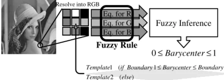
In this section, we show the design method of space-varying CNN by Fuzzy inference and the RGB component of an input image. The proposed CNN is a space-varying system which designed by RGB component in input pattern to Fuzzy inference. We describe the design method as follows. Figure 1 show the overall view.
Step 1: We resolve the color image into RGB component and calculate Eqs. (1), (2) and (3).
- 140 -
IEEE Workshop on Nonlinear Circuit Networks December 9-10, 2011
) ( 2
) 2 1
( 1
else Template
Boundary Barycenter
Boundary if
Template ≤ ≤
Fuzzy Inference
1 0≤Barycenter≤ Fuzzy Rule
Eq. for R Eq. for G Eq. for B
Resolve into RGB
Fig. 1. Design method by Fuzzy inference and RGB component of an input image.
VR in the cellC(i, j):
VR(i, j) = (
∑i+1 k=i−1
j+1∑
l=j−1
|V uR(i, j) − V u(i, j;k, l)|). (1)
VG in the cellC(i, j):
VG(i, j) = (
∑i+1 k=i−1
j+1∑
l=j−1
|V uG(i, j) − V u(i, j;k, l)|). (2)
VB in the cellC(i, j):
VB(i, j) = (
∑i+1 k=i−1
j+1∑
l=j−1
|V uB(i, j) − V u(i, j;k, l)|). (3) In Eqs. (1), (2) and (3),V u(i, j;k, l)is the gray scale value of input image. We calculate the total difference value between the center pixel and other neighborhood pixels in the pattern.
The each maximum value V is 16.0. These values are the peculiar value in each pattern.
Step 2: We prepare the membership function like Fig.2.
Fig. 2. The triangle wave function as the membership function.
In this membership function, theVR,VGorVBare assigned a value toV. We use a triangle wave function for simplifying.
The function in Fig.2 is described as follows.
µ1(y) =− Vp+ 4
4 −1
+ 1 (0≤Vp≤4), µ2(y) =−
Vp
4 −1
+ 1 (0≤Vp≤8), µ3(y) =−
Vp−4 4 −1
+ 1 (4≤Vp≤12), µ4(y) =−
Vp−8 4 −1
+ 1 (8≤Vp≤16),
µ5(y) =−
Vp−12 4 −1
+ 1 (12≤Vp≤16). (4) We substitute the value of Eqs. (1), (2) and (3) into this membership function and calculate eachµ(y)of each triangle wave function. The µ(y)is the degree for the inference.
Step 3: Forth, we choose “Logic AND” operation or “Logic OR” operation. Fuzzy inference is composed by the hypothesis and the consequent. In the hypothesis, we can choose “Logic AND” operation or “Logic OR” operation. By using three kinds ofV p, we obtain three kinds ofµ(y), respectively. Also we can choose one of the µ(y) by using this operation. We describe an example about it by V pR= 4.5,V pG= 6.0and V pB= 1.0 as follows.
Fig. 3. Sample for “Logic AND” operation or “Logic OR” operation.
In Fig.3,µ(y)ofV pRis0.875, that ofV pGis0.5and that ofV pBis0.25. If we choose the “Logic AND” operation, the µ(y) is set into 0.875. On the other hand, if we choose the
“Logic OR” operation, the µ(y)is set into 0.25.
Step 4:
0 0.2 0.4 0.6 0.8 1 1.2
0 0.2 0.4 0.6 0.8 1 1.2
μ(y)μ(y)μ(y)μ(y)
yyyy
μ1´(y) μ2´(y) μ3´(y) μ4´(y) μ5´(y)
Fig. 4. Singleton for the consequent.
We substitute the hypothesis value into Fig. 4for calculate the consequent. Figure4 is the graph for the consequent. For simplifying, we apply the simplified-inference method. In this method, we use the singleton which having only the hight. We substitute eachµ(y)of the hypothesis into the hight by Fig.4.
Step 5: We calculate the barycenter by Eq. (5) form the value of all the consequent.
y0 =
∫y·µ′(y)
∫ µ′(y) . (5) In Eq. (5), y0 is the barycenter. µ′(y) is each value of triangles calculated by Eqs. (1), (2), (3) and Fig. 2. Also, y is each value on xaxis in Fig. 4. In this study, the value of the barycenter is form0 to1.0. By these ways, we obtain the barycenter of input patterns.
- 141 -
Step 6: We apply each template to each cell by using each barycenter. We set up the two parameters asBoundary1 andBoundary2 for applying template. The state equation is updated as follows.
State equation by Template 1:
dvxij
dt = −vxij+
∑i+r k=i−r
∑j+r l=j−r
A1(i,j;k,l)vykl(t)
+
∑i+r k=i−r
∑j+r l=j−r
B1(i,j;k,l)vukl(t) +I1, (Boundary1 ≤y0≤Boundary2). (6) State equation by Template 2:
dvxij
dt = −vxij+
∑i+r k=i−r
j+r∑
l=j−r
A2(i,j;k,l)vykl(t)
+
∑i+r k=i−r
∑j+r l=j−r
B2(i,j;k,l)vukl(t) +I2, (otherwise). (7) Hence, the input image is processed by using each applied template in the space-varying CNN designed by Fuzzy infer- ence.
III. SIMULATIONRESULTS
In this paper, we show the simulation results about color noise removing with “Pepper” image. The input images in- clude red, blue, green and black noise, respectively. In this simulation, we choose “Heat Diffusion” template and “Keep Value” template as follows.
“Heat Diffusion” template:
A=
0.1 0.15 0.1 0.15 0 0.15
0.1 0.15 0.1
, B= 0, I = 0. (8)
“Keep Value” template:
A=
0 0 0 0 1 0 0 0 0
, B= 0, I= 0. (9)
Figure 5shows the reason why we choose “Heat Diffusion”
template and “Keep Value” template and the mechanism how to remove noise. In this figure, “HD” means the cell corre- sponding to the “HD” is applied “Heat Diffusion” template.
Also, “KV” means the cell which corresponding to the “KV”
is applied “Keep Value” template. Usually, the “Heat Diffu- sion” template make all pixels 0 like Fig.5. In our proposed system, the “Heat Diffusion” template is applied on the noise and the “Keep Value” template applied on the other pixels.
On the noise pixels, the “Heat Diffusion” template obtains the neighbor value and makes itself the average value. Also, the neighbor pixels keep itself by “Keep Value” template.
KV KV KV
KV HD KV
KV KV KV
HD HD HD
HD HD HD
HD HD HD
Fig. 5. The mechanism of removing the noise.
Therefore, the center pixel which is applied “Heat Diffusion”
template becomes the average in3×3pixels. As a result, the noises are diffused and removed. The simulation results are shown as follows.
(a) (b) (c) (d)
(e) (f) (g) (h)
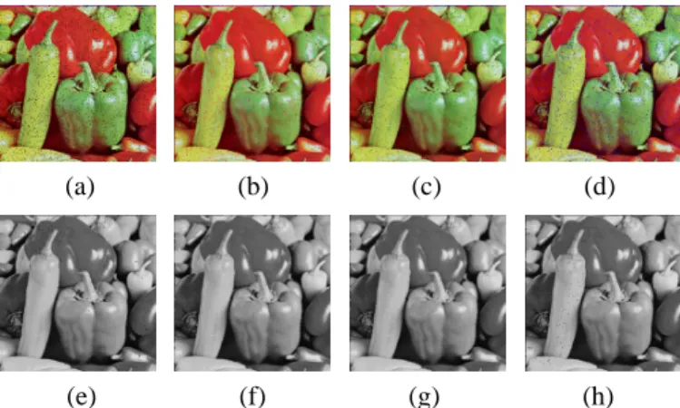
Fig. 6. “Pepper” images as input image and output images. (a) “Pepper”
image include black noise. (b) “Pepper” image include red noise. (c) “Pep- per” image include green noise. (d) “Pepper” image include blue noise.
(e) Black noise removed result (Boundary1 = 0.1,Boundary2 = 0.33 and “Logic OR” processing in Fuzzy component). (f) Red noise removed result (Boundary1= 0.1,Boundary2= 0.35and “Logic OR” processing in Fuzzy component). (g) Green noise removed result (Boundary1 = 0.1, Boundary2 = 0.33and “Logic AND” processing in Fuzzy component).
(h) Blue noise removed result (Boundary1= 0.1,Boundary2= 0.36and
“Logic AND” processing in Fuzzy component).
Figures 6(a), (b), (c) and (d) show the input images in- cluding color noises. Figures 6(e), (f), (g) and (h) show the simulation results. The other parameter is shown in the caption of each image. In the output images, almost noises are removed. On the noise pixels, the cell is applied the “Heat Diffusion” template. On other pixels, the cell is applied the
“Keep Value” template. These templates are applied by Fuzzy inference effectively. However, the part of the edge is little diffused by “Heat Diffusion” template because of the false applying.
IV. RESULTVERIFICATION ABOUTNOISEREMOVING
In this section, we investigate the results numerically. To calculate the error for noise removing, we use following equations.
- 142 -
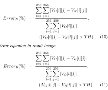
Error equation in noise image:
ErrorN(%) =
∑256 i=1
∑256 j=1
|VO[i][j]−VN[i][j]|
∑256 i=1
∑256 j=1
|VO[i][j]| ,
(|VO[i][j]−VN[i][j]|> T H). (10) Error equation in result image:
ErrorR(%) =
∑256 i=1
∑256 j=1
|VO[i][j]−VR[i][j]|
∑256 i=1
∑256 j=1
|VO[i][j]| ,
(|VO[i][j]−VR[i][j]|> T H). (11) In Eqs. (10) and (11),VO[i][j] is the original value in the cell C(i, j). Also VN[i][j] is the noised value and VR[i][j]
is the result value in the cell C(i, j). The “T H” is the threshold value. We calculate the error between the original image and its noise image or the output image by these equations. The smaller error describes that the noise image or the output image is similar to the original image. In fact, this is the characteristic that the proposed system can remove noise effectively. Additionally, we add the difference upward of the set threshold value. We change the threshold value“T H”and investigate the transition of error. When the “T H” is 0, we calculate the error at all pixels.
0 2 4 6 8 10 12
0 0.2 0.4 0.6 0.8 1 NOISE RESULTS
Threshold
Error(%)
0 2 4 6 8 10 12
0 0.2 0.4 0.6 0.8 1 NOISE RESULTS
Threshold
Error(%)
(a) (b)
0 2 4 6 8 10 12
0 0.2 0.4 0.6 0.8 1 NOISE RESULTS
Threshold
Error(%)
0 2 4 6 8 10 12
0 0.2 0.4 0.6 0.8 1 NOISE RESULTS
Threshold
Error(%)
(c) (d)
Fig. 7. The transition of error by changing the Threshold valueT H. (a) A black noise image and its result. (b) A red noise image and its result. (c) A green noise image and its result. (d) A blue noise image and its result.
In Fig. 7, the transition of the error between the original image and the noise image is small when we change the
“T H”. On the other hand, the transition of the error between the original image and the output image change rapidly around that the“T H”is set to0.1. In Fig.6, the noise removing has been carried out enough visually. Therefore, we consider that
human is not care about the difference if the output image is similar to the original image totally. Thus, the error decrease rapidly around that the “T H” is set to 0.1 by removing the little difference.
V. CONCLUSIONS
In this study, we have proposed the space-varying CNN designed by Fuzzy inference and the RGB component of an input image and investigate it. This method needs only three parameters for designing and some existing templates for processing. We have shown the performance of this system by color noise removing. From some simulation results, we have succeed to remove almost color noises from a general image.
The performance of this system depends on the parameters.
In the future work, we would like to propose the automatic system to decide these parameters. Also under−0.1, the error of result image is larger than that of noise image. We have considered that human correct the little difference.
REFERENCES
[1] L.O. Chua and L. Yang, “Cellular Neural Networks:Theory,” IEEE Trans.
Circuits Syst., vol. 32, pp. 1257-1272, Oct. 1988.
[2] F. Dirk and T. Ronald, “Coding of Binary Image Data using Cellular Neural Networks and Iterative Annealing,” Proc. of ECCTD’03, vol. 1, pp. 229-232, Sep. 2003.
[3] M. Namba and Z. Zhang, “Cellular Neural Network for Associative Memory and its Application to Braille Image Recognition,” Proc. of IJCNN’06, pp. 4716-4721, Jul. 2006.
[4] H. Koeppl and L.O. Chua, “An Adaptive Cellular Nonlinear Network and its Application,” Proc. of NOLTA’07, pp. 15-18, Sep. 2007.
[5] T. Kozek, K.R. Crounse, T. Roska and L.O. Chua, “Smart Image Scanning Algorithms for the CNN Universal Machine,” Proc. of NOLTA’95, vol. 2, pp. 707-712, 1995.
[6] K. Sumitomo and A. Ushida, “A Design Method of Cellular Neural Networks Using Fuzzy Inference,” IEICE Technical Report, no. NLP98- 443, pp. 39-46, Dec. 1998.
[7] Y. Ueda, M. Kawahara, T. Inoue, Y. Uwate and Y. Nishio, ”Space-Varying Cellular Neural Networks Designed by Hopfield Neural Network,” Proc.
of IJCNN’10, pp. 3770-3775, Jul. 2010.
[8] L. A. Zadeh, “Fuzzy Sets as a Basis for a Theory of Possibility,” Fuzzy Sets Syst., Vol. 1, Issue 1, pp. 3-28, Jan. 1978.
[9] T. Yang and L.B. Yang, “Fuzzy cellular neural network: theory,” Proc.
Int. Workshop on Cellular Neural Networks and Their Applications (CNNA’96), pp. 181-186, 1996.
[10] T. Yang and L.B. Yang, “Fuzzy cellular neural network: applications,”
Proc. Int. Workshop on Cellular Neural Networks and Their Applications (CNNA’96), pp. 225-230, 1996.
[11] Cellular Sensory Wave Computers Laboratory Computer and Automa- tion Research Institute Hungarian Academy of Sciences, “Cellular Wave Computing Library (Template, Algorithms, and Programs) Version 2.1”.