Possibility of Image Processing by CNN Using Two Kinds of Cloning Templates
Yoshio Nakayama Dept. Media and Information Syst.,
Shikoku University Email:[email protected]
Yasuteru Hosokawa Dept. Media and Information Syst.,
Shikoku University
Email:[email protected]
Yoshifumi Nishio
Dept. Electrical and Electronic Eng., Tokushima University
Email:[email protected]
Abstract—Many modified CNN have been proposed. However, most of modified CNN are lost the simplicity of the system.
In this study, new cloning template of CNN using two kind of cloning templates is proposed. By some computer simulations, possibility of image processing by CNN using two kinds of cloning templates is revealed.
I. INTRODUCTION
Cellular Neural Networks (CNN) proposed by Chua and Yang [1][2] can be carried out many kinds of image process- ing. The characteristic of CNN depend on a cloning template.
A combination of processing using some cloning templates has ability of enable processing that conventional systems are not done. However, an ability of one processing is limited.
Thus, many modified CNN have been proposed.
Most of modified CNN obtained higher ability, lost the sim- plicity of the system. The simplicity is important for integrated circuit implementation of CNN. As one of modified systems which is not lost the simplicity, cellular neural network using two kinds of cloning templates was proposed by Fujii et al[6].
The system was investigated as coupled oscillatory system mainly. Active pattern formations, clustering and so on are observed. On the other hand, application of the systems is not investigated.
In this study, new cloning template of CNN using two kind of cloning templates is proposed. By some computer simulations, possibility of image processing by CNN using two kinds of cloning templates is revealed.
II. CNNUSING TWO KIND OF CLONING TEMPLATES
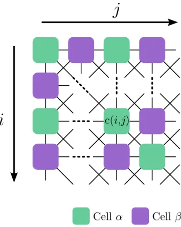
Figure 1 shows a structure of CNN using two kind of cloning templates. Cell α and Cell β have different cloning templates. Two kinds of cells are placed as a checkered.
The state equations are shown as follows, 1: Cellα(i+j is even number)
dxij
dt =−xij+Iα
+ ∑
c(k,l)
Aα(i, j;k, l)ykl
+ ∑
c(k,l)
Bα(i, j;k, l)ukl
(1)
j
i c(i,j)
Cell α Cell β
Fig. 1. Structure of Two Template CNN.
2: Cellβ (i+j is odd number) dxij
dt =−xij+Iβ
+ ∑
c(k,l)
Aβ(i, j;k, l)ykl
+ ∑
c(k,l)
Bβ(i, j;k, l)ukl
(2)
A{αβ}(i, j;k, l)ykl,B{αβ}(i, j;k, l)ukl,I{αβ}show feedback value, input value, bias value, respectively. The output function is shown as follows.
yij =f(xij). (3)
- 81 -
IEEE Workshop on Nonlinear Circuit Networks December 13-14, 2013
Fig. 2. Computer Simulation Result.
where
f(x) = 0.5(|x+ 1| − |x−1|). (4) The boundary is set as fixed boundary condition. The value is set as 1.
III. IMAGE PROCESSING BYCNNUSING TWO CLONING TEMPLATES
A. Proposed Cloning Templates
Proposed cloning template is shown as follows.
Aα=
2 0 2 0 2 0 2 0 2
, Aβ=
2 1 2 1 2 1 2 1 2
Bα=
0 1 0 1 0 1 0 1 0
, Bβ =
−1 −1 −1
−1 2 −1
−1 −1 −1
, Iα= 2, Iβ=−2.
(5)
This cloning template is based upon hole filling and noise de One of the computer simulation result is shown Fig.2. Figure2 (a) shows the original image. Figure 2 (b) shows the result.
Dark area becomes black and bright area becomes white. Gray area becomes checkered pattern. It means that intermediate area of brightness can be extract in one processing. This template can adjust the intermediate area by changing I, However, details of the original image is disappeared. In order to reveal the characteristics of CNN using two kinds of cloning templates, computer simulations are carried out about some images.
B. the case that image width is even number
In this system, the result is influenced by height or width of an image. For instance, when image width is even number, left upper cell and right upper cell become different cell types (Cell α and Cell β.) On the other hand, when image width is odd number, left upper cell and right upper cell become same types (Cellαor Cellβ.) In this subsection, the case that image width is even number is shown.
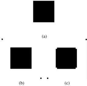
Figure 3 shows a computer simulation result. Figure 3 (a) shows a original image which is drawn square, (b) shows in case that left upper cell is cell α, (c) shows in case that
(a)
(b) (c)
Fig. 3. Computer Simulation Result (square.) (a) Original image, (b) Case of left upper cell is cellα, (c) Case of left upper cell is cellβ.
left upper cell is cell β. Namely, a difference of two cases is positions of cell alpha and cell beta. In all simulation results, (a), (b) and (c) show same meaning, respectively. In Figure 3 (b), black dots are observed in a left upper cell and a right lower cell. Excepting two dots, this result is same as the original image. In Figure3(c), black dots are observed in a right upper cell and a left lower cell. Additionally, corner dots of the square become white.
In the case of Fig 4, black dots appear two corners of the image. A edge of the circle changes a little.
In the case of Fig 5, black dots appear corners of the image. Additionally, a edge of the hypotenuse of a right triangle is expand in the case of Fig. 5 (b). The reason is the boundary condition which is set as black. On right top and left bottom side, some pixels are surrounded by black pixels.
Therefore, these pixels become black. Then these changes propagate to center along the edge of the hypotenuse. Finally, the hypotenuse is expand.
In the case of Fig 6, lower, middle and upper area become black, checkered and white, respectively. The result shows that the image is divided into three areas by brightness. White area is surrounded by black dots because boundary condition is black. Figure6(b) is same as inverted Fig.6 (c) horizontally.
The difference is that checkered dots are inverted.
C. the case that image width is odd number
In this subsection, image size is set as 33 ×33. Namely, two corner of top of images is set as Cell α and Cell α or Cell β and Cellβ.
Figure7 shows a computer simulation result in the case of a square. Figure 7 (a) shows a original image. Figure 7 (b) and (c) show in case that four corners are set as cellαor cell β, respectively. In Figure 7 (b), four dots observed on four corners and the square is not change. In Figure 7 (c), four
- 82 -
(a)
(b) (c)
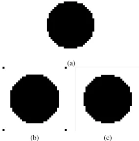
Fig. 4. Computer Simulation Result (circle.) (a) Original image, (b) Case of left upper cell is cellα, (c) Case of left upper cell is cellβ.
(a)
(b) (c)
Fig. 5. Computer Simulation Result (triangle.) (a) Original image, (b) Case of left upper cell is cellα, (c) Case of left upper cell is cellβ.
dots did not observe on four corners and corners of the square is lacked.
Figure8shows a computer simulation result in the case of a circle. Figure 8 (a) shows a original image. Figure 8 (b) and (c) show in case that four corners are set as cell α or cell β, respectively. In Figure 8 (b), four dots observed on four corners appear and the circle is changed some pixels on edges. In Figure8 (c), there is no changes.
Figure9shows a computer simulation result in the case of a triangle. Figure9 (a) shows a original image. Figure 9 (b) and (c) show in case that four corners are set as cellαor cell β, respectively. In Figure9(b), three dots observed on corners appear and the triangle is no changes. In Figure9(c), a edge of the hypotenuse is expand and right top and left bottom areas
(a)
(b) (c)
Fig. 6. Computer Simulation Result (gradation.) (a) Original image, (b) Case of left upper cell is cellα, (c) Case of left upper cell is cellβ
(a)
(b) (c)
Fig. 7. Computer Simulation Result. (a) Original image, (b) Case of four corners are cellα, (c) Case of four corners are cellβ
become black.
Figure9 shows a computer simulation result in the case of a gradation. Figure 9(a) shows a original image. Figure9 (b) and (c) show in case that four corners are set as cellαor cell β, respectively. Figure 10 (b) and (c) are symmetric in the center line.
D. Consideration
In the case of even numbers, images become asymmetry.
It is not suitable for image processing. In the case of odd numbers, two results are obtained by depending on cell ar- rangement. The boundary condition is set as black. Therefore, dots of corners appeared. It is not important. However, an object which have a slant changes by depending on cell
- 83 -
(a)
(b) (c)
Fig. 8. Computer Simulation Result. (a) Original image, (b) Case of four corners are cellα, (c) Case of four corners are cellβ
(a)
(b) (c)
Fig. 9. Computer Simulation Result. (a) Original image, (b) Case of four corners are cellα, (c) Case of four corners are cellβ
arrangement. By paying attention to this point, we can obtain the image divided into three areas by brightness.
IV. CONCLUSIONS
In this study, new cloning template of CNN using two kinds of cloning templates has been proposed. By some computer simulation results, following characteristics are shown. This template is suitable for images which have odd number width and height. In CNN using two kinds of cloning templates, cell arrangement is influence to the result of image processing.
This template can be obtained the image divided into three areas by brightness.
(a)
(b) (c)
Fig. 10. Computer Simulation Result. (a) Original image, (b) Case of four corners are cellα, (c) Case of four corners are cellβ
REFERENCES
[1] L. O. Chua and L. Yang, “Cellular Neural Networks: Theory,” IEEE Trans. Circuits Syst., vol. 35, no. 10, pp. 1257–1272, 1988.
[2] L. O. Chua and L. Yang, “Cellular Neural Networks: Applications,”IEEE Trans. Circuits Syst., vol. 35, no. 10, pp. 1273–1290, 1988.
[3] L. O. Chua, M. Hasler, G. S. Moschytz and J. Neirynck, “Autonomous Cellular Neural Networks: a unified paradigm for pattern formation and active wave propagation,”IEEE Trans. Circuits Syst. I, vol. 42, no. 10, pp. 559–577, 1995.
[4] P. Arena, S. Baglio, L. Fortuna and G. Manganaro, “Self-Organization in a Two-Layer CNN,”IEEE Trans. Circuits Syst. I, vol. 45, no. 2, pp. 157–
162, 1998.
[5] Z. Yang, Y. Nishio and A. Ushida, “Generation of Various Types of Spatio-Temporal Phenomena in Two-Layer Cellular Neural Networks,”
IEICE Trans. Funds., vol. E87-A, no. 4, pp. 864–871, 2004.
[6] J. Fujii, Y. Hosokawa and Y. Nishio, “Wave Phenomena in Cellular Neural Networks Using Two Kinds of Template Sets,” Proc. of NOLTA’07, pp. 23–26, 2007.
[7] M. Oda, Z. Yang, Y. Nishio and A. Ushida,k “Analysis of Two- Dimensional Conductive Plates Based on CNNs,” Proc. of NCSP’05, pp. 447–450, 2005.
[8] Z. Yang, Y. Nishio and A. Ushida, “Image Processing of Two-Layer CNNs — Applications and their Stability,”IEICE Trans. Funds., vol. E85- A, no. 9, pp. 473–490, 2002.
[9] Z. Yang, K. Tsuruta, Y. Nishio and A. Ushida, “Investigation of Phase- Wave Propagation Phenomena in Second Order CNN Arrays,”Proc. of ISCAS’04, vol. 3, pp. 49–52, 2004.
- 84 -