Investigation of Switching Phenomena in Coupled Chaotic Circuits as a Ring Structure
Takuya Nishimoto Dept. Information Business,
Shikoku University
Email:[email protected]
Yasuteru Hosokawa
Dept. Media and Information System, Shikoku University
Email:[email protected]
Yoshifumi Nishio
Dept. Electrical and Electronic Eng., Tokushima University Email:[email protected]
Abstract— Switching phenomena of attractors can be observed in double scroll chaotic circuits. In our previous study, a synchro- nization of switching phenomena in a full-coupled chaotic circuits have been confirmed. It is very interested that the phenomenon can be observed in an asynchronization state.
In this study, we investigate a coupled chaotic circuits as a ring structure. By carrying out some computer simulations, a mechanism of the phenomenon are revealed.
I. INTRODUCTION
Synchronization can be observed in everywhere. For in- stance, there are synchronization of two pendulum clock reported by Huygens, a relationship between rotation period of the Earth and revolution period of moon, firefly synchro- nization and so on. Therefore, investigating synchronization of coupled oscillatory systems is very important.
In coupled chaotic circuits, synchronization is also ob- served. Since this phenomenon reported by Pecora et al. [1], many researchers of coupled chaotic circuits pay attention to synchronization.
On the other hand, some chaotic circuits have double scroll attractors. In these circuits, switching phenomena of attractors are observed by changing parameters. Self-switching phenom- ena in coupled double scroll circuits reported by Sekiya et al.
[2]. In this case, these circuits are not synchronized. Therefore, we can say that this phenomenon includes synchronization and asynchronization. We consider that this is very interesting phenomenon.
In our previous study [3], we have observed similar phe- nomenon in another circuit and another coupling topology. The phenomenon is also asynchronization state and anti-phase syn- chronization of switching of attractors are observed. However, we could not explain the mechanism of this phenomenon.
In this study, we investigate the case of same chaotic circuit and another coupling topology. This investigation reveals the mechanism.
II. SYNCHRONIZATION OFSWITCHINGPHENOMENA
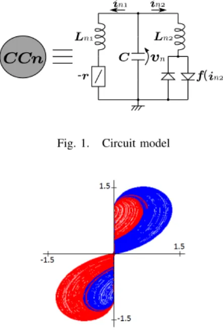
A circuit model [4] using in this study is shown in Fig.1.
Figure 2 shows its computer simulation result. Double scroll attractors are observed and two attractors are symmetrical about a origin. In this result, attractors are color-coded by following rules. In the case ofy ≥0.675,z = 1 andy <˙ 0, the color is set as blue. The other case, namely, the case of
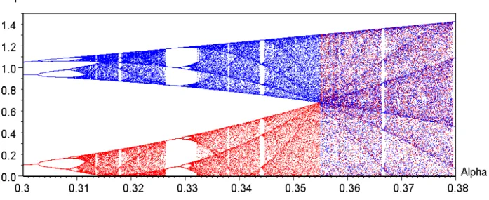
y < 0.675, z = 1 and y <˙ 0, the color is set as red. We define the Poincar´e section z = 1 and y <˙ 0. Colors are distinguished by y = 0.675. This distinction is derived from a bifurcation diagram as shown in Figure 3 that is used two kinds of initial values. In this paper, this definition is applied in all of the simulations. Double scroll attractors are observed inα >0.356.
In our previous study, chaotic circuits coupled by resistors as shown in Fig. 4 was investigated. The system equation is described as follows:
L1
din1
dt = vn+rin1, L2
din2
dt = vn−rd
2
in2+ V rd
− in2− V
rd
, Cdvn
dt = −(in1+in2)−G N vn− XN k=1
vk
! .
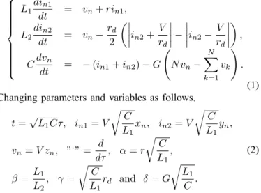
(1) Changing parameters and variables as follows,
t=√
L1Cτ, in1=V rC
L1xn, in2=V rC
L1yn, vn =V zn, ”·” = d
dτ, α=r rC
L1
, β =L1
L2
, γ= rC
L1
rd and δ=G rL1
C.
(2)
The normalized system equation is described as follows.
˙
xn =zn+αxn,
˙ yn=β
zn−γ
2
yn+1 γ
− yn−1
γ
,
˙
zn=−xn−yn−δ N zn− XN k=1
zk
! (3)
where N is corresponding the number of the circuits and n is corresponding the circuit number. Figure 5 shows one of its computer simulation results. Horizontal axes are time and vertical axes are z1, z2, z3 and z4 which are corresponding to voltages of each circuit. Switching phenomena of attractors are observed at the same time. However, all waves are not synchronized each other. Additionaly, there are no parameter errors. We call this phenomenon synchronization of switching phenomena.
- 112 -
IEEE Workshop on Nonlinear Circuit Networks December 9-10, 2011
L C
-r f( )
n1 Ln2
in2 in2
in1
vn n
CC
Fig. 1. Circuit model
Fig. 2. Computer simulation result of a chaotic circuit as shown in Fig.1.
α= 0.40andβ= 3.0
Normally, in the case of a synchronization state, the switch- ing of attractors is also synchronized. And in the case of asynchronous states, the switching of attractors is also asyn- chronized. Therefore, we consider that the phenomena is very interesting phenomena. This phenomenon is reported by [2].
Differences between [2] and our study are follows.
In our system,
• There are no parameter errors.
• Two kinds of attractors are observed at the same time.
• Circuit topology is full-coupled.
In this study, we investigate switching phenomena in cou- pled chaotic circuits as a ring structure and reveal the mech- anism of this phenomenon.
III. COUPLEDCHAOTICCIRCUIT WITH ARING
STRUCTURE
We investigate coupled chaotic circuits which is coupled by resistors shown in Fig. 6. The circuit topology is a ring structure.
Firstly, a system equation is derived. Bi-directionally- coupled diodes are modeled as Fig.7. This model is described as following function
vd= 2V u(id)−V, (4) whereV is a threashold voltage of a diode andu()is a step function. The other elements are modeled as linear elements.
Each circuit number is defined as1≤n≤N. By using these
Fig. 4. System model in our previous study.N= 4.
Fig. 5. Computer simulation result of coupled chaotic circuits as shown in Fig.4. Horizontal axes are time and vertical axes arez1,z2,z3 andz4
which are corresponding to voltages of each circuits.α= 0.405,β= 3.0 andδ= 0.20.
models, system equation is described as follows:
L1
din1
dt = vn+rnin1, L2n
din2
dt = vn−(2V u(id)−V), Cdvn
dt = −(in1+in2)−G(2vn−vn−1−vn+1). (5) Changing parameters and variables as follows,
t=√
Ln1Cτ, in1=V r C
Ln1
xn, in2=yn, vn=V zn, ”·” = d
dτ, α=r rC
L1
, β =
√Ln1C
L2n and δ=G rLn1
C .
(6)
The normalized system equation is described as follows.
˙
xn = αxn+zn
˙
yn = β{zn−(2u(yn)−1)}
˙
zn = −xn−yn
−δ(2zn−zn−1−zn+1) (n= 1,2,· · ·, N)
(7)
where
z0=zN, zN+1=z1. (8) IV. COMPUTERSIMULATIONS
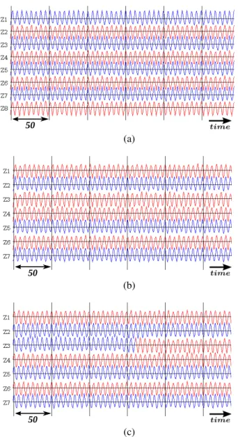
Figure 8 shows simulation results of the system as shown in Fig. 6. Horizontal axes show time and vertical axes show voltages of each circuit. In this system, synchronization of switching phenomena is not observed except for the case of
- 113 -
Fig. 3. One parameter bifurcation diagram of result of a chaotic circuit as shown in Fig.1.β= 3.0. Initial values arex=−0.1,y=−0.1,z=−0.1 andx= 0.1,y= 0.1,z= 0.1.
the number of circuit is 3. A ring and full-coupled topology is same that in the case of N = 3. Figure 10 shows the phenomena in the case of the number of circuit is 3. In the case ofN >3, when the number of circuits is even numbers, two attractors are observed alternately like Fig. 8 (a). When the number of circuits is odd numbers, basically, two attractors are observed alternately. However, there is a point where neighboring attractors become a same type attractor. This point keeps moving as shown in Figs.8 (b) and8(c). These results show that the neighboring circuit becomes a different attractor in spite of coupled by resistors. We consider that the reason as follows.
Figure 9 shows a simulation result in the case that the number of circuit is two. Horizontal axes are time. Vertical axes are z1, z2, y1 and y2 which are corresponding to v1, v2,i12, i22, respectively. Normally, in-phase synchronization is observed in a system coupled by resistors. In this case, waveforms are similar each other. A current flows a coupling resistor in order to decrease a voltage difference between two circuits. Therefore, directions of two currents i12 andi22 are reverse each other. This flow makes directions of threshold voltages of bi-directionally-coupled diodes reverse each other.
This is the reason why these are not synchronized.
V. CONCLUSIONS
In this study, switching phenomena in coupled chaotic circuits as a ring structure is investigated. As a result, a mechanism of synchronization of switching phenomena in coupled chaotic circuits are revealed.
REFERENCES
[1] L. M . Pecora and T. L. Carroll, “Synchronization in Chaotic Systems,”
Phys. Rev. Lett., vol. 64, pp. 821–824, 1990.
[2] H. Sekiya, S. Mori and I. Sasase, “Synchronization of Self-Switching Phenomena on Full-Coupled Chaotic Oscillators,”IEICE Trans., vol. J83- A, no. 11, pp. 1264–1275, 2000.
CC1
3 2
n
N
Fig. 6. System model in this study.
f( ) i
di
dV
-V
i f( )
d
i
d(a) Circuit schematic. (b)i-v characteristics.
Fig. 7. Bi-directionally-coupled diodes model.
[3] T. Nishimoto, Y. Hosokawa and Y.Nishio, “Anti-phase Synchronization of Switching Phenomena in Globally Coupled System of Chaotic Circuits,”
IEICE Technical Report, pp. 1–4, 2010.
[4] Y. Nishio, N. Inaba, S. Mori and T. Saito, “Rigorous Analyses of Windows in a Symmetric Circuit,”IEEE Trans. Circuit and Systems., vol. 37, no. 4, pp. 473–487, 1990.
[5] T. Yamada, Y. Hosokawa and Y. Nishio, “Quasi Synchronization Phenom- ena in Coupled Chaotic Systems as a Ladder,”Proc. of IEEE International Workshop on Nonlinear Circuit Networks, pp. 68-71, 2008.
- 114 -
50
(a)
50
(b)
50
(c)
Fig. 8. Computer simulation results of the system model as shown in Fig.6.
α= 0.405,β = 3.0andδ= 0.20. (a)N = 8. (b)N = 7. (c)N = 7.
Differential initial values are applied in (b) and (c).
50
Fig. 9. Computer simulation results of the system model as shown in Fig.6.
N= 2.α= 0.405,β= 3.0andδ= 0.20.
250
Fig. 10. Computer simulation results of the system model as shown in Fig.6.N= 2.α= 0.405,β= 3.0andδ= 0.21.
- 115 -