Double-Mode Simultaneous Oscillation in Coupled Hard Oscillators
Saori Fujioka, Yoko Uwate and Yoshifumi Nishio Dept. Electrical and Electronic Eng.,
Tokushima University
2-1 Minami-Josanjima,Tokushima,Japan Email: [email protected]
Abstract—In this study, synchronization phenomenon observed
from two inductively coupled simultaneous oscillators can exhibit both in-phase and anti-phase synchronizations. We can confirm the phenomenon that double-mode and simultaneous oscillation is generated at the same time.
I. I ntroduction
In 1954, Scha ff ner reported that an oscillator with two degrees of freedom could oscillate simultaneously at two di ff erent frequencies when the nonlinear characteristics are described by a fifth-power polynomial function [1]. Kuramitsu investigated the simultaneous oscillations for three or more degrees case theoretically and confirmed the generation of triple mode oscillation by circuit experiments [2]. Simulta- neous oscillations are definitely one of the most common nonlinear phenomena observed in various higher-dimensional systems in the natural fields. However, after their pioneering works, as far as the authors know, there have not been many researches clarifying the basic mechanism of the simultaneous oscillations except [3][4].
In our past study, we have reported synchronization phe- nomena observed from two resistively coupled simultaneous oscillators [5] and two inductively coupled simultaneous os- cillators [6]. In this study, we investigate two inductively cou- pled simultaneous oscillators with more degrees of freedom.
We confirm the generation of various interesting modes of oscillations from the circuits.
II. C ircuit model
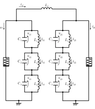
The circuit model is shown in Fig. 1. In the circuit, two simultaneous oscillators with three LC resonators are coupled by an inductor L
Cand each simultaneous oscillator consists of a nonlinear negative resistor, whose v − i characteristics are described by a fifth-power polynomial function as
i
R(v) = g
1v − g
3v
3+ g
5v
5(g
1, g
3, g
5> 0) (1) and three resonators with di ff erent natural frequencies. The equations governing the coupled oscillators are described by the following 12th-order di ff erential equations including two
nonlinear functions i
R1and i
R2.
C
1dv
11dt = − i
11− i
R1− i
C, L
1di
11dt = v
11C
2dv
12dt = − i
12− i
R1− i
C, L
2di
12dt = v
12C
3dv
13dt = − i
13− i
R1− i
C, L
3di
13dt = v
13C
1dv
21dt = − i
21− i
R2+ i
C, L
1di
21dt = v
21C
2dv
22dt = − i
22− i
R2+ i
C, L
2di
22dt = v
22C
3dv
22dt = − i
23− i
R2+ i
C, L
3di
23dt = v
23(2) where i
Cis the current through the coupling inductor and is given as
i
C= L
1(i
11− i
21) + L
2(i
12− i
22) + L
3(i
13− i
23) L
C(3)
The currents through the nonlinear resistors i
R1and i
R2are given as
i
R1= i
R(v
11+ v
12+ v
13)
i
R2= i
R(v
21+ v
22+ v
23) (4)
By using the following variables and parameters,
v
mn=
4√ g
15g
5x
mn, i
mn=
4√ g
15g
5√ C
1L
1y
mn,
α
C1= C
1C
2, α
L1= L
1L
2, γ = L
1L
C, α
C2= C
1C
3, α
L2= L
1L
3, ε = g
a√ L
1C
1, β = 3g
3g
1√ g
15g
5, t = √ L
1C
1τ,
(5)
- 75 -
IEEE Workshop on Nonlinear Circuit Networks December 9-10, 2011
Fig. 1. Circuit diagram.
the normalized circuit equations are given as follows.
dx
11d τ = − y
11− f (x
11+ x
12+ x
13) − y
Cdy
11d τ = x
11dx
12d τ = α
C1{− y
12− f (x
11+ x
12+ x
13) − y
C} dy
12d τ = α
L1x
12dx
13d τ = α
C2{− y
13− f (x
11+ x
12+ x
13) − y
C} dy
13d τ = α
L2x
13dx
21d τ = − y
21− f (x
21+ x
22+ x
23) − y
Cdy
21d τ = x
21dx
22d τ = α
C1{− y
22− f (x
21+ x
22+ x
23) − y
C} dy
22d τ = α
L1x
22dx
23d τ = α
C2{− y
23− f (x
21+ x
22+ x
23) + y
C} dy
23d τ = α
L2x
23(6)
where y
Ccorresponds to i
Cand is given as y
C= γ
(
y
11− y
21+ y
12− y
22α
L1+ y
13− y
23α
L2)
(7) and the nonlinear function f ( · ) which corresponds to the v − i characteristics of the nonlinear resistors is given as
f (x) = ε (
x − β 3 x
3+ 1
5 x
5)
(8)
III. S ynchronization P henomena
We investigate the phenomenon by changing the parameters.
Fig. 2. Lissajous figures of six resonators. Horizontal: xmn. Vertical: ymn. αC1=0.5,αL1=0.3,αC2=0.4,αL2=0.2,γ=0.01,ε=0.055 andβ=3.14.
Fig. 3. Phase differences of six resonators.αC1=0.5,αL1=0.3,αC2=0.4, αL2=0.2,γ=0.01,ε=0.055 andβ=3.14.
Figure 2 shows the computer simulated results. The coupled oscillators exhibit various synchronization patterns for di ff er- ent initial conditions. Figure 3 shows the phase di ff erences of voltages x
11-x
13and x
21-x
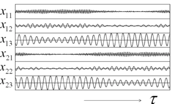
23. We can see from those figures that each phase di ff erence is asynchronous. Hence, we can say that double-mode and simultaneous oscillation is generated at the same time. Namely, the relationship between right and left oscillators is double-mode, while the relationship between above and below oscillators is asynchronous. Figure 4 shows the time waveforms of the six voltages. The time waveforms of x
11and x
21are double-mode, while x
12and x
22, x
13and x
23are also double-mode. We can confirm that the envelopes of the double-mode oscillations are synchronized in anti-phase.
- 76 -
Fig. 4. Time waveforms of xmn.αC1=0.5,αL1=0.3,αC2=0.4,αL2=0.2, γ=0.01,ε=0.055 andβ=3.14.
Fig. 5. Lissajous figures of six resonators. Horizontal: xmn. Vertical: ymn. αC1=0.5,αL1=0.3,αC2=0.4,αL2=0.2,γ=0.1,ε=0.055 andβ=3.14.
Figures 5, 6, and 7 show another example of the steady states obtained for di ff erent coupling parameter. The figure of x
11- x
21is synchronized in in-phase. But, the figure of x
12-x
21is synchronized in anti-phase, and the figure of x
13-x
23is double- mode.
IV. C onclusions
In this study, we have investigated the generation of syn- chronization phenomena observed from two inductively cou- pled simultaneous oscillators with three resonators. We could confirm the phenomenon that double-mode and simultaneous oscillation have generated at the same time. Namely, the relationship between right and left oscillators is double-mode, while the relationship between above and below oscillators is asynchronous.
R eferences
[1] J.Schaffner, “Simultaneous oscillations in oscillators,” IRE Transactions on Circuit Theory, Vol.1, pp.2-81, Jun. 1954.
[2] M.Kuramitsu and F.Takase, “Averaged potential analysis of multimode oscillators with hard operating conditions,” IEICE Technical Report on NLP , Vol.81, No.13, pp.1-10, Sep. 1981.
Fig. 6. Phase differences of six resonators.αC1=0.5,αL1=0.3,αC2=0.4, αL2=0.2,γ=0.1,ε=0.055 andβ=3.14.
Fig. 7. Time waveforms of xmn.αC1=0.5,αL1=0.3,αC2=0.4,αL2=0.2, γ=0.1,ε=0.055 andβ=3.14.
[3] M.Matsuki and S.Mori, “Asynchronous simultaneous oscillations in negative resistance oscillatory circuit containing periodically operating analog switch,” IEICE Technical Report on CAS, Vol.101, pp.81-87, Jun. 1993.
[4] M.Matsuki and S.Mori, “Asynchronous excitation phenomena in neg- ative resistance oscillatory circuit containing periodically operating analog switch,” IEICE Technical Report on NLP, Vol.94, pp.51-58, May 1994.
[5] C.Higashi and Y.Nishio, “Investigation of synchronization phenomena in coupled simultaneous oscillators,” Proceedings of NCSP’10, pp.113- 116, Mar. 2010.
[6] Y.Nishio, Y.Yang and Y.Uwate, “Synchronization phenomena in simul- taneous oscillators coupled by an inductor,” Proceedings of NCSP’11, pp.147-150, Mar. 2011.