Synchronization of Coupled Oscillators with Double Tetrahedrons as a Shared Triangular Face
Takahiro Nagai Hironori Kumeno Yoko Uwate Yoshifumi Nishio Dept. of Electrical and Electronic Engineering, Tokushima University,
2-1 Minamijosanjima, Tokushima, 770-8506 Japan Email:{nagataka, kumeno, uwate, nishio}@ee.tokushima-u.ac.jp
Abstract— This paper acquaints the synchronization of coupled oscillatory system with double tetrahedral forms as a sharing triangular face. We confirm the synchronization phenomena by measuring the phase differences between adjacent oscillators.
Also, we obtain the amplitude of each oscillator using the simulation results.
I. INTRODUCTION
Coupled oscillatory system is one of the most proper model to indicate the high-dimensional phenomena in natural science fields [1]-[7]. there are a lot of synchronization phenomena in natural environment. Therefore investigations of the cou- pled oscillatory systems about synchronization phenomena are reported in biology, physics and mathematics. Coupled oscillatory systems have various wave patterns and including wave propagations, clustering and complex patterns. Hence, various coupled oscillators were proposed, and the part of the mechanism of the non-linear phenomenon has been elucidated until now. However investigations on the complex coupled oscillatory networks have not been studied enough yet.
In our investigations, we use several van der Pol oscillators.
Van der Pol oscillators have been coupled in various form and investigated about their synchronization phenomena [8], [9].
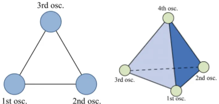
In particular, three coupled oscillatory system with a ring topology as shown Fig. 1 have made the very interesting results [10]. In this circuit system, each oscillator was coupled by an inductor and the number of coupled oscillators was an odd number. Then, we could not observe the synchronization phenomena with in/anti-phase states. That is to say, three- phase synchronization (phase shift: 120◦) is obtained for the
Fig. 1. Coupled van der Pol oscillators. (a) Three coupled oscillator. (b) Four coupled oscillator.
Fig. 2. Conceptual circuit model for tetrahedron form.
case of three oscillators by the effect of frustration. However, the three-phase synchronization was always observed stably in that system.
In our previous study, we have investigated several kinds of interesting synchronization phenomena in coupled oscillatory system which has stronger frustrations. We have researched four coupled van der Pol oscillators in the regular tetrahedron form as shown in Fig. 1(b). By computer simulation, we observed that the phase difference between adjacent oscillators changed and the synchronization was destroyed after the adja- cent oscillators synchronize with anti-phase. And the another study, synchronization phenomena in two coupled triangular oscillatory networks sharing a branch was investigated in [11].
In this case, we could observed synchronization that the phase difference of sharing branch is in-phase (phase difference: 0◦), and the other one between adjacent oscillators are synchro- nized with anti-phase (phase difference: 180◦).
This paper presents synchronization of coupled oscillators with double tetrahedrons as a shared triangular face. We show the our coupled oscillatory system in Fig. 2 which is used tetrahedral forms sharing a triangular face. We confirm the synchronization phenomena by measuring the phase differ- ences between adjacent oscillators.
II. CIRCUITMODEL
The circuit model is shown in Fig. 3(a). In this circuit model, two tetrahedrons oscillators are coupled by the triangular face and the fourth and the fifth oscillators have no connection.
In the computer simulations, we assume that the vk −iRk characteristics of nonlinear resistor in each oscillator is given by the following third order polynomial equation.
- 58 -
IEEE Workshop on Nonlinear Circuit Networks December 9-10, 2011
Fig. 3. Circuit model with double tetrahedrons. (a) Conceptual circuit model.
(b) Coupled structure.
iRk=−g1vk+g3vk3 (g1, g3>0), (k= 1, 2, 3, 4, 5).
(1) The normalized circuit equations are expressed as:
dxk
dτ =ε(1−xk2
)xk−(yak+ybk+yck+ydk)
dyak
dτ =1 4
{xk−ηyak−γ(yak+yn)}
dybk dτ = 1
4
{xk−ηybk−γ(ybk+yn)}
dyck
dτ = 1 4
{xk−ηyck−γ(yck+yn)}
dydk
dτ = 1 4
{xk−ηydk−γ(ydk+yn)} .
(2)
We use the following normalizations:
t=√
LCτ , vk =
√g1
g3
xk , iak=
√ g1C g3Lyak,
ibk=
√ g1C
g3Lybk, ick=
√ g1C g3Lyck,
ε=g1
√L
C, γ=R
√C
L, η=rm
√C
L,
(k = 1, 2, 3, 4, 5), where ε is the nonlinearity, γ is the coupling strength, η indicates the resistive component andyn denotes the current of neighbor oscillator on coupling resistor. In the computer simulations, we calculate the phase differences between adja- cent oscillators. Herermdenotes the internal resistance of an inductor.
III. SYNCHRONIZATIONPHENOMENA
We calculate Eq. (2)-(6) using the fourth-order Runge-Kutta method with the step size h= 0.002. In this simulation, we consider frequency errors ζ at the voltage equation. In other word, the voltage equations of the second, the third, the forth and the fifth oscillators are multiplied byζ(k= 2, 3, 4, 5),
Fig. 4. Attractor between adjacent oscillators (horizontal axis:xk, vertical axis:yk(k= 1,2, 3, 4, 5).
Fig. 5. The time waveform of the each oscillator.
we fix the frequency errors ζ2 = 1.001, ζ3 = 1.002, ζ4 = 1.003, ζ5= 1.004.
We show the simulation result of the synchronization phe- nomena in Fig. 4. In this figure, we show the attractor of each oscillator and the horizontal axis is the voltage of each oscillator, and the vertical axis is the electric current of each oscillator. These electric currents are summed the four currents yk =yak+ybk+yck+ydk and we set the parameters ε = 0.10,γ= 0.10 andη= 0.00010. Because we defineηto evade L-loop, we fix this value in these simulations. Next, the time waveforms of the voltage of each capacitor after sufficient time has elapsed are shown in Fig. 5. And the phase differences between the adjacent oscillators of this case is equal to the result. As a result, in the case of this circuit model, it was observed that the phase difference finally converged with the constant value. Also, this phase difference hardly varies even if we change the initial conditions. The case of parameter γ > 0.0660, the synchronization phenomena between each oscillator can be seen asynchronous.
When the coupling strength is strong, the phase differ- ences converge for in/anti-phase. Shared triangular oscillators are synchronized for in-phase but the shared oscillators are
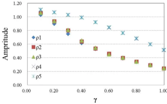
Fig. 6. Amplitude of voltage.
- 59 -
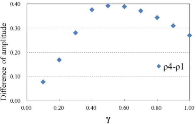
Fig. 7. Difference of amplitude.
synchronized with other oscillators for anti-phase. Also, We describe changes of the amplitude ρk of voltage in Fig. 6.
In this result, the amplitudes are divided into two groups that one of the groups is the shared oscillators and the other one is the remained oscillators. We can find that all of amplitudes decrease by varying the parameter γ. Figure 7 shows the difference of amplitude ρ4−ρ1, if the difference of the amplitude becomes big to some extent, each amplitude influences on the phase difference and each oscillator tends to converge for in/anti-phase.
IV. CONCLUSIONS
This paper has acquainted the synchronization of coupled oscillatory system with double tetrahedral forms as a sharing triangular face. We have confirmed the synchronization phe- nomena by measuring the phase differences between adjacent oscillators. Unlike the case only for the tetrahedron form, it was observed that the phase difference converged with certain values. Also, the coupling strength grew big, we could find that the amplitude of each oscillator decreased by using the simulation results.
REFERENCES
[1] L.L. Bonilla, C.J. Perez Vicente and R. Spigler, “Time-periodic phases in populations of nonlinearly coupled oscillators with bimodal frequency distributions,” Physica D: Nonlinear Phenomena, vol.113, no.1, pp.79-97, Feb. 1998.
[2] J.A. Sherratt, “Invading wave fronts and their oscillatory wakes are linked by a modulated traveling phase resetting wave,” Physica D: Nonlinear Phenomena, vol.117, no.1-4, pp.145-166, June 1998.
[3] G. Abramson, V.M. Kenkre and A.R. Bishop, “Analytic solutions for nonlinear waves in coupled reacting systems,” Physica A: Statistical Mechanics and its Applications, vol.305, no.3-4, pp.427-436, Mar. 2002.
[4] 4. Belykh, M. Hasler, M. Lauret and H. Nijmeijer, “Synchronization and graph topology,” International Journal of Bifurcation and Chaos, vol.15, no.11, pp.3423-3433, Nov. 2005.
[5] C.M. Gray, “Synchronous oscillations in neural systems: mechanisms and functions,” J. Computational Neuroscience, vol.1, pp.11-38, 1994.
[6] J. Cosp, J. Madrenas, E. Alarcon, E. Vidal and G. Villar, “Synchronization of nonlinear electronic oscillators for neural computation,” IEEE Trans.
Neural Networks, vol.15, no.5, pp.1315-1327, Sep. 2004.
[7] R. Stoop and C. Wagner, “Neocortex’s architecture optimizes computa- tion, information transfer and synchronizability, at given total connection length,” International Journal of Bifurcation and Chaos, vol.17, no.7, pp.2257-2279, 2007.
[8] T. Suezaki and S. Mori, “Mutual synchronization of two oscillators,”
Trans. IECE, vol.48, no.9, pp.1551-1557, Sep. 1965.
[9] Y. Uwate, Y. Nishio and R Stoop, “Synchronization in three coupled van der Pol oscillators with different coupling strength,” Proc. of NCSP’10, pp.109-112, Mar. 2010.
[10] Y. Uwate, Y. Nishio and R Stoop, “Synchronization in two polygonal oscillatory networks sharing a branch,” NDES 2010, pp.62-65, May. 2010.