DOCTOR THESIS
SHIBAURA INSTITUTE OF TECHNOLOGY
Energy-Efficient
Heterogeneous Wireless Communication
with Extended SDN-Controller
SEPTEMBER 2017
Acknowledgements
First of all, I would like to thank my supervisor Prof. Eiji KAMIOKA, who gave me the opportunity to join the “Hybrid Twinning Program” at Shibaura Institute of Technology and supervised me through my thesis. He has always been of great help, encouragement and supported me with everything I needed. Working at his lab was a pleasure since he gave me the freedom to find my own research interests and advised me in every possible way. This work would have never reached completion without his helpful discussions.
I am graceful to Prof. Shuji Kubota at Shibaura Institute of Technology (SIT), Prof. Shigeki Yamada at National Institute of Informatics (NIII), Prof. Hiroaki Morino and Prof. Takumi Miyoshi at SIT for serving on my oral committee. Prof. Kubota, who is my co-supervisor, has advised me both ideas and conducive comments. Prof. Yamada has provided me not only a systematic view of my study, but also instructive comments on every chapter of my dissertation. Prof. Miyoshi gave me useful comments from the SDN viewpoint. Prof. Morino gave me conducive comments on VHO.
Abstract
In the next generation of wireless networks such as the fifth generation (5G), different radio access technologies (RATs) will be integrated into each mobile device as a fundamental feature, aiming to connect any person using any device at anytime, anywhere. To allow the users to enjoy the ubiquitous connectivity, RATs are generally activated simultaneously. Therefore, the mobile device has to consume higher energy for the simultaneous activation of multiple wireless interfaces as well as the continuous connectivity. Although RATs co-exist in the same environment, they are designed heterogeneously. The technologies that offer high data rate are generally energy-consuming ones while low-energy technologies commonly provide low data rate. When the services run on the device do not always require high data rate, it is not an energy efficient way to keep using high-speed technology. If a low energy technology, i.e., Bluetooth, can be used in replacement of the energy-consuming one, i.e., Wi-Fi, the energy consumption of the wireless communication can be saved. It is obvious that the consumed energy will be saved most when the unused technology is turned off. To migrate between different technologies without disrupting any ongoing services, the network-layer connectivity must be maintained, or a vertical handover (VHO) is required.
The VHO process is generally controlled by a centralized control. In many occasions, the centralized control center does not function properly affecting the mobility management's execution. For instance, in catastrophic disasters like the East Japan Earthquake, crucial network infrastructures were destroyed, causing the centralized control to be isolated. Thereby, the VHO should be controlled by the mobile device itself to be aware of the environment. The mobile device typically navigates traffic through the firmware of the wireless network interface cards (WNIC) using their drivers, which are typically dependent on the vendors. To be aware of the vendors, the control of the traffic navigation between WNICs should not be relied on any modification of the WNICs’ drivers.
in a mobile device, a traditional SDN-controller (traditional-SDNC) become a local controller. The traditional-SDNC still directly controls a virtual OpenFlow switch, which turns WNICs into its ports. However, traditional-SDNC is deployed locally, it lacks the global view of the network topology and cannot navigate the traffic correctly. To support the traditional-SDNC in controlling traffic, an extended SDN-controller (extSDNC) is proposed.
To control the switch, a traditional-SDNC needs at least information of the network such as the network topology. To learn the network topology, the network information including IP and MAC addresses must be exchanged among the devices. Therefore, the first feature that needs to be enhanced for the traditional-SDNC is a controller-to-controller (C2C) communication. Since the traditional-SDNC’s design is to talk only with the networking devices, i.e., OpenFlow switches, the messages exchanged in a C2C communication must go through the switches. Unfortunately, in the OpenFlow specification, there is no option to allow a traditional-SDNC to send any messages through switches to another traditional-SDNC. The traditional-SDNC needs a network application (nwApp)to instruct the switches to forward and receive a message to another traditional-SDNC. Note that nwApp in SDN architecture is mainly to steer the switches through a traditional-SDNC. Therefore, it is recommended to use a non-SDN software, or an extended SDN controller (extSDNC), to play the role of exchanging C2C’s messages.
To perform a VHO smoothly, the VHO must be triggered properly. For this purpose, different VHO trigger algorithms are introduced for a different context. For instance, in disaster scenarios, VHO can be triggered based on speech pattern recommended by ITU-T to prolong the communication time for victims. In wireless multi-hop networks, VHO between an energy-consuming technology, i.e., Wi-Fi, and a low-energy one, i.e., Bluetooth, can be used to reduce unnecessary energy intermediate nodes spent to relay messages. In this case, VHO is triggered based on bandwidth utilization, i.e., Bluetooth’s capacity. In any case, experimental results have confirmed that data traffic was migrated smoothly from any direction between different wireless access technologies.
Contents
Contents ... IX List of Figures ... XIII List of Table ... XV List of Abbreviations... XVII
Chapter 1 Introduction ... 2
1.1 Motivation ... 2
1.2 Existing technologies constraints and challenges ... 4
1.3 The extended SDN-controller (extSDNC) ... 7
1.3.1 Traditional SDN architecture ... 7
1.3.2 The need of an extended SDN-controller developed separately from traditional-SDNC 8 1.4 Contribution and dissertation organization ... 10
Chapter 2 Design and feasibility of extSDNC ... 14
2.1 Design requirements... 14
2.1.1 extSDNC must work with any existing SDN controllers ... 14
2.1.1 extSDNC must be to monitor and control network interfaces ... 14
2.2 The design of extSDNC ... 15
2.3 Evaluation ... 17
2.3.1 Handover between Wi-Fi and Wi-Fi interfaces ... 18
2.3.2 Handover between Wi-Fi and Bluetooth interfaces ... 20
2.3.3 Handover when TCP and UDP traffic are transferred ... 22
2.4 Conclusion ... 26
Chapter 3 Communication between extSDNCs ... 28
3.1 Assumed network environment... 28
3.2 Mobile-controlled vertical handover management ... 29
3.3 Energy consumption model... 30
3.4 Evaluation ... 32
3.4.1 Mobile-controlled VHO management performance evaluation ... 32
3.4.2 Energy efficiency evaluation... 37
Chapter 4 VHO decision in heterogeneous wireless communication ... 42
4.1 Requirements for the proposed system ... 42
4.1.1 Assumptions in a disaster environment ... 42
4.1.2 Energy-efficient communications in disaster scenarios ... 43
4.2 Energy-efficient wireless communications algorithm ... 44
4.3 D2DHWC: Device-to-device heterogeneous wireless communication ... 48
4.4 Performance evaluation ... 50
4.4.1 Evaluation of energy-efficient communication ... 50
4.4.2 Evaluation of heterogeneous communication ... 54
4.5 Conclusions... 57
Chapter 5 VHO decision in wireless multi-hop network ... 58
5.1 Assumed wireless multi-hop network ... 58
5.2 Wireless multi-hop network management ... 59
5.3 Energy efficient wireless multi-hop network ... 60
5.4 Evaluation ... 61
5.4.1 Power consumption measurement ... 61
5.4.2 Energy consumption measurement on intermediate devices ... 63
5.4.3 Energy consumption measurement on supporter devices ... 65
5.5 Conclusion ... 66
Chapter 6 esVHO: energy-saving solution for wireless communication ... 68
6.1 esVHO design ... 68
6.1.1 Assumed non-interconnected environment ... 68
6.1.2 Design requirement ... 69
6.1.3 esVHO framework for non-interconnected environment ... 71
6.2 Performance evaluation ... 77
6.2.1 Experiment results ... 77
6.2.2 esVHO framework validation ... 80
6.2.3 Energy saving evaluation ... 83
6.2.4 Vertical handover evaluation ... 87
6.3 Conclusion ... 91
Chapter 7 Discussion ... 92
7.1 Energy efficient mobile-controlled VHO ... 93
7.1.1 VHO Information gathering ... 93
7.1.3 VHO execution... 95
7.2 Energy saving model ... 96
Chapter 8 Conclusion and Future work ... 98
List of Figures
Fig. 1.1: Traditional SDN Architecture... 7
Fig. 1.2: Organization of this dissertation ... 11
Fig. 2.1. SDN-controllers embedded in a mobile device ... 15
Fig. 2.2. Handover between Wi-Fi and Wi-Fi interfaces Testbed ... 18
Fig. 2.3. Packet Loss in Handover between Wi-Fi and Wi-Fi interfaces... 19
Fig. 2.4: Handover between Wi-Fi and Bluetooth interfaces Testbed ... 20
Fig. 2.5. Packet Loss Counts in Handover between ... 21
Fig. 2.6: Experiment topology ... 22
Fig. 2.7. FTP file transfer time ... 24
Fig. 2.8. Average execution time ... 24
Fig. 2.9. UDP packet loss and jitter ... 26
Fig. 3.1. Considered network topology ... 28
Fig. 3.2. Messages exchanged in a mobile-controlled VHO management ... 29
Fig. 3.3: Energy consumption model for the mobile-controlled VHO ... 31
Fig. 3.4. Experiment topology ... 33
Fig. 3.5. Handover delay measurement ... 34
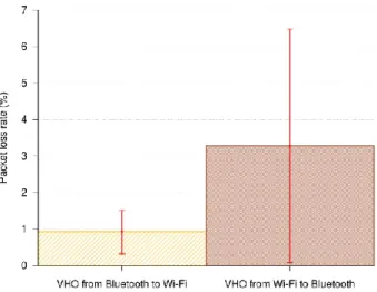
Fig. 3.6. Packet loss rate when handover between Bluetooth and Wi-Fi... 35
Fig. 3.7. File transfer time ... 36
Fig. 3.8: Energy consumption measurement setup ... 37
Fig. 3.9. Instantaneous power when wireless interfaces are off... 38
Fig. 3.10. Instantaneous power when using Bluetooth ... 38
Fig. 3.11: Instantaneous power when using Wi-Fi ... 39
Fig. 4.1. A vertical handover triggering algorithm ... 44
Fig. 4.2. Conversational speech model in ITU-T P.59... 46
Fig. 4.3. Handover execution ... 47
Fig. 4.4. Synchronization process ... 47
Fig. 4.5. Schematic of the sustainable heterogeneous communication network ... 49
Fig. 4.7: Energy saved when performing a vertical handover ... 52
Fig. 4.8. Energy saved by using proposed system ... 53
Fig. 4.9. Experiment topology ... 54
Fig. 4.10. Handover delay measurement ... 55
Fig. 4.11. End-to-end jitter of the robust heterogeneous communication network ... 55
Fig. 4.12. Packet loss rate of the robust heterogeneous communication network ... 56
Fig. 5.1. Wireless multi-hop network topology ... 58
Fig. 5.2. Controller to controller communication ... 59
Fig. 5.3. Handover triggering algorithm ... 60
Fig. 5.4. Measurement setup ... 61
Fig. 5.5: Power consumption when Wi-Fi is used for transmitting traffic ... 62
Fig. 5.6. Power consumption when Wi-Fi is used for receiving traffic ... 62
Fig. 5.7. Power consumption when Bluetooth is used for transmitting traffic ... 63
Fig. 5.8. Power consumption when Bluetooth is used for receiving traffic ... 63
Fig. 5.9: Energy consumed by the wireless communication when using proposed method ... 64
Fig. 6.1: Non-interconnected networks ... 69
Fig. 6.2: esVHO framework on a mobile device ... 71
Fig. 6.3. VHO timing adjustment mechanism ... 72
Fig. 6.4. Energy consumption transition ... 74
Fig. 6.5. Energy consumption transition when a handover from Bluetooth to Wi-Fi is performed ... 74
Fig. 6.6. Energy consumption model for esVHO ... 74
Fig. 6.7. Energy consumption measurement setup ... 78
Fig. 6.8. Energy consumption when only Wi-Fi is used ... 81
Fig. 6.9. Energy consumption when esVHO is being used ... 82
Fig. 6.10: Total energy consumption: measurement vs. simulation ... 82
Fig. 6.11. Energy consumption model for Bluesaver VHO ... 85
Fig. 6.12. Energy saving measurement ... 86
Fig. 6.13. Maximum energy saved when VHO happens frequently ... 86
Fig. 6.14. Handover from Wi-Fi to Bluetooth ... 88
Fig. 6.15. Handover from Bluetooth to Wi-Fi ... 89
List of Table
Table 2.1: Network state database ... 16
Table 2.2: Flow rules... 19
Table 4.1: Average power consumption of wireless network interfaces ... 51
Table 6.1 Definition of each parameter which shows consumed power... 75
Table 6.2 Average power consumption on wireless network interfaces ... 79
List of Abbreviations
ICT Information and Communication Technology
MIMO Multiple Input Multiple Output
AP Access Point
WLAN Wireless Local Area Network
PSM Power Saving Mode
IEEE Institute of Electrical and Electronics Engineers LR-WPANs Low-Rate Wireless Personal Area Networks
VHO Vertical Handover
IP Internet Protocol
MIH Media Independent Handover
SIP Session Initiation Protocol
OSI Open Systems Interconnection
WNIC Wireless Network Interface Card
RSSI Received Signal Strength Indicator
SDN Software-Defined Networking
extSDNC extended SDN-controller
traditional-SDNC traditional SDN-controller
SBI Soundbound Interface
NBI Northbound Interface
nwApp Network Application
C2C Controller-to-Controller
MAC Media Access Control
ARP Address Resolution Protocol
RTT Round-Trip Time
OVS Open vSwitch
XML eXtensible Markup Language
SSID Service Set IDentifier
RAM Random Access Memory
CPU Central Processing Unit
ICMP Internet Control Message Protocol
TCP Transmission Control Protocol
UDP User Datagram Protocol
FTP File Transfer Protocol
ADC Analogue-to-Digital Converter
D2DHWC Device-to-Device Heterogeneous Wireless Communications
US United States
DHS Department of Homeland Security
ITU-T International Telecommunication Union – Telecommunication
VoIP Voice over IP
CSMA/CA Carrier Sense Multiple Access with Collision Avoidance
RTP Real Time Protocol
QoS Quality of Service
PC Personal Computer
WPAN Wireless Personal Area Network
BU Bandwidth Utilization
DB Database
LTE Long-Term Evolution
Chapter 1 Introduction
1.1 Motivation
With the development of Information and Communication Technology (ICT), wireless access technologies and systems have been developed and deployed throughout the world, aiming to provide reliable high-speed wireless accesses from anywhere at any time. On that networks, different types of applications and services to deliver various media types including text, audio, videos, and images to end users have been introducing. To access such diverse multimedia contents, many types of affordable wireless devices including smartphones, tablets, embedded control systems and entertainment devices are emerging. As a result, the number of users that uses mobile devices to access applications and services wirelessly increases exponentially. In 2017, over sixty-five percent of the world’s population is mobile users as reported in [1]. The network traffic generated by wireless networks has also grown significantly. For example, web traffic comes from mobile devices is more than a half of the global web traffic. The growing data traffic and the continuity of the ubiquitous accesses have escalated the demand for energy consumption.
The escalation of energy consumption raises the cost of operation and maintenance. For example, when the data rate increases 1000 times [2], an equivalent increase of transmitting/receiving power would lead to an exponential growth of electricity bills and maintenance costs. To avert the escalation of energy consumption due to the data rate increased 1000 times, the energy efficiency should be improved 1000 times.
In general, energy efficiency can be improved on all technology layers including hardware design improvement, the network planning and deployment strategies, network operation, and management. Many efforts have attempted to give energy efficient hardware solution such as power amplifiers [4, 5], hybrid analog and digital beamforming structures [6, 7 and 8]. Other works consider the planning, deployment, and operation of the wireless networks. For example, the work in [9] analyzed the trade-off between energy efficiency and node densification. The work in [10] densified the number of deployed antennas in a MIMO system while considering the energy efficiency. Since the cost of improving the hardware design or changing the deployment of the network is high and mobile devices can communicate directly without relying on any existing infrastructure, i.e., access point (AP) in wireless local area network (WLAN), many researchers focus on increasing the energy efficiency of the wireless communication system by allocating the communication radio resources [11-15]. The resources are no longer be allocated for maximizing the amount of transmitting information. The considered factor is the amount of energy consumed to reliably deliver the maximized amount of information.
With a fixed infrastructure wireless network, the energy efficiency can increase by improving the power saving mechanism defined in each wireless technology. For example, Wi-Fi, which offers high-speed data rate, has a power saving mode (PSM) [16] that allows the clients to sleep more by buffering packets at the access point (AP). The performance of PSM can be improved as introduced in [17, 18 and 19] by extending the sleeping duration of Wi-Fi. However, Wi-Fi in sleep state still consumes more energy than low energy consumption technologies, i.e., Bluetooth, in the active state. Such an energy-consuming technology should be used less when it is unnecessary.
[23] is commonly used. Although Bluetooth is also optimized for low power consumption, it does not support high data rates, i.e., up to 1Mbps.
Therefore, when the application and services on the mobile devices do not require high bandwidth, high-speed technology, i.e., Wi-Fi, becomes an energy inefficient communication means. Just for example, bandwidth-hungry services such as video streaming do not always require high bandwidth utilization [24]. In this cases, a low-energy technology, i.e., cellular or Bluetooth, should be used in replacement of the energy-consuming one, i.e., Wi-Fi. When data traffic is migrated from one network to another, a vertical handover (VHO) is required to insure the quality, reliability, and continuity of all ongoing services.
The main focus of this dissertation is to save energy for the wireless communication when different types of data are continuously transferred with dynamic change of data rate by performing VHO. The energy saving mechanism must not affect the quality of the current connection as well as all running application and services. The mechanism should not rely on any existing infrastructures or any external supports. Also, it should not require any customization of existing hardware as well as a device driver, or not be depended on any specific hardware vendor.
1.2 Existing technologies constraints and challenges
i.e., the decision engine in [32], to generate a handover trigger and gather the network topology information.
In a non-interconnected environment, the wireless access networks are not connected, thus, the mobile devices have to perform a VHO fully by themselves. For this purpose, they have to control their data traffic navigation. Data traffic is typically navigated through the firmware of the wireless network interface cards (WNICs) using their drivers, which are dependent on the vendors. Thereby, the control of traffic navigation between WNICs commonly requires modification of the WNICs’ drivers [24, 37, and 38]. After having full control of data traffic navigation, to perform a VHO, mobile devices must collect enough information for the VHO decision and the VHO execution process. Not to rely on any external support, mobile devices should be able to exchange information to gather all necessary data. In addition, when two communicating devices have to perform a VHO to the same designated network, the VHO processes should be completed at almost the same time to avoid losing packets or interrupting ongoing application and services.
Without any modification of the WNIC’s driver, Software-Defined Networking (SDN) [39] is a potential candidate for controlling the WNIC using software, i.e., an SDN-controller. Unfortunately, the control in existing SDN architecture ends at the network switches or routers [70, 71]. To control the incoming and outgoing data traffic on WNIC of mobile devices, the SDN concept can be applied locally [24, 40, and 41]. However, in these approaches, the embedded SDN-controller, which becomes a local SDN-controller, operates passively behind a global SDN-controller. This is because local SDN-controller needs network-wide information such as network topology to correctly control the data traffic inside the devices. This information can be collected easily by the global SDN-controller as it has the global view of the network.
The key element in the previous works is the extSDNC. The next section, hence, will give an overview of extSDNC, highlighting the difference between traditional SDN-controller and extSDNC.
1.3 The extended SDN-controller (extSDNC)
1.3.1 Traditional SDN architecture
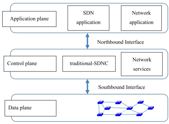
Software-Defined Networking (SDN) has emerged as a flexible way to control the network in a programmatic way. The core idea of SDN is to separate control plane and data plane. In the data plane, networking devices, i.e., switches, simply perform packet forwarding. The control function of network devices is executed by a software program called SDN-controller. The SDN architecture is initially designed in a centralized manner mainly for wired network, especially for data center deployments. The centralized approach allows the SDN-controller to have a global view of the network, hence, it can manage and operate the network with ease. For instance, in a wired network, the connection between any two end devices is a point-to-point full duplex link that can be controlled without modifying the devices.
Fig. 1.1: Traditional SDN Architecture
Application plane SDN
application
Network application
Control plane traditional-SDNC Network
services
Data plane
Northbound Interface
In SDN architecture, the control and data planes are decoupled as shown in Fig. 1.1. In the data plane, networking devices, i.e., switches, work as simple packet forwarding elements, thus sometimes the data plan is called forwarding plane. The control function of network devices is moved to an external element, the so-called SDN-controller. The traditional SDN-controller (traditional-SDNC) has two key functions. First, it is responsible for controlling or forwarding packets in the data plane. The packets are forwarded in a flow-based mechanism. In the mechanism, all the packets that match the criteria defined in one flow rule will be processed in the same way, forming a flow. To check the matching, when packets reach the networking devices, their header field values are taken out and are compared to the stored flow rules. The flow rules are typically defined by the traditional-SDNC and then are sent to the networking devices via the soundbound interface (SBI). Second, the traditional-SDNC collects status information from networking devices to offer a global view of the network to applications in the application plane. The traditional-SDNC communicates with the application via the northbound interface (NBI). The interface also allows the traditional-SDNC to listen to requirements from each network application (nwApp). After receiving the requirements, the traditional-SDNC interprets them into the instructions, which will be used to control the data plane.
1.3.2 The need of an extended SDN-controller developed separately from
traditional-SDNC
To control the switch, a lt-SDNC needs at least information of the network such as the network topology. To learn the network topology, the network information including IP and MAC addresses must be exchanged among the devices. Therefore, the first feature that needs to be enhanced for the SDNC is a controller-to-controller (C2C) communication. Since the lt-SDNC’s design is to talk only with the networking devices, i.e., OpenFlow switches, the messages exchanged in a C2C communication must go through the switches. Note that the lt-SDNC mainly uses OpenFlow protocol to talk with the switches. In the OpenFlow specification [48], there is no option to allow a lt-SDNC to send any messages through switches to another lt-SDNC. However, it is possible that a lt-SDNC instructs the switches to forward and receive a message, which is not generated by the lt-SDNC, to another lt-SDNC. Since network applications (nwApps) in SDN architecture is to steer the switches through a lt-SDNC. Therefore, it is recommended to use a non-SDN software, or an extended SDN-controller (extSDNC), to play the role of exchanging C2C’s messages.
In case a link failure occurs, the proposed system must perform a vertical handover to maintain the end-to-end connection. When performing the vertical handover, all the ongoing traffic are switched from one physical interface to another. This action requires the reconfiguration of the network to detach an access technology and attach to the other one. Since the lt-SDNC and nwApps are targeted at controlling the switches, the extSDNC should be involved in managing the physical network configuration. Besides, the change of physical interface will change the IP and MAC addresses in the packet’s header, hence, the system must ensure that any running application is not interrupted during and after the vertical handover process. Not to let the applications to detect the change of physical interface, the system needs to provide a virtual interface with unchanged IP and MAC addresses for them. To this end, the packets, which are exchanged between two end devices, must have those values in their header rewritten. SDN technology already offers the packet’s header rewriting feature. However, to handle ARP packets, the extSDNC is again required.
lt-SDNC, thus, it can be in charge of controlling the switch while waiting for the lt-SDNC to be recovered.
1.4 Contribution and dissertation organization
In this dissertation, the main contributions can be summarized as follows:
(1) An extended SDN-controller (extSDNC) was proposed to embed the SDN architecture into mobile devices, allowing them to well manage various types of incoming and outgoing traffic over different WNICs without relying on any external support or requiring modification of WNIC driver;
(2) The local SDN architecture was implemented using a real testbed;
(3) A controller to controller (C2C) communication means was proposed to allow extSDNCs on communicating devices to exchange information. The C2C communication means is also used for making decision whether or not to trigger a VHO in different scenarios;
(4) A VHO timing adjustment mechanism was proposed to enable the VHO processes on two communicating devices to be finished at almost the same time, reducing the VHO delay as well as the number of packet loss;
(5) An esVHO framework was proposed to improve the performance of extSDNC in term of reducing VHO delay and number of packet loss as well as saving energy.
(6) An energy consumption model was proposed based on direct measurement and was validated under realistic traffic.
The organization of the dissertation is illustrated in Fig. 1.2 and is described as follows:
Chapter 1: Introduction. The motivation and background of this study are represented in this
separately from traditional-SDNC was also concretely discussed. Finally, the summary of the key contributions in this research was also described in this chapter.
From chapter 2 to chapter 6, the design of extSDNC, the C2C communication means, the energy efficient VHO algorithm and the esVHO framework contributed in this study followed three phases of a VHO process are presented.
Chapter 2: Design and feasibility of extSDNC. This chapter describes the design of the
extSDNC and shows how its feasibility is confirmed. Specifically, the performance of extSDNC was evaluated under various protocols in a real testbed.
Chapter 3: Communication between extSDNCs. This chapter presents the C2C
communication between extSDNCs embedded on communicating mobile devices. The detail of the message sequences confirms that the VHO processes on two devices can complete at almost the same time, reducing packet loss as well as service interruption. In addition, the energy efficient model shows that performing VHO using extSDNC can save energy for the wireless communication.
1. Introduction
Information gathering
2. extSDNC embeded in a mobile device 3. Communicationbetween extSDNCs
Handover decision
4. VHO decision in heterogeneous wireless communication 5. VHO decision in wireless multi-hop network
Handover execution 6. esVHO framework 7. Discussion
8. Conclusion and Future work
Chapter 4 and Chapter 5 discuss the VHO decision in different scenarios. Specifically, in
Chapter 4, VHO is triggered based on network throughput, allowing victims in a disaster situation to have a device-to-device heterogeneous wireless communication. The performance of the wireless communication is evaluated using a testbed and the energy efficiency of the system is validated by direct measurement. Similarly, in Chapter 5, a triggering algorithm for energy efficient VHO in wireless multi-hop network is introduced to reduce the energy the intermediate nodes spend to relay messages. The communicating nodes also consume less energy by choosing the least energy-consuming interface for transfer.
Chapter 6: esVHO: energy saving solution for wireless communication. This chapter
describes how the number of packet loss generated by the VHO process is reduced by using the esVHO framework. Besides, the energy consumption model based on direct measurement results confirmed the effectiveness of the proposal in term of energy saving. Experimental as well as simulated results have confirmed that esVHO outperforms the others.
Chapter 7: Discussion. This chapter discusses the advantages as well as the opened issues of
the proposals in this dissertation.
Chapter 8: Conclusion and Future work. This chapter concludes the dissertation and outlines
Chapter 2 Design and feasibility of extSDNC
This chapter describes the requirement and the design of extSDNC in order to allow mobile devices to perform VHO fully by themselves.
2.1 Design requirements
2.1.1 extSDNC must work with any existing SDN controllers
As mentioned in section 1.3.1, a traditional-SDNC typically controls the packets that go through the networking devices, i.e., OpenFlow switches. The traditional-SDNC is commonly located separately from the switches and has a global network view including the network topology, link status, etc. Therefore, to control the packets, the controller only needs to talk with the switches. However, when a traditional-SDNC and an OpenFlow switch are embedded in one node of the network as shown in Fig. 2.1, the traditional-SDNC may not be able to have the global network view due to the network disconnection and it is unable to answer any requests from the switch. Therefore, the extSDNC must be able to support all existing traditional-SDNCs, which generally have their own design with different APIs, to operate locally on a mobile device.
2.1.1 extSDNC must be to monitor and control network interfaces
2.2 The design of extSDNC
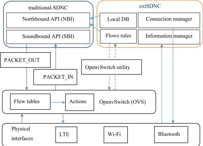
Figure 2.1 shows the control logic of a mobile device applied the SDN architecture. All physical interfaces of the device are configured to be ports of a software Open Flow switch named OpenvSwitch (OVS). The OVS navigates network traffic based on OpenFlow rules stored in the Flow tables. When a packet reaches the OVS, its header information is matched with the OpenFlow rules. If the switch finds that there is no available flow rule for the request, the OVS will ask the traditional-SDNC using OpenFlow protocol. For example, it sends a PACKET_IN message to the SDNC and waits for the answer. The traditional-SDNC will reply with a PACKET_OUT message to instruct the OVS to install or modify rules in the Flow tables. Based on the installed rules, corresponding actions are applied to all packets, which have the same header information.
traditional-SDNC
Soundbound API (SBI) Northbound API (NBI)
extSDNC
Flows rules Information manager Connection manager Local DB
PACKET_IN
Fig. 2.1. SDN-controllers embedded in a mobile device OpenvSwitch (OVS) PACKET_OUT
OpenvSwitch utility
Flow tables Actions
Wi-Fi Bluetooth
Physical
To support the traditional-SDNC to handle the switch requests as well as local network behavior, the extSDNC is designed with four components named “Local DB”, “Flow rules”, “Connection manager” and “Information manager”. The “Information manager” component is to collect network state and stores them in a local database called “Local DB”. For flexibility in the deployment, an XML format is picked as a storage. After that, the traditional-SDNC, which have no communication channel except the one with a switch, can read the network information at any time. If the collected information is big enough, the traditional-SDNC might have a sufficient knowledge of the network topology. It is possible because the extSDNC can exchange and update this database to any devices to which it connects. Table 2.1 shows the main content of the file, in which, all network configurations are described. For example, the tag Connection is to present the node name and the connection status from the local one to the other nodes. It has two attributes named Name and Status which are marked with X in Table 2.1. The second tag, Media, shows the method which the local node is using to connect to the outside. It has three attributes Name, ID and Key. The attribute Name shows the name of the connection, i.e., Wi-Fi or Bluetooth, while ID shows the SSID of the AP or the MAC address of the Bluetooth master and Key contains security string for authentication. On the third row, the tag Bridge describes information of the bridge which is a virtual interface and it has the same number of the attribute with the Interface tag which presents physical interfaces. The MAC and IP address for virtual and physical interfaces are recorded, however, these values are defaulted ones, they can be changed when the node talks with another node. The invited node normally needs to change its IP address to join the talk. The status of the interface can also be changed to ON or OFF depending on the interface which the node actives and establishes a connection.
TABLE 2.1:NETWORK STATE DATABASE
Tag name Attributes
Name Switch port IP MAC Status ID Key
Connection X X
Media X X X
Bridge X X X X X
Based on the collected information, the “Flows rules” component of the extSDNC prepares OpenFlow rules to actively ask the traditional-SDNC to instruct the OVS with new rules. The “Flows rules” component can play a role of a temporary controller when the traditional-SDNC has problems in controlling the switch. For instance, when the traditional-SDNC is frozen or being killed, the Open vSwitch [66] will have no controller to ask. In this situation, the extSDNC needs to be in charge of controlling the switch at least until the traditional-SDNC comes back. The “Flows rules” component can answer the switch with the prepared rules by utilizing a built-in utility of the Open vSwitch called ovs-vsctl.
The “connection manager” component is developed to be able to control any wireless interface. For instance, it can enable or disable an interface. It can also associate an interface with its network without user interaction. Thereby, it brings a simpler and easier way to maintain an ongoing session between two devices when the current physical connection is going to be lost. In theory, to maintain an ongoing session, the same local end-point IP and MAC addresses must be kept through the session. The applications here only see the middle interface created by the OVS. As a result, if the IP and MAC addresses of the middle interface are not changed, the change in the physical interface does not affect the upper applications. Note that wireless base stations generally only allow packets with the source MAC address of WNIC that has completed the initial handshake [49]. Consequently, on establishing a new connection, the destination sends out an ARP packet asking for MAC address of the new IP address. The extSDNC will automatically send the replies to these requests, however, only selective ARP requests are carefully answered to avoid security risks.
2.3 Evaluation
2.3.1 Handover between Wi-Fi and Wi-Fi interfaces
The goal of this experiment is to show the feasibility of the extended SDN controller in a handover in wireless networks and to provide sample flow entry configurations under different handover scenarios.
In this experiment, device 1, which is a mobile device equipped with SDN-controllers, is talking with a conventional mobile device via an AP as depicted in Fig. 2.2. The device 1 is equipped with two wireless interfaces in which one interface is active and the other is for backup purpose. Note that when a device has more than two Wi-Fi interface, any packets sent from the node are easily be looped among the interfaces, hence, they must be controlled by the OVS and the default network-manager service must be disabled. Switch port numbers port_wifi_A and port_wifi_B are assigned to the two interfaces, respectively while the switch port number of the OVS is “LOCAL”. The MAC address of the OVS is borrowed from one interface. It is assumed that the OVS and the Wi-Fi B interface have the same MAC address. On the other hand, the extSDNC collects this information and fills into the local database. It also gathers the information about the device 2 to which the SDN-based node connects. Based on the collected information, OpenFlow rules are described as shown in Table 2.2. When the active interface is Wi-Fi B, flow rules are simple as the OVS simply forwards the packet to corresponding ports. However, when the active interface is Wi-Fi A, the MAC address of the bridge and the active interface are different, thus, the IP and MAC address in the packet header must be rewritten. The mod-dl-dst and mod-nw-dst fields in the flow actions are used to rewrite the destination MAC and IP address in the packet header. For example, when device 1 sends a packet to device 2, the packet will go through the OVS and be encapsulated with the IP and MAC addresses of the OVS. To detect ICMP packets sent from device 1, the OVS checks
Fig. 2.2. Handover between Wi-Fi and Wi-Fi interfaces Testbed Device 1
Wi-Fi B
Device 2 Wi-Fi A
incoming packets to see if the packet type is ICMP, the input port in_put is “local” and the source MAC address dl-src is equal to the bridge MAC address bridge-mac. The switch then changes the source and destination MAC and IP addresses to the values of two physical interfaces as if the packets were exchanged between them. This is because a wireless client must associate with the AP before exchanging data. The association time sometimes lasts several seconds, thus, the experiment must be long enough to let the handover event occur during transferring data.
In the Testbed, device 1 sent 4000 ICMP packets to device 2 at the rate of 1ms and handovers took place randomly during the experiment. When a handover took place, the extSDNC activated the backup interface and installed new flow entries into the flow table. After the current interface was shut down, the flow of ICMP began running over the new interface. The number of packet loss was also observed in the inverted direction. Each experiment was repeated 30 times and the number of packet loss was shown in Figure 2.3. The figure shows that the highest packet loss rate was 0.3% when switching the ICMP flow from the interface B to the interface A. In an inverted way, there was less packet loss and the number of packet loss was more stable. This is because the interface B has the same MAC address with the bridge, hence, flow rules were simple and the system spent less time to switch the flow.
TABLE 2.2:FLOW RULES
Direction Flow rules Flow actions From interface A to B in_port=local in_port= port_wifi_B Output: port_wifi_B Output: local From interface B to A in_port = local, dl-src = bridge-mac, type = icmp in_port = port_wifi_A, dl-dst = wifi-A-mac, type = icmp mod-dl-dst=wifi-dst-mac, mod-nw-dst=wifi-dst-IP, mod-nw-src=wifi-A-IP, mod-dl-src=wifi-A-mac, output: port_wifi_A
mod-dl-dst=bridge-mac, mod-nw-dst= bridge -IP, output: LOCAL
2.3.2 Handover between Wi-Fi and Bluetooth interfaces
The goal of this section is to evaluate the performance of the system in the vertical handover between Wi-Fi and Bluetooth interfaces. Since two physical interfaces use different ways to connect, it is assumed that two devices are able to coordinate to switch traffic between them.
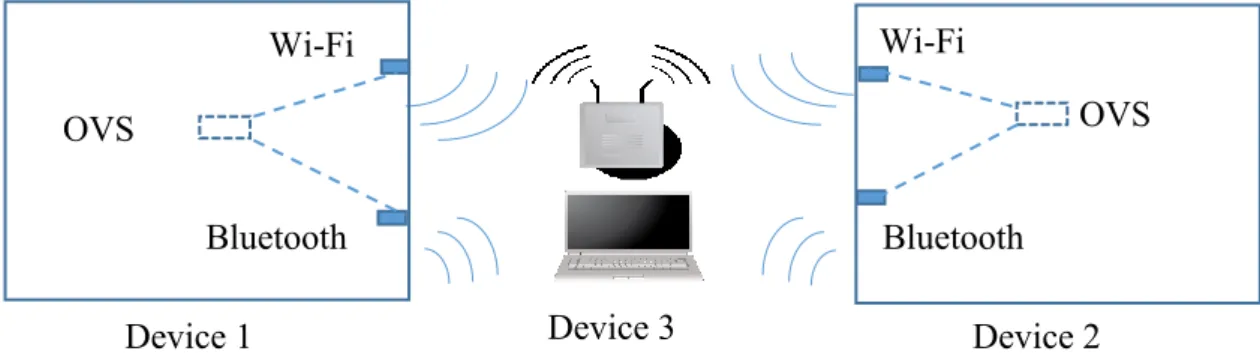
Figure 2.4 shows the scenario for the vertical handover experiment. In the figure, two devices equipped with one Wi-Fi and one Bluetooth interface are communicating. It is assumed that the nodes can be either member in the same Bluetooth piconet formed by another conventional mobile node or two wireless clients which connect to the same AP. All physical interfaces are controlled by the OVS and switch port numbers are assigned to them. The OVS chooses the
MAC address for the bridge, assumed that it takes the value of the Bluetooth interface. This information is collected and recorded in the local database which has the same structure as the one in the previous experiment. The system also uses the same way to define flow rules to rewrite IP and MAC address in the packet header. Note that the Wi-Fi interface has a higher speed than the Bluetooth one, hence, it is difficult to separate the number of packet loss because of reducing the connection bandwidth and the packet loss during handover. Consequently, in this experiment, the handover only happens in the direction from the Bluetooth interface to Wi-Fi interface. When the Bluetooth connection is going to be lost, i.e., two nodes are out of the Bluetooth communication range, the ongoing traffic is automatically shifted to the Wi-Fi connection.
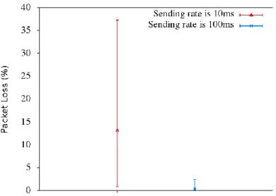
In the first experiment, 1000 ICMP packets were exchanged between two nodes at the rate of 10ms and handovers took place randomly during the experiment. The experiment was repeated 30 times with random handover and the number of packet loss are presented in Fig. 2.5. Figure 2.5 shows that the packet loss is up to 37.2%, or the maximum number of packet loss is 372 packets over 1000 sent ones. This rate is reduced when packets are sent with a slower speed. The highest rate of packet loss now is only 2.4% when the packet interval is 100ms. The results confirmed that the extSDNC enhanced the system resilience since it can automatically switch the traffic.
2.3.3 Handover when TCP and UDP traffic are transferred
This section is to validate the proposed system with TCP and UDP protocol, which are basic protocols for almost all network applications, in a real Testbed.
2.3.3.1
Experiment settings
The system has been evaluated using the network topology as illustrated in Figure 2.6. In the figure, two SDN-based mobile nodes equipped with one Wi-Fi and one Bluetooth interface are communicating in a Bluetooth piconet. For the Bluetooth connection, we disabled the built-in Bluetooth built-interface, as it only supports Bluetooth version 1.2. An external class 2 Bluetooth dongle is added to every node in order to test the system with the latest version of Bluetooth standard – Bluetooth v4.0. Regarding the Wi-Fi connection, any nodes already have a built-in Wi-Fi interface which is able to connect to 802.11n Wi-Fi networks. These physical interfaces on each node are under control of the Open vSwitch which is managed by the original SDN controller. As also shown in Fig. 2.6, two SDN-based nodes are communicating in a piconet via a master node. The master node in the piconet can be either an SDN-based mobile node or a conventional mobility device such as a tablet, a mobile phone or a laptop. Note that the master node provides IPs in a different subnet than the Wi-Fi interface. This is feasible as the packets, which are passed to an interface, are navigated by the flow rules in the flow table on the switch. Besides, the Bluetooth and Wi-Fi connectivity parameters such as Bluetooth MAC address, Bluetooth authentication key, Wi-Fi SSID and Wi-Fi authentication key, IP address of all
OpenvSwitch Bluetooth Wi-Fi Client 1 SDN-controllers OpenvSwitch Bluetooth Wi-Fi Client 2 SDN-controllers
Fig. 2.6: Experiment topology Master
physical interfaces are assumed to be already in the local database. Therefore, all association processes are automated. Based on the information in the database, OpenFlow rules are also defined.
2.3.3.2
TCP traffic load
The measurement procedure with TCP traffic load is as follows: Initially, node 1 downloads a file from node 2 in an FTP client-server manner (i.e., using WGET program to download the file through FTP protocol) via Bluetooth connection. After 5 seconds, a vertical handover procedure is invoked on each node. The point of time that the procedures are called can be
Fig. 2.7. FTP file transfer time
slightly different as the handover occurs only when the synchronization procedure verified that both nodes have already finished the association process. The experiment was repeated 30 times and all the transferred files were not corrupted. Note that the WGET program basically shows transfer times in seconds, thus, the “time” command is used to call the WGET program in order to allow a measurement with millisecond accuracy. The file transfer durations with the vertical handover are also compared with that duration when there is no handover as shown in Fig. 2.7. Figure 2.8 shows that the maximum transfer duration when a vertical handover occurs is 9.064 seconds while the minimum duration when there is no handover is 10.559 seconds. Note that the handover was triggered 5 seconds after the receiver began to download the file. This means if the handover detection lasts less than 6.5 seconds, the vertical handover still occurs in a soft handover manner or make-before-break.
For more detail of the vertical handover execution time, the time for Wi-Fi association, OpenFlow rules installation and Network configuration were measured separately as given in Fig. 2.8. Note that the handover procedure is written in Python [50] so it is not difficult to get the time of execution of a block of code by using existing Python’s modules, i.e., “time” module can provide various functions for manipulating clock time. The figure shows that the average time of the whole execution process is 1.122 seconds at the client side and 1.232 seconds at the server side. However, the average time of the handover delays, which affect the running applications, including the time for installing OpenFlow rules and configuring the network at the client and server is 0.156 seconds and 0.184 seconds respectively. These values can be reduced by running processes in parallel. The difference between client and server is caused by the synchronization as the starting points of the handover procedure on two nodes are different. The experiment results have confirmed the feasibility of the SDN-based vertical handover system with a TCP traffic load. Moreover, it shows that the performance of the system can be measured in detail with a picosecond deviation.
2.3.3.3
UDP traffic load
and jitter, the system was evaluated with UDP traffic load. The experiment time was also set to 10 seconds.
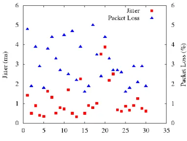
The measurement was conducted by using the Iperf tool. Firstly, an Iperf server is started on node 2 listening for incoming requests. Then, an Iperf client, which is enabled on node 1, attempts to send UDP traffic to the Iperf server. On both nodes, a vertical handover is triggered randomly while UDP traffic is being sent. The experiment was repeated 30 times and the measured results are shown in Fig. 2.9. The figure shows that the highest packet loss rate was 5% with 0.8ms jitter delay. Although the packet loss rate varies from 1.6% to 5%, the jitter is mostly less than 1ms. The results have confirmed the feasibility of the system with UDP traffic load. Furthermore, the evaluation suggests that the SDN-based system is a promising solution to maintain ongoing session of UDP-based applications during such a vertical handover.
2.4 Conclusion
The goal of this work is to allow mobile devices to perform VHO without any external support and extSDNC has been proposed. In the system, the SDN-controllers were embedded in each mobile device to collect network state and gave the traditional-SDNC the knowledge about the network topology by storing information in a local database. The performance of the system was evaluated under different scenarios. The evaluation results confirmed that communicating
Chapter 3 Communication between extSDNCs
In the previous chapter, the proposed extSDNC can support mobile devices to perform VHO based on their own recorded information, i.e., local measurement executed by themselves. However, it cannot guarantee that the VHO processes on both communicating devices finish at the same time. When they complete the VHO process at the different point of time, their connection will be interrupted. If the connection is interrupted in a long time, a lot of packets will be lost, hence, the quality of ongoing services cannot be guaranteed. To address this issue, a mobile-controlled VHO management is proposed to synchronize the VHO process on each device, minimizing the number packet loss.3.1 Assumed network environment
The considered scenario in this work is shown in Fig. 3.1. In the figure, two mobile devices, which are equipped with extSDNC described in the previous chapter, are communicating with each other. On each device, Wi-Fi and Bluetooth are available and the interference between them is assumed to be minimized. Basically, the devices use Wi-Fi technology to connect to the other via an access point (AP) or in an ad-hoc manner. Bluetooth technology is used as a backup one. It is also assumed that they are al-ways able to join a Bluetooth network. However, the Wi-Fi network and Bluetooth network are not interconnected.
Wi-Fi
Bluetooth
Device A Device B
3.2 Mobile-controlled vertical handover management
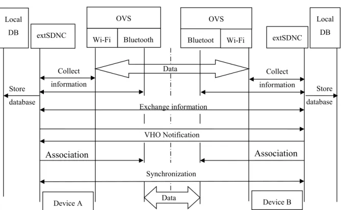
The mobile-controlled VHO management process here follows a three-phase procedure as illustrated in Fig. 3.2. As can be seen from the figure, the messages are exchanged only between two communicating devices. There is no external element involves in the control of the VHO process. The information for the VHO is collected and exchanged when two devices start communicating. When the devices decide to perform VHO, a simple message exchange procedure is executed, aiming to shorten the VHO delay with the cost of a few packet loss. The detail of the message sequence is as follow:
In the system discovery phase, the extSDNC, described in the previous chapter, on the mobile devices collects all the necessary information to make a decision whether or not to trigger VHO from the current access technology to the other. The collected information includes the local information of the device such as battery level, MAC and IP addresses as well as the information from the network side like access point properties, throughput, round-trip time (RTT). The information collected by each device is stored in a local database and is exchanged
Store database OVS Wi-Fi Bluetooth OVS Wi-Fi Bluetoot h Synchronization Association Association Data Data VHO Notification Exchange information Collect information Collect information Store database
with other devices. If there is no updated information, they exchange the information only one time right after their communication starts. Both traditional-SDNC and extSDNC can retrieve information from the database. However, only the extSDNC can add or modify the data in the database. Based on the collected information, the extSDNC makes a decision whether or not to trigger a VHO in the second phase. In this chapter, the VHO decision is made simply based on the total throughput Btotal. If the Btotal is smaller than a threshold BThres, the extSDNC will
decide to perform a VHO from Wi-Fi to Bluetooth. Otherwise, it connects two devices via a Wi-Fi connection. When the VHO decision is made, the extSDNC notifies the extSDNC on the other device of the decision and which technology is going to be used. Once both sides receive the VHO notification, the VHO procedure starts. The extSDNC activates and associates the backup wireless interface with its network. When the association process has finished, two devices must synchronize with the other in a similar way to the TCP 3-way handshake (SYN, SYN-ACK, and ACK). The synchronization process is to let the new wireless technology on two devices be available at almost the same time, hence, the packet loss will be reduced. After that, the extSDNC can tell the traditional-SDNC to instruct the switch to navigate the traffic to the new interface.
3.3 Energy consumption model
Let NB and NW denote the number of packets traveled over Bluetooth and Wi-Fi, respectively.
Also let RB and RW denote the average data rate in the network of Bluetooth and Wi-Fi,
respectively. The duration times used for Bluetooth and Wi-Fi are TB and TW, respectively, and
the system takes T seconds to send the total N packets as illustrated in Fig. 3.3. The energy consumption of the wireless communication E is the total energy consumption when each wireless technology is being used and is expressed by equation (1):
The duration time TB and TW can be calculated by the following equations if there is no packet
loss:
NB + NW = N (2) NB/RB + NW/RW = T (3)
From equation (2) and (3), we can calculate TW and TB as follows:
TW = NW / RW = (RBRWT - RWN) / (RB - RW) RW (4) TB = NB / RB = (RBRWT - RBN) / (RW - RB) RB (5)
The energy consumption of the wireless communication is minimal if the device uses Wi-Fi in the shortest duration. The shortest time TWmin is achieved when the VHO process from Wi-Fi
to Bluetooth and the service start at the same time. After that, only Bluetooth is used (Fig. 3.3). The TWmin is also the total execution time needed to perform a VHO from Wi-Fi to Bluetooth
called TVHO-WB. The minimal energy consumption Emin when using the mobile-controlled VHO
management is calculated as follow:
Emin = PWTWmin + PBTB = PWTVHO-WB + PBTB (6)
Although the device can successfully perform the VHO from Wi-Fi to Bluetooth to save energy, it has to switch back to Wi-Fi in some cases. For example, if the required data rate of
RW
RB
Fig. 3.3: Energy consumption model for the mobile-controlled VHO T
TW TB
the communication is higher than Bluetooth capability, i.e., 1Mbps, the device needs to switch the connection back to Wi-Fi to ensure the quality of running services. In the worst case, the device has to perform another VHO from Bluetooth to Wi-Fi right after finishing the handover from Wi-Fi to Bluetooth. In this case, the time period the device has been using Bluetooth corresponds to the total execution time to perform the VHO from Bluetooth to Wi-Fi (T VHO-BW). The maximal energy consumption Emax when using the mobile-controlled VHO
management is calculated as follow:
Emax = PWTW + PBTBmin = PWTW + PBTVHO-BW (7)
Since it takes TVHO-WB to perform a handover from Wi-Fi to Bluetooth and TVHO-BW to perform
a handover in the inverted direction, the number of successful VHO in the duration T is the quotient in the division given in the equation (8):
NVHO = T / (TVHO-WB + TVHO-BW) (8)
The minimal energy consumption when there is NVHO VHO occurred is:
EN = PWTW + PBNVHOTVHO-BW (9)
3.4 Evaluation
3.4.1 Mobile-controlled VHO management performance evaluation
3.4.1.1
UDP traffic load
To observe the handover delay and the packet loss rate, UDP is selected as the transport protocol because it provides a unidirectional communication, thus, lost packets are not retransmitted.
The testbed in this evaluation is illustrated in Fig. 3.4. The figure shows that two mobile devices are placed within the communication coverage of a Wi-Fi and Bluetooth networks. In the evaluation, Iperf [51] is used to generate a UDP flow toward the direction from device A to device B.
As mentioned in the previous chapter, the OVS is used to provide a virtual interface between an application and physical interfaces. Since the application only sees the virtual interface, it does not notice the change of physical interfaces. On the other hand, physical interfaces play the role of switch ports. The OVS navigates traffic that comes in and goes out of the interfaces by OpenFlow rules, which are created by the SDN controller and are stored in OVS’s flow table. The time taken to install OpenFlow rules is named TOFrules. Note that the physical
interface can be used after it is activated and associated with its network. This process takes
TNWconfig seconds. The difference between the end time of configuring network and that of
installing OpenFlow rules is defined as handover delay. The delay is the source of packet loss. For instance, if OVS finishes installing OpenFlow rules before the physical interface is configured, the traffic following the OpenFlow rules is sent to a physical interface, which has not been ready yet. Alternatively, if the new interface is ready, however, the OpenFlow rules is not installed, the traffic is not sent to it.
Access point
Fig. 3.4. Experiment topology Wi-Fi coverage
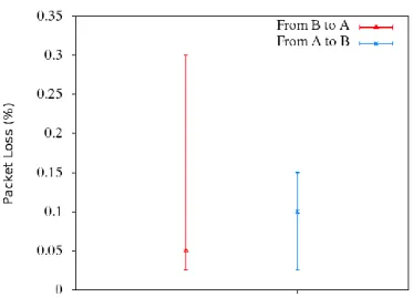
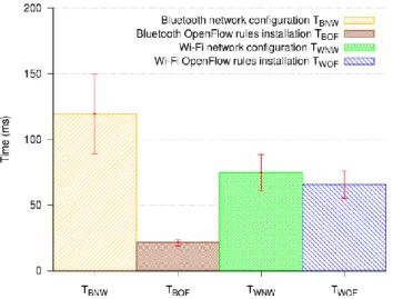
The measurement procedure is as follows: Firstly, device A with the role of a server starts Iperf in server mode and waits for incoming requests. On device B, an Iperf client then attempts to establish a connection with the Iperf server. While a 100 Kbps UDP traffic is being sent, a VHO occurs randomly. The delays were captured at the same time with measuring the packet loss rate in the previous experiments. The procedure was repeated 50 times and the measured results are shown in Fig. 3.5 and Fig. 3.6. The figure 3.5 shows that the network configuration duration TBNW and the OpenFlow installation duration TBOF of Bluetooth are 119.45ms and
21.34ms on average, respectively. The handover delay is as long as 98.11ms, causing 3.5% packets loss on average as shown in Fig. 3.6. The packet loss rate is relatively high, however, mainly below 7%, even if the traffic was switched from high data rate network to a lower one. In the inverted direction, a delay was inserted before executing install OpenFlow rules, reducing the handover delay to 18ms on average. As a result, the packet loss is only 1% as given in Fig. 3.6. The obtained results confirm that the shorter delay is, the fewer packets are lost. Moreover, the handover delay can be reduced by reducing the difference between TWOF and TWNW. The
handover delay is as small as 18ms with 1% packet loss rate can support real-time services.
3.4.1.2
TCP traffic load
The goal of this experiment is to verify the feasibility of the proposed system in maintaining the continuity of the service. In addition, the obtained results will be used to calculate the total execution time to perform VHO from Wi-Fi to Bluetooth and vice versa. To this end, a vertical handover during an FTP file exchange session has been observed. The average date rate of Bluetooth and Wi-Fi are also measured when there is no handover.
The measurement procedure with TCP traffic load is as follows: Initially, a program named WGET on device A tries to download a file from device B, on which an FTP server is running, via Wi-Fi connection. When the program begins, a vertical handover procedure is also invoked
on both devices. The total execution time has been captured. The experiment was repeated 30 times and all the transferred files were not corrupted.
The file transfer durations with the vertical handover are also compared with that duration when there is no handover as shown in Fig. 3.7. Figure 3.7 shows that it takes 10.93±0.28 seconds to transfer an 894KB file using Bluetooth. The data rate of the Bluetooth connection is 83.88±2.07 KBps. If Wi-Fi is used, that duration is only 3.57±0.27 seconds. The data rate of the Wi-Fi connection is 257.87±18.89KBps. When a VHO from Bluetooth to Wi-Fi occurs, the file transfer time is 5.77±0.94 seconds. In the inverted direction VHO, the file transfer time is 6.62±1.12 seconds. From the collected values, the average value of TWmin and TBmin can be
calculated using equation (3) and (4), respectively:
TWmin = (RBRWT - RWN) / (RB - RW) RW
= (83.88*257.87*6.62 – 257.87*894) / (83.88 – 257.87)257.87 = 1.95s
TBmin = (RBRWT - RBN) / (RW - RB) RB
3.4.2 Energy efficiency evaluation
3.4.2.1
Experiment setup
The energy consumption of wireless communication with and without a VHO has been measured by using a real testbed illustrated in Fig. 3.8. On the left of the figure, the mobile device is a Linux computer (Core 2 Duo @2.26 GHz processor and 2GB RAM, Ubuntu 14.04 64-bit). The device connects to Wi-Fi and Bluetooth networks using USB-based Wi-Fi and Bluetooth adapters, respectively. The adapters are connected to a current monitoring circuit before being attached to the mobile device. The output signal of the monitoring circuit is converted to a digital signal via an analogue-to-digital converter (ADC). The digital signal is then sent to the signal analysis device. The signal analysis device is a computer in which a small program is running to capture and save the digital signals.
3.4.2.2
Energy consumption measurement
In this evaluation, each device only uses one wireless technology at almost any given time, the other technologies are turned off. A technology is called “off” when it is not attached to any network. Therefore, the technology still consumes energy even it is turned off. The instantaneous power consumed in “off” state of Wi-Fi and Bluetooth has been measured and the results are given in Fig. 3.9. As shown in the figure, the average power of Wi-Fi PWi-Fi-off
and Bluetooth PBluetooth-off in the “off” state are 400.75mW and 37.25mW, respectively.
To examine the power consumption by each technology, device A and device B exchange file using FTP protocol. When two devices use Wi-Fi, Bluetooth is turned off and vice versa. The measured results are shown in Fig. 3.10 and Fig. 3.11. Fig. 3.10 shows the instantaneous power
PB when the device uses Bluetooth. As shown in the figure, Bluetooth only consumes 82.24mW
on average. The total average power of the wireless communication when using Bluetooth is:
PWireless-B = PB + PWi-Fi-off = 82.24+ 400.75 = 482.99mW
Fig. 3.9. Instantaneous power when wireless interfaces are off
Fig. 3.10. Instantaneous power when using Bluetooth
PWi-Fi-off
PB
PBluetooth-off
Similarly, Fig. 3.11 shows the instantaneous power when the device uses Wi-Fi PW. As shown
in the figure, Wi-Fi consumes 605.05mW on average. The total average power of the wireless communication when using Wi-Fi is:
PWireless-W = PW + PBluetooth-off = 37.25+ 605.05 = 642.30mW
Fig. 3.11: Instantaneous power when using Wi-Fi
3.4.2.3
Energy saving estimation
Assume that a service S last T=15s, the average power of the wireless communication when using Wi-Fi is:
PW = PWireless-WT = 642.30*15 = 9634.5mJ
The average power of the wireless communication when using Bluetooth is:
PW= PWireless-BT = 482.99*15 = 7244.85mJ
During the duration T, the maximal and minimal average power by using the mobile-controlled VHO management are calculated by using equation (6) and (7), respectively:
Pmin = PWireless-WTWmin + PWireless-B(T - TB)
Pmax = PWireless-BTBmin + PWireless-W(T - TBmin)
= 482.99*3.41 + 642.30 (15-3.41) = 9091.25mJ
The number of VHO can be occurred is the quotient in the division given in the equation (8):
NVHO = (T / (TWmin + TBmin))
= (15 / (1.95+3.41)) = 2
The minimal power consumed when there are two successful VHO occurred during the duration T is calculated using equation (9):
PN=2 = PWireless-W (T - NVHOTBmin) + PWireless-BNVHOTBmin
= 642.30*(15-2*3.41) + 482.99*2*3.41 = 8548.01mJ
From the estimated results, the power consumption by using the proposed mobile-controlled VHO management can save from 5.64% to 21.58% the power consumed by using Wi-Fi. The results also show that, even in the worst case, multiple successful VHO can save energy at least 11.28%.
3.5 Conclusion
Chapter 4 VHO decision in heterogeneous wireless
communication
The chapters show that it is feasible that mobile devices equipped extSDNC can perform a VHO fully by themselves. However, when to trigger the VHO process has not been discussed yet. Therefore, this chapter proposes a VHO trigger algorithm and a device-to-device heterogeneous wireless communications (D2DHWC) network to allow mobile devices to communicate, without a doubt, by using different wireless access technologies, i.e., Bluetooth or Wi-Fi. The considered scenario is a disaster situation in which the essential network infrastructures could be destroyed interrupting the communication among the victims and isolating them with the outside. Fortunately, multiple wireless technologies built in a single mobile device enables the exploration of different network access, thus, it is highly possible to utilize these technologies to form a heterogeneous wireless communication. Such a heterogeneous communication means is useful, especially in disaster scenarios, because having an uncorrupted and timely information exchanging means is critical for affected victims to survive or to connect to the outside world.