Corrosion Protection of Zinc Rich Paint
Coating on Steels
by
Azizul Helmi Bin Sofian
Graduate School of Engineering and Science
I, AZIZUL HELMI BIN SOFIAN, declare that this thesis titled, ‘COROSSION PRO-TECTION OF ZINC COATING’ and the work presented in it are my own. I confirm that:
⌅ This work was done wholly or mainly while in candidature for a research degree
at this University.
⌅ Where any part of this thesis has previously been submitted for a degree or any
other qualification at this University or any other institution, this has been clearly stated.
⌅ Where I have consulted the published work of others, this is always clearly
at-tributed.
⌅ Where I have quoted from the work of others, the source is always given. With
the exception of such quotations, this thesis is entirely my own work.
⌅ I have acknowledged all main sources of help.
⌅ Where the thesis is based on work done by myself jointly with others, I have made clear exactly what was done by others and what I have contributed myself.
Signed:
(AZIZUL HELMI BIN SOFIAN)
Certified by:
(PROF. KAZUHIKO NODA)
Date:
Abstract
Graduate School of Engineering and Science
Doctor of Philosophy
by Azizul Helmi Bin Sofian
Special attention has been paid since late 1950s to the studies aimed at improving and betterment the application of means of corrosion protection of metals as one of the methods for saving natural resources and increasing the durability of machines, building structures and other equipment. In order to protect metals against corrosion, coating is one of the promising method that can be employed. At the same time, insufficient attention has been given to the mechanism aspects of evaluating the efficiency of the protective coating. Recognising that there exist significant shortcomings in currently available information on corrosion mechanism, we are motivated to investigate the anti-corrosive protection by zinc rich paints (ZRP) using the commercial paints in the market. The research work was structured by coating metallic substrate with two di↵ent kind of ZRP with zinc content of 74 wt.% and 96 wt.%. Based on this coated materials, three main studies; specifically on corrosion performance in corrosive agent, comparison in di↵erent concentration of corrosive agents and evaluation on protective coating using electrochemical impedance spectroscopy (EIS).
2. The second study deals on the evaluation of coated samples in two di↵erent con-centration of corrosive agents, 0.5 and 1.0 M NaCl solution. The electrochemical behaviour were investigated based on polarization measurement, open circuit po-tential and electrochemical impedance spectroscopy (EIS). To confirm our coating is stable in thickness, SEM observation on the cross-section was conducted. The performance of the coating with di↵erent coating thickness varied particularly in coating system of 74 wt.%-ZRP. Using Stean-Greary equation, the polarization resistance (Rp) was determined from the Tafel plots and we also calculate the
cor-rosion rate (Vcorr in millimetre per year) . In 0.5 M NaCl solution, coating system
with 96%-5 shows the lowest corrosion rate. Coating systems with 74%-ZRP do performed well, and remarkably sample with 5 layers show the best performance in that system. There was a correlation between zinc content and corrosion re-sistance performance. Film thickness of the coated samples with 74% probably a↵ected the electrochemical properties and the corrosion resistance performance.
”Whoever has not thanked people, has not thanked God,” said the Prophet Muhammad (PBUH).This thesis is the results of the collaboration of many people. I am honored to have studied in Shibaura Institute of Technology with great number of people who contributed in assorted ways to the research and the making of the thesis deserved special mention. It is a pleasure to convey my gratitude to them all in my humble acknowledgement.
First and foremost, I praise to God, the Almighty, on whom ultimately we depend for sustenance and guidance. Second my sincere thank to the eminent supervisor Professor Dr. Kazuhiko Noda who has supported me throughout this reserach with his patience and knowledge while allowing me the room to work on my way and without him this doctorate thesis, would not have been completed or written. One simply could not wish for a better and friendlier supervisor.
In various laboratories and workshops, I have been aided for many years in running the equipment. The smooth running of the Materials Chemistry laboratory is much more an exemplification to my e↵ort. Prof. Dr. Kazuhiko Noda gave useful guidance in my research about zinc rich paint coating and its electrochemical behaviors. I also want to extend my deepest gratitude to the Defense Committee Members, Prof. Hideki Katayama from National Institute for Materials Science (NIMS), Prof. Akito Takasaki, Prof. Masato Murakami and Prof. Kentaro Kyuno for their guidance.
In my daily work, I have been blessed with a friendly and cheerful group of fellow col-leaugues and sta↵s. The Department of Materials Science and Engineering has provided support and equipment I have required to produce and complete this thesis. I am very grateful that Ministry of Higher Education of Malaysia (MOHE) and Universiti Malaysia Pahang (UMP) have funded my studies. Finally I thanked my parents, Haaizah Ahmad and Sofian Hakimi, for loving and supporting me throughout all my studies at Shibaura Institute of Technology.
Declaration of Authorship i Abstract iii Acknowledgements v List of Figures ix List of Tables xi Abbreviations xii Symbols xiii 1 Introduction 1
1.1 Motivation and Objectives . . . 2
1.2 Thesis Outline & Contributions . . . 3
1.2.1 Chapter 4: Corrosion Performance of ZRPs on mild steel in 0.5 M NaCl solution . . . 3
1.2.2 Chapter 5: Comparison of corrosion resistance in di↵erent concen-tration solution . . . 3
1.2.3 Chapter 6: EIS characterisation of ZRP coating . . . 4
1.2.4 Chapter 7: Conclusions & future works . . . 4
2 Background Theory 5 2.1 Zinc rich paints . . . 5
2.1.1 Introduction to zinc rich primer. . . 5
2.2 Corrosion of steel . . . 6
2.3 Corrosion of coated steel . . . 8
2.5 Corrosion protection by zinc rich paints (ZRP) . . . 13
2.5.1 Electrochemical impedance spectroscopy . . . 15
2.5.2 Equivalent circuit model . . . 16
3 Apparatuses and Experimental Methods 18 3.1 Substrate Pre-Treatment. . . 18
3.2 Spray Painting technique . . . 18
3.3 Surface morphology and Composition by Scanning Electron Microscope (SEM) . . . 19
3.4 Electrochemical Polarization Curve Measurements . . . 20
3.5 Electrochemical Impedance Spectroscopy . . . 21
4 Corrosion Performance of ZRPs on mild steel in 0.5 NaCl solution 24 4.1 Background . . . 24
4.2 Experimental . . . 25
4.3 Results and Discussion . . . 26
4.3.1 Adhesion test . . . 26
4.3.2 Cross-section morphologies . . . 27
4.4 Open Circuit Measurements . . . 28
4.5 Current density inhibition model . . . 31
4.6 Chapter Conclusion . . . 32
5 Comparison of corrosion resistance in di↵erent concentration solution 36 5.1 Overview . . . 36
5.2 Experimental . . . 38
5.2.1 Materials and experimental set-up . . . 38
5.2.2 Characterization of ZRP coating . . . 38
5.3 Results and Discussion . . . 39
5.3.1 E↵ect of concentration in NaCl solution . . . 39
5.3.2 EIS measurement . . . 46
5.4 Chapter Conclusions . . . 49
6 EIS characterisation of ZRP coating 52 6.1 Background . . . 52
6.2 Experimental . . . 53
6.3 Results and Discussion . . . 53
6.3.1 SEM analysis . . . 53
6.3.2 Corrosion potential with immersion time. . . 54
6.3.3 EIS analysis during immersion in corrosive agent . . . 57
6.4 Chapter Conclusions . . . 63
7 Conclusions & Future Works 64 7.1 Conclusion of Research Work . . . 64
7.2 Future Works . . . 65
7.2.1 Supplementary evaluation measurements. . . 65
A List of Publication 67
2.1 Pourbaix diagram for iron in water . . . 7
2.2 Schematic of a blister . . . 8
2.3 Schematic diagram of undercutting corrosion . . . 9
2.4 Basic approach of corrosion mechanism modeling; (a) before reaching the electrolyte to the metallic substrate and (b) after initiation of corrosion process due to electrolyte percolation . . . 16
2.5 Circuit configuration with corresponded Nyquist plots. . . 17
3.1 Commercial zinc rich paint . . . 19
3.2 Schematic diagram of coated sample . . . 20
3.3 The FE-SEM fitted with EDAX capability. . . 21
3.4 Actual measurement setup . . . 22
3.5 Polarization and electrochemical impedance measurement system . . . 23
4.1 Cross-cut test after spraying process (Initial state). The stain left on the sticky tape after the cross-cut test is shown on the hand left side . . . 27
4.2 Cross-cut test after immersion in 0.5 M NaCl for 1 week. The stain left on the sticky tape after the cross-cut test is shown on the hand left side . 27 4.3 Cross-section of SEM micrograph of 1 layer coating and distribution of Zn, Fe and C at initial stage. . . 28
4.4 Cross-section of 1 layer coating specimen (a) and 5 layers coating specimen (b) . . . 29
4.5 Variations in corrosion potential with time for samples coated with 74wt.% ZRP exposed in 0.5 M NaCl solution at ambient temperature.. . . 31
4.6 Variations in corrosion potential with time for samples coated with 96 wt.% ZRP exposed in 0.5 M NaCl solution at ambient temperature. . . . 32
4.7 Polarization measurement result for pure iron, zinc and coated samples in 0.5M NaCl solution . . . 33
4.8 Polarization measurement result for coated samples with 74% ZRP in 0.5M NaCl solution . . . 34
4.9 Suggested current density inhibition model . . . 35
5.1 SEM microstructure of coated samples for (a) 74%-1, (b) 74%-3, (c) 74%-5 40 5.2 SEM microstructure of coated samples for (a) 96%-1, (b) 96%-3, (c) 96%-5 41 5.3 The polarization test was carried out for ZRP coated samples in (a) 0.5 M and (b) 1.0 M NaCl solution . . . 42
5.4 Evolution of the free corrosion Ecorr with immersion time for 74%-ZRP coated samples . . . 43
5.5 Evolution of the free corrosion Ecorr with immersion time for 96%-ZRP
coated samples . . . 45
5.6 Nquist diagrams for coated samples of (a) 74% and (b) 96% in 0.5 M NaCl solution . . . 47
5.7 Bode plot for (a) 74% and (b) 96% as a function of di↵erent coating thickness. . . 48
5.8 Nquist diagrams for coated samples of (a) 74% and (b) 96% in 1.0 M NaCl solution . . . 49
5.9 Bode plot for (a) 74% and (b) 96% as a function of di↵erent coating thickness. . . 50
6.1 A schematic figure of coated sample . . . 54
6.2 SEM micrograph of zinc coating samples before and after immersion in 0.5 M NaCl solution for 7 days (a) 74%-before test (b) 74%-after test (c) 96%- before test (d) 96%-after test . . . 55
6.3 Evolution with immersion time of the corrosion potential of the ZRP coating system . . . 56
6.4 EIS data resulted from specimens in various immersion time in 0.5 M NaCl solution . . . 58
2.1 Types of blister . . . 8
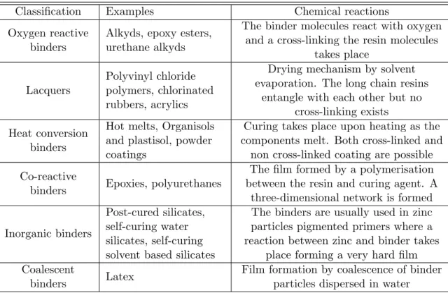
2.2 Classification scheme of binders according to their chemical reactions . . . 12
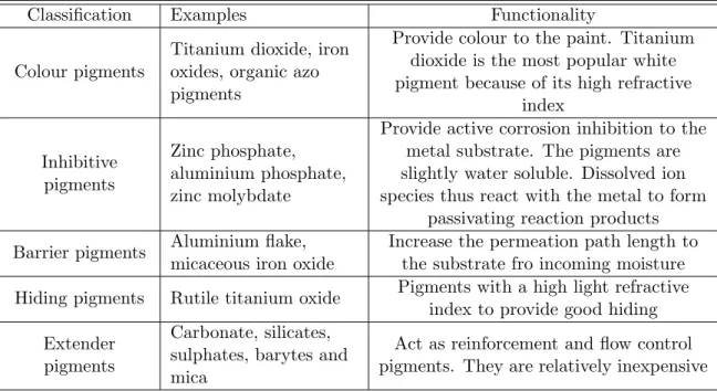
2.3 Classification scheme of pigments according to functionality . . . 13
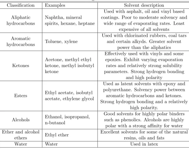
2.4 Classification scheme of solvents with a description of their application range. . . 14
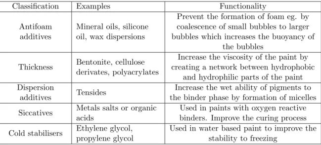
2.5 Classification scheme of additives according to functionality . . . 15
4.1 Adhesion properties of ZRP coatings after spraying process (Initial state) 26
4.2 Adhesion properties of ZRP coatings after immersion in 0.5 M NaCl so-lution for a week . . . 27
5.1 Average of coating thickness after spraying process . . . 39
5.2 Electrochemical parameters obtained in di↵erent NaCl solutions of the coated samples . . . 44
6.1 Fitted values of the parameters of EEC for 96 wt.% when immersed in 0.5 NaCl solution . . . 62
EEC Electrochemical Equivalent Circuit
Fe Iron
Fe(OH2) Ferum Hydroxide
Fe2O3 Ferric Oxide
H2O Water
NaCl Sodium Chloride O2 Oxygen
SEM Scanning Electron Microscopy
Zn Zinc
ZRP Zinc Rich Paint
C absolute capacitance F Cdl double layer capacitance F
I current A
Qcc sn⌦ 1
Qf constant phase element of coating flm⌦
Qdl constant phase element of double layer⌦
Rc resistance of charging circuit⌦
Rct charge transfer resistance⌦
Rf resistance of coating film⌦
Rs resistance of solution or electrolyte⌦
Ydl pre-factor of constant phase element Qdl sn⌦ 1
Z⇤ complex electrochemical impedance⌦ Z0 real part of electrochemical impedance⌦ Z00 imaginary part of electrochemical impedance⌦ Zc impedance of capacitor C ⌦
Zq impedance of constant phase element Q ⌦
Zr impedance of resistor R ⌦
! angular frequency rads 1
Introduction
The application [1] of zinc rich paints (ZRP) metal substrates is a very efficient ap-proach of corrosion resistance protection. They are used in many aggressive media such as sea water, marine and industrial environments. Today, thousands of industrial man-ufacturers depend on paint or coating for long lasting strength, protection and improve productivity. The main area zinc has been depicted to be more e↵ective than other coatings types. Furthermore, the current Clarke number of zinc is 0.004% exception-ally very small value and the needs in reducing zinc consumption is very crucial [2]. As the global economy is expanding at a decent pace, manufacturing and construction development in BRICs countries and other major developed countries the usage of steel keep expanding. Therefore, the demands of zinc rich paint, zinc plating application are growing everyday. Compared to electroplating, not only the consumption of zinc can be reduced, power saving and shortening the manufacturing time also can be expected by using the paint. The protection of steel with epoxy based zinc rich paint is based on the general principle of cathodic protection by metallic zinc in contact with metal substrates. It is a common fact that in order to achieve a long life coating system, a zinc primer needs to be applied as the first coat. For solvent based zinc rich paints, it seems to be established that, at least at the beginning of immersion, zinc particles provide [3, 4]. Then, a long term protection develops due to the formation of zinc corrosion products, reinforcing the barrier e↵ect of the paint [5].
The metallic zinc content in the dry film is a very important parameter to be emphasized in the technical specifications of zinc rich paints. However, as observed by Lindquist et al. [6] this parameter is not the only factor determining the performance of this kind of paint. For example, Fragata [7] Del Amo [8] and Pereira et al.[9] verified that the chemical nature of the binder and the zinc particle size are also very important. The zinc particle (spherical or lamellar shape, or a combination of both shape) is dispersed
in an inorganic (usually orthosilicates) or organic binder (usually epoxies) [10]. These particles must be in electrical contact between themselves and the metallic substrate in order to secure a well established electrical conduction within the coating. In such condition of percolation, a galvanic coupling is created between zinc and the metal substrates which is nobler than zinc. Then, zinc can preferentially dissolve, acting as sacrificial pigment, and allowing a cathodic protection of the metal substrate. Many studies [11, 12, 13, 14, 15, 16, 17, 18, 19] exist in literature and relate the protection mechanisms and degradation processes of such coatings. Physico-chemical properties and corrosion resistance of solvent based zinc rich paints strongly depend on pigment volume concentration (PVC), shape and size of zinc particle [4,20]. In common liquid ZRP, zinc usually introduced as spherical particles with mean diameter ranging from 5 to 10 µm. To ensure good electrical contacts between zinc pigments and the steel substrates, a high pigment concentration is required (usually above 60 wt.% by volume in solvent based zinc rich paints) [20]. A major drawback of classic solvent based paint is the emission of volatile organic compounds (VOC), which contribute to atmospheric pol-lution. Since the 1970s, powder coatings are often preferred because they are composed of dry thermosetting powder (without organic solvent) and more environment abiding.
Another type of zinc rich paint was introduced in the middle of 1990s in the automative industry with the intention of imparting weldability to organic coating [21]. The steel sheets were joined partly with each other at some sites during assembly into the auto-mobile body. Since such overlapped areas of steel sheets were difficult to be treated with paint or phosphate solutions, they became highly susceptible to corrosion. As a solution for this problem, cavity wax spray was employed to seal overlapped sites of steel sheets to prevent corrosive factors from approaching the joint sites. However, this method caused low productivity and higher production costs. In consequence, pre-coated steel sheets with paints that allow the welding of coated metal was proposed as an alterna-tive to overcome the problem. Much e↵ort has been invested to improved the corrosion resistance and weldability of the coating incorporating.
1.1
Motivation and Objectives
rich paint with epoxy based with 90 wt.% zinc, the volume concentration of the zinc will be approximately 60 wt.%, due to the di↵erence in specific gravity. Due to the lower zinc volume concentration usually found in epoxies and the insulating and protecting properties of the epoxy binder. one may ask whether zinc epoxy based coating systems are more susceptible to degradation in corrosive environments. Moreover, percolation and porosity are a↵ected by low zinc content which means that e↵ectiveness and interest of these ”zinc rich” coatings can be discussed. The corrosion behaviours of zinc rich paint with various thickness ranging from 10µm to 50µm, in two types of zinc rich paint with zinc contents of 74 wt.% and 96 wt.% was investigated to find out key factors of corrosion mechanism. In addition, the cathodic protection ability of zinc rich coating on metal substrate was evaluated.
1.2
Thesis Outline & Contributions
1.2.1 Chapter 4: Corrosion Performance of ZRPs on mild steel in 0.5
M NaCl solution
The chapter discusses on the preparation of coated samples using commercial ZRPs with di↵erent thickness. The corrosion behaviors/performances of zinc rich paint (ZRP) applied on steel substrates under NaCl solution environment were investigated by us-ing electrochemical measurements, scannus-ing electronic microscopy (SEM) and energy dispersive X-ray spectroscopy (EDX) and the results are presented in this chapter.
1.2.2 Chapter 5: Comparison of corrosion resistance in di↵erent
con-centration solution
1.2.3 Chapter 6: EIS characterisation of ZRP coating
Characterization of coated ZRP as anti-corrosive coating for metallic substrate using EIS is presented in this chapter. The performance of the materials was investigated practi-cally based on two di↵erent types of commercial ZRP, 74 wt.% and 96 wt.% with three di↵erent kind of thickness using open circuit potential and electrochemical impedance spectroscopy measurements. Comparison of these samples in di↵erent duration of im-mersion was also carried out and is presented in detail in this chapter. By utilizing EIS measurement, superior performance of ZRP in severe corrosive media could be under-stood deeply, as we fitted our data using the suggested electrical equivalent circuit.
1.2.4 Chapter 7: Conclusions & future works
Background Theory
In this chapter introductory theory will be elaborate to give the reader a deeper un-derstanding of the basic concepts of zinc rich paints and the application of zinc rich paints in anticorrosive paint systems for the protection of steel. The theory section is divided into 4 sections, each with their own subject area. Section 2.1 will be discussing general aspects of zinc rich paint, section 2.2 describes basic corrosion theory and mech-anisms, and 2.3 describes type of corrosion. Sections 2.4 describes the composition and formulation of anti-corrosive paint systems.
2.1
Zinc rich paints
This section will describes the basic chemical and physical characteristic of zinc rich paint with silicate and epoxy based. In particular, the chemical structure and its importance for di↵erent physical and chemical properties are presented.
2.1.1 Introduction to zinc rich primer
What is a zinc rich primer and how is it possible to protect bare metal from corrosion?
Zinc rich primer besides being a good barrier to oxygen and water may also protect the metal galvanically. For betterment in corrosion resistance the conductivity of the coating should be high and provide necessary conductivity for galvanic protection. High concentration of zinc, contributes to the film or coating’s porosity and its poor internal adherence. The coating of silicate base of ZRP frequently do not bond well to each other and it is better to coat the metallic substrate using an organic zinc-rich paint. Inorganic zinc primers and, to a lesser extent, organic zincs have been e↵ective in moderating
corrosion in extremely aggressive environment such as seashore and marine environ-ment.Their pricing is tied to the current price of zinc in the markets. Paint formulators have used variety of additives to reduce the occurrence of pinholes and cracks. The major problem is air entrained in the metallic substrate during the paint application. Although most of the air escapes from the paint without causing problems, a compelling quantity remains as tiny bubbles until the film is in its final stages of drying process. There-fore, to achieve maximum performance, most researchers attempt to coat the metallic substrate with thin coat, in order to allow the coat to dry fast without occurrence of cracks. In many environments the presence of pinholes in film or coating does not result in excessive corrosion. This surprise is probably due to high surface tension of solution, causing it form droplets rather than flowing on hydrophobic resin surfaces. However, in certain device, for example in tank lining work, pinholes cannot be tolerated [22]
While zinc silicate is a typical ”new building” coating, organic zinc rich paint is more of a maintenance primer. The epoxy base primer is far more easy to apply in higher thickness without cracking and can be applied with conventional airless spray, while alkali silicates normally need special equipment. Organic zinc rich coatings are not as electrically conductive as inorganic zinc rich coatings, thus, they have lower level of galvanic protection. We need to remind here that, organic zinc rich paints do not require as high a level of blast cleaned metallic surface as do inorganic coatings and they are easier to handle even for layman [23].
2.2
Corrosion of steel
Corrosion of steel is a well known problem, and can be recognized by the formation of red rust on the surface. In order for steel to corrode and form rust, anodic and cathodic reaction must take place. In the anodic reaction iron is oxidized and forms divalent cation Fe2+ with the liberation of two electrons (reaction 2.1). In reality, the most frequent cathodic reaction is the reduction of oxygen, as shown in reaction2.2
F e ! F e2++ 2e (2.1)
O2+ 2H2O + 4e ! 4OH (2.2)
Figure 2.1: Pourbaix diagram for iron in water
F e2++ 2OH ! F e(OH)2 (2.3)
Since oxygen dissolves readily in water, there is normally an excess of it. A further reaction with the formation of the well known red rust can therefore take place as shown in reaction 2.4
4F e(OH)2+ O2+ 2H2O ! 2F e2O3· H2O + 4H2O (2.4)
The stability of iron may be depicted by means of a Porbaix diagram. Figure2.1shows the Pourbaix diagram for iron substrate in water at 30 C
with an ion molarity of 1.0⇥10 6. As depicted on Figure 2.1, iron is only immune at a
potential below -0.65V. Above the immune area, iron will corrode in acidic environments with the formation of F e2+ or F e3+. In neutral environments, iron will have tendency to form oxides normally as F e2O3 or F e3O4. In strongly alkaline environments, iron
will corrode and form either F eO2 or HF eO2.
2.3
Corrosion of coated steel
The protective nature of corrosion resistance paint system is only valid for a given time and the destruction of the paint coating will eventually take place leaving free passage entrance for corrosive agents to penetrate towards metal substrates. normal failure mechanisms related to organic coatings include blistering and under cutting corrosion, which are fatal for the protective behaviour of the coating and chalking or fading, which are less risky. Blister paint are formed when water and other corrosive agents percolate the paint coating during time of wetness. Access of corrosive agents cause a corrosive reaction to take place underneath the coating and cause the paint film to swell, as illustrated in Figure 2.2. As the blister grows, it often be condusive to combine with other blister can be formed according to Table 2.1.
The osmotic blister is most common and is created near contaminants on the metal surface. An osmotic blister is the ordinary and created contaminants vicinity on the metal surface. An osmotic blister is conceived when water percolate the paint and
Figure 2.2: Schematic of a blister
Table 2.1: Types of blister
dissolves soluble substances in the paint. This produce a dense fluid beneath the paint which is drawn to the solution outside the paint by osmosis. The blister is developed as an attempt to equalize the density between these two fluids. [24]. Undercutting corrosion is developed near scribe or sheared edges as illustrated in Figure2.3. The corrosion will normally occur either by a chemical reaction in the interface between substrate material and paint, or by corrosion of the substrate metal itself. Both situations will decrease the adhesion, or unfavourable case, completely disconnect the paint film. The mechanism of undercutting corrosion can be described as a crevice corrosion scenario. Crevice corrosion is characterized by the presence of a small local anode and a large external cathode. Formation of an acidic environment and gaseous hydrogen in the crevice will further accelerate the corrosion [25]
Another kind of crevice corrosion is often present on painted aluminium and it is known as filiform corrosion. Filiform corrosion is initiated near defects and mechanical damages in the paint from which fine passageways containing corrosive products are spread in a smeared pattern. The mechanism behind filiform corrosion is directed by an active ”head”, which acts as an anode, while the ”tail” and the surrounding regions act as a cathode. A potential di↵erence of 0.1 to 0.2V is generally obtained between the head and tail region. The presence of oxygen is crucial for the maintenance of cathodic reactions, and therefore the motivation behind the mechanism of filiform corrosion. The cathodic reactions take place in the tail region, which is supplied with oxygen and condensed vapour through cracks and crevices in the coating. The head of the filament is filled with floating flakes of opal aluminium gel which are moving towards the tail region. Reactions between aluminium ions (Al3+) and hydroxide ions (OH ) will also take place in the tail region, producing aluminium trihydroxide (Al(OH)3) and aluminium
oxide (Al2O3). Filiform corrosion is generally dependent on the ratline humidity and the
quality of the applied surface treatment. Serious attacks appears in warm coast regions, where high salinity and high relative humidity increases the development of filiform corrosion. Filiform corrosion is only present in the atmosphere and occurs especially at a relative humidity of 85% to 95%. [26]. Cathodic protection of steel by means of sacrificial anodes (eg. zinc) or impressed current can result in cathodic disbondment which decreases the adhesion of the paint coating. The loss of adhesion between the paint and substrate material, is caused by formation of cathodic reaction products (eg. OH ) near flawed areas in the paint coating. Cathodic protection thus increases the risk of disbandment since cathodic polarised steel surface has a higher exposure to cathodic reactions. A model for the mechanism of cathodic disbandment is illustrated in figure, with the presence of cathodic reaction products beneath the paint coating.
Studies of the mechanism behaviour have shown that production of hydroxyl ions is the primary cause of cathodic disbondment. A direct proportionality is present between the OH concentration and the rate of disbandment. It is believed that the generated hydroxyl ions interact with the paint and thus weaken and break the bonds between the paint and the steel substrate. The oxygen concentration in the environment is another factor that enhances the risk of cathodic disbondment [27]
2.4
Anti-corrosive paint
An introduction to general aspects of paint composition and properties is needed in order to understand the mechanism of anti-corrosive paint systems. Paint is a complex formulation based on many di↵erent components which contribute to the overall effi-ciency of the system. This section describes the di↵erent components and their mode of operation.
2.4.1 What is paint?
The composition of paint can generally be divided into four main components: binder, pigment, solvent and additive. The binder is the backbone of a paint system and is therefore used to classify the system.
Generally, organic solvent based paint can be divided into two groups: physically drying paint and chemically curing paint. This categorisation concerns the action of film for-mation and describes whether the transition from liquid to solid state takes place either by evaporation or by chemical reaction.
Physically drying paints form a film exclusively by evaporation of solvents. The binder molecules have therefore the same composition and size both before and after solidifica-tion of the film. The mechanism of physically drying paint is physical process where the solvents evaporate and leave behind long chains of resin molecules, which pack together and form a coherent plastic film. Chemically curing paint is based on a curing mecha-nism where the film formation takes place by a chemical reaction between the binder and a curing agent. The final binder molecules in the dry film are therefore di↵erent from the initial binder molecules. The final binder molecules are much bigger and contain a high degree of cross-linking, forming a strong and non-reversible paint film [28].
A description of the four main components is given in the following four sub-sections. Each section describes the most common components, their mechanism and application.
2.4.2 Binders
The binder is an essential component that provides uniformity and coherence to the paint system. It holds the pigments together when a dry film is formed, and provides adhesion to the substrate material. The type of binder often determines the durability of the final product. The ability of a binder to form a dense and tight film is directly related to its molecular weight and complexity. Binders with a high molecular weight often tend to form film by evaporation, while low-molecular binders generally will form film by a reaction in situ. A way to classify a binder is according to its chemical reactions. Table
2.2lists some important binders, their grouping and chemical reactions.
2.4.3 Pigments
are also an import an additive for corrosion protection, film reinforcement, coverage and adhesion. In anti-corrosive paint systems, pigments mainly provide protection by one or more of the following mechanism; inhibition of corrosion, passivation of substrate metal, barrier against water permeability and cathodic protection. Certain pigments also elevate heat, abrasion, acid or alkali resistance to the final dry film. Important properties for all pigments are particle size and shape, wet ability by the binder and bulking. Some important pigments, their grouping and functionality are listed in Table
2.3.
2.4.4 Solvents
Solvents are volatile liquid substances with the purpose to dissolve solid paint fractions, reduce the viscosity and make the paint fluid for satisfactory appliance. After applica-tion, the solvent must evaporate to allow the coating t cure and achieve hardness. If a solvent has low volatility it can cause runs and sags in the drying coating film. In contradiction, solvents can not be too volatile and cause solvent pops, loss of gloss, dry spray, poor surface wetting and penetration, poor film flow and inhibit cure. A blend of di↵erent solvents is therefore normally used in order to achieve optimum properties. Solvents are usually categorized according to their chemical composition. Table 2.4list some important groups of solvents, their advantages and disadvantages.
Table 2.2: Classification scheme of binders according to their chemical reactions
Classification Examples Chemical reactions Oxygen reactive
binders
Alkyds, epoxy esters, urethane alkyds
The binder molecules react with oxygen and a cross-linking the resin molecules
takes place
Lacquers
Polyvinyl chloride polymers, chlorinated rubbers, acrylics
Drying mechanism by solvent evaporation. The long chain resins
entangle with each other but no cross-linking exists Heat conversion
binders
Hot melts, Organisols and plastisol, powder coatings
Curing takes place upon heating as the components melt. Both cross-linked and
non cross-linked coating are possible Co-reactive
binders Epoxies, polyurethanes
The film formed by a polymerisation between the resin and curing agent. A
three-dimensional network is formed
Inorganic binders
Post-cured silicates, self-curing water silicates, self-curing solvent based silicates
The binders are usually used in zinc particles pigmented primers where a reaction between zinc and binder takes
place forming a very hard film Coalescent
binders Latex
2.4.5 Additives
The final components in a paint system is the additives which normally make less than 1% of the entire paint formulation. Additive are used to balance the paint fluid and modify di↵erent physical and chemical properties such as viscosity, surface and interfacial tension, brightness and curing time. Addition of additives is only done when necessary since unwanted consequences on the paint properties are likely to obtain. The most common additives are listed in Table 2.5with an explanation of their function.
2.5
Corrosion protection by zinc rich paints (ZRP)
The application of zinc metal particles for corrosion protection has been examined for more than 50 years [29]. This section will reviewed di↵erent protection mechanisms which are proposed by a number of researchers. According to several studies, zinc rich paints (ZRP) are well known as efficient organic coatings to protect metallic substrates from corrosion. Marchebois et al. [30] has reported solvent based ZRP with mixture of zinc pigment varies from 50 or 70wt.%. The zinc concentration was well reported with liquid ZRPs and for the third formulation, conductive pigments (carbon blacks) were added. Then, their electrochemical behaviours wee compared using electrochemical impedance spectroscopy (EIS) and micro-Raman spectroscopy. They found that poros-ity and electrochemical behaviour was intimately related to the conductive pigments presence in the coating. Two coatings presented behaviours which related to zinc bare
Table 2.3: Classification scheme of pigments according to functionality
Classification Examples Functionality
Colour pigments
Titanium dioxide, iron oxides, organic azo pigments
Provide colour to the paint. Titanium dioxide is the most popular white pigment because of its high refractive
index Inhibitive pigments Zinc phosphate, aluminium phosphate, zinc molybdate
Provide active corrosion inhibition to the metal substrate. The pigments are slightly water soluble. Dissolved ion species thus react with the metal to form
passivating reaction products Barrier pigments Aluminium flake,
micaceous iron oxide
Increase the permeation path length to the substrate fro incoming moisture Hiding pigments Rutile titanium oxide Pigments with a high light refractive
index to provide good hiding Extender
pigments
Carbonate, silicates, sulphates, barytes and mica
metal during a short period but not real cathodic protection and e↵ective percolation were o↵ered. This is due to the low zinc content, but the shape and the size of the zinc dust have strong influence. Marchebois et al. also discussed the influence of ad-dition of conductive pigments like carbon blacks on the corrosion behaviour of ZRPs coated steel in artificial sea water [31]. Two di↵erent e↵ects were pointed out, first, an increase of the porosity induced by carbon addition and a galvanic action between zinc and carbon pigments. The performance of the powder coatings, strongly improved if the carbon amount was sufficient, compared to the one reported for solvent based zinc rich paints. Then Jagtap [32]and Gergely [33, 34] improved the corrosion protection using zinc rich paints with various amounts of dispersed polypyrole-deposited alumina monohydrate particles . They focused on investigation various hybrid formulations in order to gain valuable improvement by certain zinc rich compositions. Also, to find the optimal balance between inhibition of sacrificial action of the zinc and galvanic function of the hybrid coatings. They conclude that, advanced protection performance may be obtained by one preferred hybrid formulation comprising zinc particles and polypyrrole coated alumina inhibitor particles (PCAIPs). They also found that lamellar pigments have more surface area than spherical zinc pigments because of which it has better
Table 2.4: Classification scheme of solvents with a description of their application range
Classification Examples Solvent description
Aliphatic hydrocarbons
Naphtha, mineral spirits, hexane, heptane
Used with asphalt, oil and vinyl based coatings. Poor to moderate solvency and
wide range of evaporating rates. Least expensive of all solvents
Aromatic
hydrocarbons Toluene, xylene
Used with chlorinated rubbers, coal tars and certain alkyds. Greater solvent
power than the aliphatics
Ketones
Acetone, methyl ethyl ketone, methyl isobutyl ketone
E↵ectively used with vinyls and some epoxies. Exhibit varying evaporation
rates and relatively strong solubility parameters. Strong hydrogen bonding
and high polarity
Esters Ethyl acetate, isobutyl acetate, ethylene glycol
Used as latent solvents with epoxy and polyurethane. Solvency power between aromatic hydrocarbons and ketones. Strong hydrogen bonding and a relatively
high polarity.
Alcohols Ethanol, isopropanol, n-butanol
Good solvents for highly polar binders such as phenolics. Alcohols are highly polar with a strong affinity for water Ether and alcohol
ethers Ethyl ether
Excellent solvents for some of the natural resins, oils and fats
connectivity and conductivity. This connectivity resulted better corrosion protection because barrier as well as sacrificial cathodic protection to base metal. The leading ratio that provide best results was 25:75 for spherical shaped particles to lamellar shape particles, this also supported by the rheological measurements. From there, they design equation based on PVC and conductivity analysis could be a simple tool in predicting the salt spray resistance of the particles under consideration.
2.5.1 Electrochemical impedance spectroscopy
Electrochemical impedance spectroscopy, also known as ac impedance measurement, is most powerful analytical tool in investigating electrochemical behavior (corrosion mech-anism) of paint/steel including the utilizable capacitance as well as the Resr. The
mea-surement is performed by applying small ac signal (several milivolts) to the coated samples within a frequency range, typically between mHz and kHz range. The Resr
value can be determined from the real part, Z0(!) of the impedance data, Z⇤(!) in high frequency region. Meanwhile, if the measured capacitive is considered as a whole capacitor, as described by Meroufel, et al. [35], the impedance data can be expressed in terms of complex capacitance C⇤(!) as follows;
Z⇤(!) = Z0(!) + jZ”(!) = 1 j!C⇤(!) (2.5) C⇤(!) = C0(!) jC00(!) = Z00!) !|Z⇤(!)|2 j Z0(!) !|Z⇤(!)|2 (2.6)
where the real part of C⇤(!), C0(!) corresponds to the utilizable capacitance value and the imaginary part C00(!) is related to the dispersion of zinc particles [36].
Table 2.5: Classification scheme of additives according to functionality
Classification Examples Functionality
Antifoam additives
Mineral oils, silicone oil, wax dispersions
Prevent the formation of foam eg. by coalescence of small bubbles to larger bubbles which increases the buoyancy of
the bubbles
Thickness Bentonite, cellulose derivates, polyacrylates
Increase the viscosity of the paint by creating a network between hydrophobic
and hydrophilic parts of the paint Dispersion
additives Tensides
Increase the wet ability of pigments to the binder phase by formation of micelles Siccatives Metals salts or organic
acids
Used in paints with oxygen reactive binders. Improve the curing process Cold stabilisers Ethylene glycol,
propylene glycol
R
ctC
dlR
fR
sR
ctC
dlR
fC
fWE
(a)
(b)
Figure 2.4: Basic approach of corrosion mechanism modeling; (a) before reaching the electrolyte to the metallic substrate and (b) after initiation of corrosion process due to
electrolyte percolation
2.5.2 Equivalent circuit model
In order to interpret the corrosion mechanism of coated samples, it is necessary to obtain its electrical equivalent circuit. Figure 2.4(a) represents basic approach in modeling an equivalent circuit (EEC) by describing the layer with bulk solution resistance Rsand the
polarizable zinc electrodes (charge accumulation area) with parallel-connected double layer capacitance Cdl and film/coating resistance Rf. In case of EDLC that comprises
of symmetrical polarizable electrodes configuration, the model can be deduced as Figure
2.4(b).
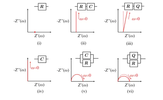
Normally, equivalent circuit model for a corrosion mechanism is pre-determined based on its Nyquist plot behavior. Basic evaluation of Nyquist plot using electrical elements is shown in Figure 2.5. R, C and Q represent resistor, capacitor and constant phase element, respectively according to these impedance equations;
where Y and n are the pre-factor and exponent of the constant phase element Q. Con-stant phase element Q is an element that behave in between resistor and capacitor (non-linear capacitor) [37]. Depending on the exponent n value, the corresponded Nyquist plot of a constant phase element tends to; 1) slightly deviate from vertical-line behavior of capacitor for series connection with a resistor (refer Figure 2.5(iii)) and 2) suppress the capacitor semi-circle behavior for parallel-connected to a resistor (shown in Figure
2.5(vi)).
There is also another element that has been widely used to describe charge accumulation process into porous carbon electrodes, called Warburg impedance [38]. The element is expressed similarly based on the constant phase element as in equation 5.2, but with exponent n value of 0.5. Corrosion mechanism have been practically modeled using the combination of these elements in various configuration (series and parallel connection) [39,40]. Z’(ω) -Z’’(ω) R Z’(ω) -Z’’(ω) C R ω=0 Z’(ω) -Z’’(ω) Q R ω=0
(i) (ii) (iii)
Z’(ω) -Z’’(ω) Z’(ω) -Z’’(ω) C C R ω=0 ω=0 Z’(ω) -Z’’(ω) Q R ω=0 (iv) (v) (vi)
Apparatuses and Experimental
Methods
This study is aimed to investigate the spraying method for zinc rich coating at room temperature using commercial zinc rich paints spray. The experimental work focuses on two main works. First, substrate treatment and spraying method. Second is material characterization and electrochemical properties investigation.
3.1
Substrate Pre-Treatment
In this study, a pure iron (Fe 99.5%) sheets are used as substrates for all coating sub-strates. The metallic sheet then cut into (10mm⇥20mm⇥0.5mm) in dimension. The metallic substrates are first serially polished with emery paper #600, #800, #1000 to produce mirror like surface. The metal substrates are then introduced into distilled wa-ter and rinsed using an utra sonic bath. Ethanol is employed to degrease the surface of the metal substrates and they rinsed again with distilled water. The cleaned substrates then, dried at room temperature before spraying process.
3.2
Spray Painting technique
After the substrate is properly cleaned and dried, it is then ready for the spraying process. In order to reduce the duration of spraying process, we employed ”wet on wet” spraying technique. In this technique, one coat is sprayed then the next coat immediately applied without and time left between coats. Spray that we employed are shown in Figure3.1. To achieved optimum and similar coatings, spraying process is conducted in temperature
ranges between 20 - 25 C. While spraying, the spray can is hold at a distance of 25-30 cm away from the metal surface and keep the hand moving to ensure the thin coats of paint will be deposited on the metallic substrate. After the spraying process the samples will be dried at ambient temperature for 1-2 hours. Schematic diagram of coated sample is shown in Figure 3.2.
3.3
Surface morphology and Composition by Scanning
Elec-tron Microscope (SEM)
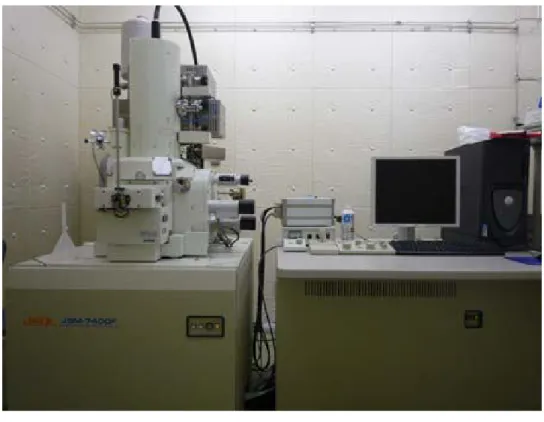
Morphology of the coated substrate was studied using Field Emission Scanning Electron Microscope (FE-SEM) JEOL JSM-7400F fitted with Energy Dispersive Analysis X-ray (EDAX) for chemical composition analysis of the coating. Actual setup as shown in Figure 3.3.
3.4
Electrochemical Polarization Curve Measurements
Corrosion behaviour of coated substrates at various coating thickness are studied using electrochemical polarisation curve measurements. In order to investigate the electro-chemical behaviour of the coated substrate polarization measurement was performed using electrochemical measurement system (Hokuto Denko HS-5000). The coated sub-strate sample is used as the working electrode. The sample is mounted on epoxy resin and exposed only the test surface. Then the sample is connected using copper wire. Plat-inum is employed as a counter electrode, and Ag/AgCl/KCl/KCl (saturated) is used as a reference electrode. Then, the reference electrode was connected to the test solution or electrolyte and secured using saturated KCl bridged. Polarization curve measurements of a sample are obtained in 0.5 and 1.0M NaCl solution from -1.0 V until 1.0V. The actual measurement setup and experimental diagram as shown in Figure 3.4 and 3.5below.
Coated area
(test surface)
Copper
wire
Epoxy
resin
Figure 3.3: The FE-SEM fitted with EDAX capability
3.5
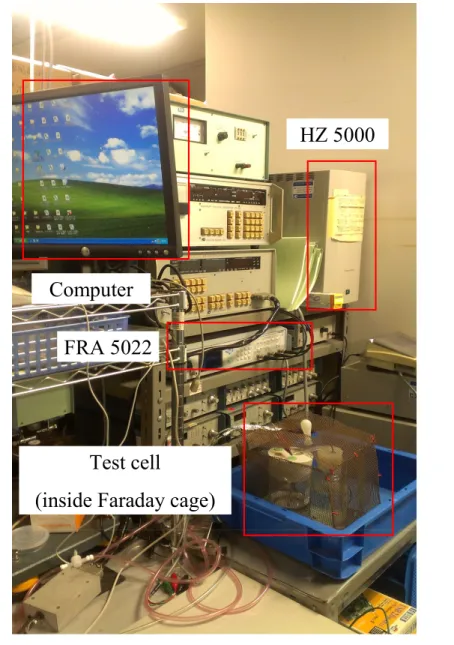
Electrochemical Impedance Spectroscopy
The electrochemical impedance of the coated metal substrates were characterized by electrochemical impedance spectroscopy measurement. The applied ac voltage ampli-tude is ±5mV with the frequency range between 10kHz and 10mHz. The measurement was carried out at the rest potential of the tested capacitors using the same electro-chemical measurement system (Hokuto Denko HZ 5000 and NF FRA5022) (refer Figure
Computer
HZ 5000
FRA 5022
Test cell
(inside Faraday cage)
Frequency response analyzer FRA5022 Computer Test cell Electrochemical system HZ5000 AC V I
Corrosion Performance of ZRPs
on mild steel in 0.5 NaCl solution
4.1
Background
Steel is one of the predominantly used metals. However, exposure to humidity and salin-ity in atmosphere will accelerate the corrosion protection of steel. Today, thousands of industrial manufacturers depend on paint or coating for long lasting strength, protection and improved productivity. Zinc is one of the most important elements for commercial application in the corrosion protection and improved productivity. Zinc coating displays its leadership and innovation on protecting the metal surfaces against corrosion and foul-ing usually caused by seawater. The protection of steel with epoxy based zinc rich paint is basically contributed by the sacrificial elements of paint, which is zinc that promotes cathodic protection to the metal substrate. Since late 1950s, the development of epoxy based zinc rich paint for corrosion resistance application has drawn much attention [29]. The main application area of ZRP is in the anti corrosion protection for industrial con-struction, for example pipelines, bridges, petrochemical or power industries, also for marine applications. Several studies have been carried out in order to elucidate the in-fluence of the zinc content on the electrochemical properties of these paints. Romagnoli et al. have reported that paint with Zn concentration larger than 60 wt.% is recom-mended in order to achieve a good protection towards corrosion [41]. Ji Hoon Park et al. has reported that with 60 wt.% of zinc in the paint, the performance of coating can be improved when the surface modified zinc particles were applied in the coating film [40]. Under immersion conditions, the time of cathodic protection depends on the zinc content in the coating film and they verified coatings with 60 volume percent of zinc powder showed good corrosion resistance mainly due to the cathodic protection. Since
then, the e↵ect of the surface morphology of zinc particle towards the coating film was reviewed significantly. The influence of chlorides, sulfates and nitrates on the steel/paint surface in terms of the underfilm corrosion was also investigated [42]. Vilche and Giudice et al. [20, 33, 43] studied the influence pigment shape and content of zinc primers by designing and manufacturing several series of coatings to obtained adequate pigment vol-ume concentration in order to enhance the anticorrosive performances. In atmospheric condition, the anticorrosive mechanism of zinc rich paint is dominated by the coating behavior of zinc corrosion products which inhibit further corrosion activity [44]. The in-fluence of the zinc content on the paint behavior has been studied, but most researchers show less concern to steel/paint interfacial structures which simulates practical applica-tion condiapplica-tions. This paper reports a study of the corrosion behaviors/performances of zinc rich paint (ZRP) applied on steel substrates under NaCl solution environment by using electrochemical measurements, scanning electronic microscopy (SEM) and energy dispersive X-ray spectroscopy (EDX).
4.2
Experimental
The cross section surface of specimens were polished and washed by ethanol prior to drying by using cold air and stored in a desicator to avoid corrosion at the paint or steel interface. A JEOL JSM-7400F SEM fitted with a source for energy dispersion X-ray analysis (EDX) was used to study the morphology and element distribution on the specimens cross-section area.
4.3
Results and Discussion
4.3.1 Adhesion test
Adhesion test were performed on ZRP coatings after the spraying process and immersion in 0.5 M NaCl solution to determine the efficiency of the coatings. By taking into account the results of cross-cut performed on ZRP coatings exposed to the salinity solution the appropriate failure mode can be determine and the lifetime of this kind of the binder can be understand. Cross-cut tests represented the additional criteria which were included in the failure time assessment presented in this work. The cross-cut area of the paint coatings and the stain marks left on the sticky tape after its removal were scanned and are shown in Figure4.1and Figure4.2. Detailed of the results from the cross-cut tests is shown in Table 4.1 and Table 4.2. This layer may susceptible to the loss of binding from its degradation, enabling accurate detection of changes in the efficiency of the coatings, i.e. the cohesion of coatings by performing standard cross-cut [45]. This test seems to non-sophisticated, the stains left on the sticky tape can be an indicator for loss cohesion between the coatings and the metal substrate. For example, coatings before exposed to the solution did not show any signs of removal of coatings regardless of thickness and zinc contents. However, after exposed in 0.5 M NaCl solution in 1 week, slightly some black stain can be observed on the sticky tape. This showed that the paints established relatively highly air tight coatings, which completely inhibited the oxidation of the metal substrate.
Table 4.1: Adhesion properties of ZRP coatings after spraying process (Initial state)
Samples 1 layer 3 layers 5 layers
74% 10/10 10/10 10/10
96% 10/10 10/10 10/10
Figure 4.1: Cross-cut test after spraying process (Initial state). The stain left on the sticky tape after the cross-cut test is shown on the hand left side
Figure 4.2: Cross-cut test after immersion in 0.5 M NaCl for 1 week. The stain left on the sticky tape after the cross-cut test is shown on the hand left side
4.3.2 Cross-section morphologies
Figure 4.3 depicted a specimen with one layer of ZRP coating including distribution of Zn, Fe and C, respectively. As shown in Figure 4.3 (a), the Zn layer was compact and spherical in structure with thickness ca. 10-18µm. From the observation, it can
Table 4.2: Adhesion properties of ZRP coatings after immersion in 0.5 M NaCl solu-tion for a week
Samples 1 layer 3 layers 5 layers
74% 8/10 8/10 8/10
96% 7/10 7/10 7/10
Zn 10μm C 10μm Metal substrate ZRP (a) 10μm Metal substrate Fe 10μm
Figure 4.3: Cross-section of SEM micrograph of 1 layer coating and distribution of Zn, Fe and C at initial stage
be noted, the layer of the spray is constant and the distribution of zinc particles is homogeneous. Also from this observation, the boundary between metal substrate and ZRP is clear. EDX maps of cross sections for (a) was performed to determine the element distribution. A large amount of Zn was detected at the paint/steel interface and scattered on metal substrate and ZRP is clear.
Figure 4.4 shows the cross-sectioned of 1 layer coating (a) and 5 layers coating (b) at initial stage. For (a), its thickness was about 10-18 µm. Obviously, the zinc layer was compact and homogeneous. In contrast, for (b) the zinc particles along the metal interface was compact but porous and loose at the paint surface.
4.4
Open Circuit Measurements
The evolution of the free corrosion potential Ecorr allows to follow the electrochemical
Metal substrate
ZRP
Epoxy
5μm
(a) Cross-section of 1 layer coating specimen
Metal substrate
ZRP
5μm
(b) Cross-section of 5 layer coating specimen
Zn⌦ Zn2++ 2e (4.1)
O2+ 2H2O + 4e ⌦ 4OH (4.2)
According to Abreu et al. [17] the Ecorr evolution is in close relationship with the
varia-tion of the ratio of active areas which is between zinc and metallic substrate (zinc/metal). In other words, the increase in the potential correlates to the decrease of the electroac-tive zinc area which means the decrease of the cathodic protection. This is commonly, Zinc rich paints can protect the steel cathodically when zinc particles in the coatings have electric connection to steel substrate. Figure 4.5 shows variation in corrosion po-tential with time for samples coated with 74wt% ZRP exposed in 0.5 M NaCl solution. The potential increased to about -0.64V and tend to maintain, which means that the steel was corroding approaching the end. Probably the zinc concentration was low that zinc particles were consumed and the steel started to corrode or we may say that there is no electrical contact and thus there is no protection of the substrate. According to visual observation after the test, particularly for sample coated with 1 and 3 layers of coating covered with white zinc corrosion products more than 5 layers coating sample. Thus, these results suggest that the numbers of coating do improve the anticorrosive performance.
On the other hand, there were large di↵erences in the performances of 96 wt.% ZRP as shown in Figure4.6. The potential of zinc in sodium chloride is approximately -1.05 V, while the steel substrate approximately -0.65 V. This shows that the zinc particles in the paint were galvanic connection to the steel substrate. The potential increased during the test period from -1.0 V in the beginning to -0.55 V in the end. This result exhibit that the zinc particles were consumed or that galvanic contact was lost with the time. It is interesting to note that the potential for 96 wt.% ZRP coated samples were close to that of zinc and exhibited hardly any di↵erences in appearances. The potential of the sample increases when the amount of zinc particles in the coating layer with the steel decreases. The galvanic may be lost due to corrosion of the zinc particles, either by total depletion of the particles or formation of isolating corrosion products between particles and the steel substrate.
0 20 40 60 -0.72 -0.64 -0.56 -0.48 -0.40 Op en c ir cu it p ot en ti al ( Vs sc ) Time (days) 1 layer 3 layers 5 layers
Figure 4.5: Variations in corrosion potential with time for samples coated with 74wt.% ZRP exposed in 0.5 M NaCl solution at ambient temperature.
coatings were increased, the anode current shifted to lower current density compared to one layer coating, which indicates that numbers of coatings have significant e↵ect on anodic current.
Figure 4.8shows the polarization curves of 74 wt.% ZRP coated samples in 0.5M NaCl solution. There is a cathodic oxidation peak at -0.85V which attributes to the zinc potential. It is found that polarization curves have the similar trends with 96 wt.% ZRP coated samples. They are characterized by corrosion potential shifted to less noble potential as numbers of coatings are increased. This also implied that zinc particles inside the coating and steel substrates are properly contact. On the other hand, the current density become lower as numbers of coating increased. This may be explained, as numbers of coating increased epoxy thickness also increased which formed a barrier coat. Therefore, the process of corrosion may be inhibited.
4.5
Current density inhibition model
0 20 40 60 -1.0 -0.9 -0.8 -0.7 -0.6 -0.5 Op en c ir cu it p ot en ti al ( V ss c) Time (days) 1 layer 3 layers 5 layers
Figure 4.6: Variations in corrosion potential with time for samples coated with 96 wt.% ZRP exposed in 0.5 M NaCl solution at ambient temperature.
sample with 1 layer, the zinc particles are deposited homogeneously. As we apply the paint continuously without letting the first layers to be dry enough. Therefore, when we apply the second and the next layer, the tendency for the zinc particles to settle down and left the epoxy to the surface are high due to the atomic weight of zinc is higher than epoxy. The zinc particles will be beneath the top layer of epoxy. When the epoxy layer became thicker it will act as barrier, thus, the current density become lower too. As a whole, the protection performance of ZRP coatings may be though depend on the barrier e↵ect of epoxy layers and the sacrificial e↵ect of zinc. In reality, it may well rely on producing the maximum resistance properties of zinc layers as outlined previously. Commonly, epoxy layer with high thickness have lower porosity, but microcracks may occur due to the stronger tensile stress existed in thicker epoxy layers. However, this attributed to the improvement corrosion performance provided by epoxy layer.
4.6
Chapter Conclusion
10μm -1.0 -0.8 -0.6 -0.4 10-5 10-4 10-3 10-2 10-1 1 10 102 103 Pure Fe metal Pure Zn metal Zn 1 layer coating Zn 3 layer coatings Zn 5 layer coatings C ur re nt de ns it y, i / mA ·cm -2
Potential, E / V vs. Ag/AgCl/KCl sat.
Figure 4.7: Polarization measurement result for pure iron, zinc and coated samples in 0.5M NaCl solution
-1.2 -0.8 -0.4 0.0 0.4 10-9 10-8 10-7 10-6 10-5 10-4 10-3 10-2 10-1 1 Zn 1layer coating Zn 3layer coatings Zn 5layer coatings Cu rr en t de n si ty , i /mA. cm -2
Potential, E/V vs. Ag/AgCl/KCL sat.
Metallic substrate
1 layer coating
specimen
Zinc
layer
Epoxy
level
3 layers coating
specimen
5 layers coating
specimen
Metallic substrate
Metallic substrate
Comparison of corrosion
resistance in di↵erent
concentration solution
5.1
Overview
Usage of metallic materials in process industries is inevitable. Corrosion has become a major problem especially in gas and oil industries. Corrosion in metal pipes, valves and other parts of constructions has caused so many losses to the industries. According to US Federal Highway Administration (FHWA) and National Association of Corrosion Engineers (NACE) on study of corrosion costs and preventive strategies in United States claimed that the total annual estimated direct cost of corrosion in US approximately around 276 billion US dollar equivalent to 3.1% nation gross domestic products (GDP) [46]. Therefore, the study of corrosion is relevance and important in order to eliminate this kind of loss. Exposure to humidity and salinity in the atmosphere will accelerate the corrosion of steel. Today, thousands of industrial manufacturers depend on paint or coating for long lasting strength, protection and improved productivity. Many coatings have been used to attain that purpose, some of them, however, show less satisfactorily than expected. Zinc is one of the most important components for commercial applica-tion in the corrosion protecapplica-tion and improved productivity. Zinc has been depicted to be more e↵ective than other coating types. The protection of steel with epoxy based zinc rich paint is based on the general principle of cathodic protection by metallic zinc in contact with ferrous substrate. The positive e↵ects of epoxy based zinc rich paint (ZRP) and on metal substrate towards corrosion resistance of paints have drawn much atten-tion since late 1950s [1]. In the film of ZRP, the particles of pigments are close contact
5.2
Experimental
5.2.1 Materials and experimental set-up
All chemicals were reagent grade and used as received without purification. Distilled wa-ter was employed in order to prepare the solutions. The electrochemical measurements were carried out by using the conventional three electrode setup. The cell was connected to 5000 Autolab potentiostat. Test specimens were pure iron 99.5% (10mm⇥20mm ⇥ 0.5mm), abraded with #600, #800 and #1000 emery papers. In order to ensure the absence of dust, oil and foreign matters, specimens were cleansed with ethanol using the ultrasonic bath. Commercial zinc 74% and 96% (Atom Paint Co. Ltd., Japan) content epoxy-ZRP was applied onto specimen by air spraying following the manufacturers in-structions. The specimens were coated with 1, 3 and 5 layers respectively. After the coatings had been applied, the specimens were allowed to cure at ambient temperature.
5.2.2 Characterization of ZRP coating
Table 5.1: Average of coating thickness after spraying process
Number of coating Coating thickness (µm)
1 30-35
3 40-45
5 65-70
5.3
Results and Discussion
In previous chapter, Figure4.4shows SEM images that show that the Zn coated homo-geneously the surface of the metallic substrate after the spraying process. The average diameter of the zinc particles was about 3-5µm. Average thickness for 1, 3 and 5 layer coating is shown in Table5.3
The cross-section micrographs show the zinc rich paints based on epoxy with coating layer 1, 3 and 5 respectively on metal substrate. From Figures 5.1 and 5.2it seen that zinc particles are closely packed on the metallic substrate surface and porous toward the coating surface.
5.3.1 E↵ect of concentration in NaCl solution
The polarization measurement was carried out for coated metallic substrates in 0.5 and 1.0 M NaCl solution at scan rate of 1.0 mVs 1 at room temperature. It is obvious from
Figure5.3show that the corrosion potential for all coated samples is more positive than that marked in the case of 96% in 0.5 M NaCl solution. It is observed that, the corrosion current density, Icorr, values of ZRP coating
The polarization measurement was carried out for coated metallic substrate in 0.5 M NaCl solution at a scan rate of 1.0mVs 1 at 25. It is obvious from Figure 5.3 show that the corrosion potential for all coated samples is more positive than that marked in the case of 96%-5. It is observed that, the corrosion current density, Icorr, values of
ZRP coatings gradually decrease as the coating thickness increase up to 5 layers and the 96%ZRP-5 has the lowest value of Icorr (0.0218µA/cm2). Also the most negative
value of Ecorr (-742mV versus Ag/AgCl/KCl) signifies that 96%ZRP-5 sample act as
sacrificial coating and has the lowest tendency to corrode. However, in contrast samples coated with 74%-ZRP exhibit less definite shift in Ecorr (-463 to -502mV versus
Ag/Ag-Cl/KCl) and Icorr(6.13µA/cm2to 6.72µA/cm2) which implied that samples coated with
10μm (a) 74%-1 10μm (b) 74%-3 10μm (c) 74%-5
10μm (a) 96%-1 10μm (b) 96%-3 10μm (c) 96%-5
While for samples measured in 1.0M NaCl solution, samples coated with 96% Using Stern-Geary equation 5.2 [25, 48, 49] the polarization resistance (Rp) was determined
from the Tafel plots:
-1.0 -0.5 0.0 0.5 1.0 1E-9 1E-8 1E-7 1E-6 1E-5 1E-4 1E-3 0.01 0.1 96%-1 96%-3 96%-5 74%-1 74%-3 74%-5 C u rr en t de nsi ty , i / mA ·cm -2
Potential, E / V vs. Ag/AgCl/KCl sat.
(a) 0.5 M NaCl solution
-1.0 -0.5 0.0 0.5 1.0 1E-9 1E-8 1E-7 1E-6 1E-5 1E-4 1E-3 0.01 0.1 1 96%-1 96%-3 96%-5 74%-1 74%-3 74%-5 C ur re nt d en si ty , i / m A ·cm -2
Potential, E / V vs. Ag/AgCl/KCl sat.
(b) 1.0 M NaCl solution
0 40 80 120 160 200 240 -1.1 -1.0 -0.9 -0.8 -0.7 -0.6 -0.5 74%-1 74%-3 74%-5 (b) Po te nt ia l, E / V v s. A g/A gC l/K C l s at . Time, t/h (a) 74%-ZRP
Figure 5.4: Evolution of the free corrosion Ecorr with immersion time for 74%-ZRP
coated samples
Rp = a c
2.3031 Icorr ( a+ c)
(5.1)
Where Icorr, a and c are the corrosion density, anodic Tafel slope and cathodic Tafel
slope respectively. We also calculate the corrosion rate (Vcorr in millimetre per year)
by using the following equation 5.2 [25,49]. Where Icorr, M.W, n and d are corrosion
current density (µA/cm2), molar mass (g/mole), charge number and density (g/cm3) of tested metal, respectively.
Vcorr =
0.0032⇥ Icorr⇥ (M.W )
n⇥ d (5.2)
The samples coated with 96%-5 have the most negative Ecorr value with respect to the
zinc contents. For instance, the 74%ZRP-5 shows a corrosion potential of -0.45V versus Ag/AgCl/KCl which indicates that the 74%ZRP-5 is noble toward the electrochemi-cal corrosion with good barrier e↵ect instead of galvanic protection compared to the 96%-ZRP coated sample with Ecorr value of -0.76V versus Ag/AgC/KCll. The
electro-chemical parameters from Tafel plots (anodic Tafel slope ( a), cathodic Tafel slope ( b),