歯車測定機の精度向上に関する研究
田口 哲也
電気通信大学大学院電気通信学研究科 博士(工学)の学位申請論文
2012 年 3 月
歯車測定機の精度向上に関する研究
博士論文審査委員会
主査 明 愛国 准教授
委員 石川 晴雄 教授
委員 下条 誠 教授
委員 青山 尚之 教授
委員 金森 哉吏 准教授
著作権所有者
田口 哲也
2012
Development of High Precision Gear Measuring Machine
Tetsuya Taguchi
Abstract
The high precision gears are strongly required for advanced motion and power transmission. And the improved evaluation technology for the precision gears is becoming indispensable. Moreover, the reliability of the measured value became important when the accuracy of the gear becomes high, and the establishment of the traceability system has been needed. For the establishment of the traceability system, the higher precision gear measuring machine (GMM) with a smaller measurement uncertainty than the conventional GMM is expected to contribute to improve gear calibration uncertainty.
First, some problems of the prototype GMM were clarified from the evaluation result, the error factor by a geometric model was analyzed and the measurement accuracy was improved by upgrading the prototype GMM. Next, in order to improve the response characteristics of drive mechanism which is one of the major factors of the measurement deviation in the prototype GMM, the new concept using direct drive mechanism was proposed, the experimental device specialized for tooth profile measurement was developed, and higher response characteristics and tooth profile measurement accuracy than the prototype GMM were achieved after improving the control performance. Moreover, the high precision GMM which adopted calibration of the machine accuracy of each drive system, compensation of the displacement measurement accuracy of a detector, etc. was developed, and the high repeatability and reproducibility of profile and helix measurement were verified by the evaluation method using the standard deviation.
Therefore, the high precision GMM was verified having sufficient measurement capability to evaluate the artifacts and can be applied to the gear calibration system.
歯車測定機の精度向上に関する研究 田口 哲也
概 要
歯車の幾何学的形状・寸法については,形状誤差の大小によって歯車精度を 等級分けする歯車精度規格があり,その測定には様々なタイプの歯車測定機が 利用されている.しかし,歯車測定機の測定値を保証するシステムが整備され ていないため,特に高精度が要求される歯車の精度等級(測定値)の信頼性が 保証されず,国際的な取引や分業体制の進展を妨げている.そこで歯車の精度 を保証するために,国際的に認められたトレーサビリティ体系に基づく歯車測 定機のキャリブレーション方法を標準化する研究が進められている.その中に おいて,トレーサビリティ体系を確立するためには,より不確かさが小さく,
一般に使用される歯車測定機を校正する基準器を評価できる高精度な測定機
(歯車測定基準機)が必要となり,(社)日本歯車工業会を中心とした研究開発 プロジェクトでは,高精度歯車測定機(以下,試作機)を試作し,従来の歯車 測定機より高い測定精度が確認された.しかし,被測定歯車の取り付け位相や 測定速度が変わると測定結果である歯形誤差曲線が僅かながら変化するという 問題点が明らかになり,精度を十分に保証できるまでには至らなかった.
そこで,まず試作機の幾何学的モデルによる誤差要因の解明と実機改良によ る精度向上を試み,被測定歯車の取り付け位相の影響については,その要因と して取り付けの偏心もあるが,測定機内部のロータリエンコーダの偏心が大き な要因であることを示した.また,特に顕著に現れていた測定速度の影響につ いては,高速データ読み取り装置を構築して測定したデータを解析し,その原 因がエイリアシングであることを明らかにした.エイリアシングとは,サンプ リング周期が測定対象の周期の 1/2 より大きいときに,測定できない高次成分 が低次成分として測定値に現れる現象であり,サンプリング周期が変化すると 低次成分にも変化が現れる.高速サンプリングと移動平均フィルタによってエ イリアシングの影響を低減し,測定の繰り返しばらつきは小さくなったが,測 定データをフーリエ解析した結果,高次成分は試作機の機構に起因しているこ
次に,試作機における測定の繰り返しばらつきを改善するために,測定デー タの高次成分の要因の一つである機構を検討し,ウォームギヤやボールねじ等 を用いない直接駆動方式の新しい測定機構を提案した.その有効性を検証する ために,歯形測定に特化した実験機として開発した回転駆動系と直線駆動系の 機構および制御方式について述べる.回転駆動系はエアベアリングを採用して DD(ダイレクトドライブ)モータによって直接駆動する機構とし,直線駆動系 はエアスライドを採用してリニアモータによって直接駆動する機構とした.各 駆動系共に,直接駆動方式に適したサーボ制御を行うために、制御系シミュレ ーションと駆動実験によって位置制御系とトルク制御系を比較・検討し,高い 応答性を発揮する制御則を決定した.そして,実際の歯形測定において測定の 繰り返しばらつきが試作機より小さくなることを確認した.
更に,実験機から得られた直接駆動方式測定機構の知見に加えて,精度の安 定化や高精度化のための方策を適用して開発した高精度歯車測定機(以下,開 発機)について述べる.回転駆動系は実験機と同様の機構とし,その回転角度 の計測には自己校正型ロータリエンコーダを採用して偏心等に起因する角度誤 差を低減させた.直線駆動系は実験機の機構に加えて歯すじ測定に必要な垂直 軸を直接駆動機構として組み込み,歯形・歯すじ測定に対応できるY-Zステー ジとした.また,測定機の基準となる本体ベッドには花崗岩を採用し,伝統の キサゲ技術を駆使して高い機械精度を実現した.更に,開発機での測定値の不 確かさを小さくするために,測定子のたわみを補正する高精度な変位検出シス テムや直線駆動系の真直度を校正する方法を開発した.そして,開発機の性能 評価では,測定の繰り返し性と再現性の評価およびインボリュートアーティフ ァクトの校正値との比較を行い,高い測定能力が確認できた.
そして,日本における歯車のトレーサビリティ体系を確立するために重要な 歯車校正の現状について述べ,その中での開発機の位置付けについて述べる.
歯車校正システムへの適用評価の指標として,開発機の最高測定能力を JCSS 歯車校正機関における不確かさ算出要領に準じて評価し,現在の歯車測定基準 機の最高測定能力を上回ったことが確認できた.よって,開発機は歯車校正シ ステムに組み込むのに十分な測定能力を持つことが検証できた.
最後に,本研究で得られた成果をまとめ,今後の課題と展望について述べる.
目次
第1章 序 論... 1
1.1 研究背景... 1
1.1.1歯車の測定原理... 2
1.1.2歯車測定機の研究開発... 8
1.1.3標準化... 11
1.2 本研究の目的... 14
1.3 本論文の構成... 15
第2章 既存の高精度歯車測定機の評価... 16
2.1 開発経緯... 16
2.2 システム構成... 17
2.3 測定精度の評価... 19
2.3.1評価方法... 19
2.3.2評価結果... 21
2.4 問題点の解析... 26
2.4.1測定機における測定誤差の原因検討... 26
2.4.2誤差モデルによる測定誤差の原因検討... 33
2.5 実験による検証... 43
2.5.1測定速度の影響に関する実験... 43
2.5.2取り付け位相の影響に関する実験... 54
2.6 まとめ... 58
第3章 直接駆動方式実験機の開発... 59
3.1 はじめに... 59
3.2 基本方針... 61
3.3 システム構成... 64
3.3.1回転軸の機構... 65
3.3.2直動軸の機構... 70
3.3.3制御・計測システム... 75
3.4 回転軸の制御... 80
3.4.1位置指令制御系の検討... 80
3.4.2トルク指令制御系の検討... 82
3.4.3制御系の改良... 90
3.5 直動軸の制御... 93
3.5.1位置指令制御系の検討... 93
3.5.2トルク指令制御系の検討... 95
3.5.3制御系の改良... 104
3.6 二軸駆動性能の検証... 109
3.6.1回転軸への追従制御による検証... 109
3.6.2軸毎の制御による検証... 111
3.7 測定精度の評価... 113
3.7.1歯形測定と結果... 113
3.7.2評価用フィルタの設計... 118
3.7.3繰り返し性の評価... 121
3.8 測定精度向上の検討... 122
3.8.1レーザ測長機の測定値補正... 122
3.8.2測定力一定制御... 124
3.8.3測定データのフィルタ処理... 129
3.9 まとめ... 131
第4章 新高精度歯車測定機の開発... 132
4.1 はじめに... 132
4.2 基本方針... 133
4.3 システム構成... 134
4.3.1機構の開発... 135
4.3.2検出器の開発... 139
4.3.3測定精度安定化のための工夫... 142
4.3.4制御・計測システム... 143
4.4 測定機の校正および補正... 144
4.4.1空間誤差の校正... 144
4.4.2測定機の温度補正... 151
4.5 駆動系の性能評価... 157
4.5.1回転駆動系の評価... 157
4.5.2直線駆動系の評価... 158
4.6 測定精度の評価... 162
4.6.1繰り返し性の評価... 162
4.6.2再現性の評価... 166
4.6.3歯形測定精度の評価... 168
4.7 まとめ... 170
第5章 歯車校正システムへの適用評価... 171
5.1 はじめに... 171
5.2 歯車校正の現状... 172
5.2.1歯車校正機関... 172
5.2.2歯車測定基準機... 173
5.3 新高精度歯車測定機の適用評価... 175
5.3.1測定機の各軸の精度測定... 175
5.3.2最高測定能力の算出... 179
5.4 まとめ... 188
第6章 結 論... 189
6.1 本研究で得られた成果... 189
6.2 今後の課題と展望... 193
参考文献... 195
謝 辞... 201
図目次
1.1 Photograph of an example of GMM... 1
1.2 Basic principle of involute profile measurement... 2
1.3 Total profile deviation ... 3
1.4 Profile slope deviation... 4
1.5 Profile form deviation ... 4
1.6 Basic principle of helix measurement ... 5
1.7 Total helix deviation ... 6
1.8 Helix slope deviation... 6
1.9 Helix form deviation ... 6
1.10 Pitch deviations: ISO 1328-1 [8]... 7
1.11 Schematic drawing of involute testing instrument with a base circle disc 8 1.12 Photograph of an involute testing instrument at PTB... 9
1.13 Schematic drawing of a digitized profile measurement [10]... 10
1.14 Schematic drawing of an digitized experimental instrument [11] ... 10
1.15 Schematic drawing of the CMM with laser tracer... 11
1.16 Hierarchy of Gear calibration... 12
2.1 Photograph of the prototype GMM ... 16
2.2 Composition of prototype GMM... 18
2.3 Measuring method of tooth profile... 18
2.4 Artifacts for verification of GMM... 19
2.5 Schematic drawing of standard deviation calculation ... 20
2.6 Photograph of involute artifact: JGMA988Master ... 21
2.7 Results of ten measurements for about ten minutes ... 22
2.8 Histogram of deviation from average curve ... 23
2.9 Change of profile deviation by different measurment speed... 23
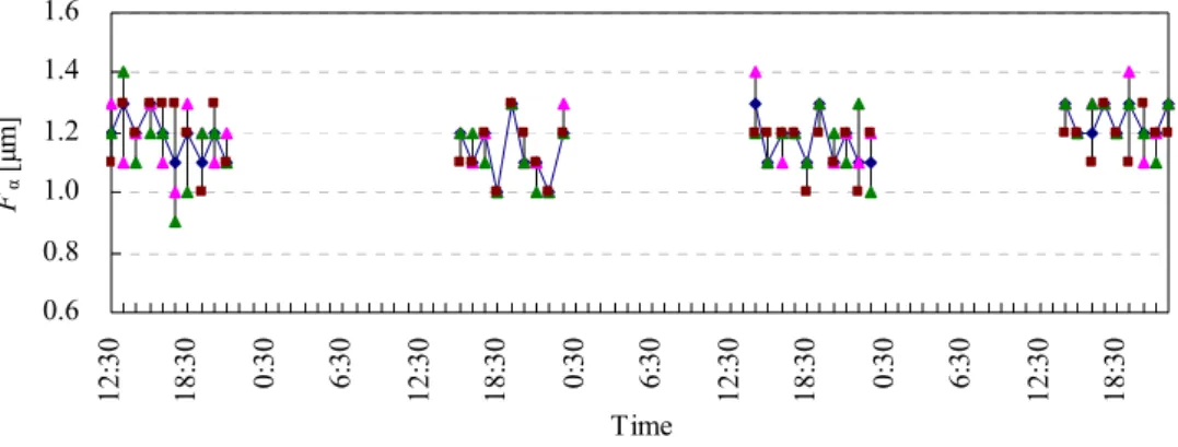
2.10 Transition of total profile deviation in four days... 24
2.11 Transition of profile slope deviation in four days... 24
2.12 Results of artifact setting on different phase ... 25
2.13 Aliasing accompanying the sampling of a sine wave [47] ... 31
2.14 Aliasing and Nyquist frequency by discrete data reading [47]... 31
2.15 Cylindrical coupling for driving work... 32
2.16 Coodinate system of GMM ... 33
2.17 Error model of tangent direction ... 34
2.18 Error model of radial direction ... 36
2.19 Error model with eccentricity and incline ... 37
2.20 Error simulation of base radius by gap 10[μm] of centers ... 38
2.21 Error model of center eccentricity between rotation and rotary encoder 39 2.22 Error simulation of center eccentricity ... 40
2.23 Error model of center eccentricity between rotation and involute origin 40 2.24 Error simulation of involute profile measurement with eccentricity... 41
2.25 Error model of base diameter ... 42
2.26 System configuration of GMM add on FSD... 44
2.27 Comparison of profile deviations sampling by GMM and FSD... 46
2.28 Profile deviations by changing sampling interval of FSD... 47
2.29 Profile deviation in the sampling interval T=1.0[ms] (v=0.1[mm/s]) ... 48
2.30 Fourier analysis of profile deviation in T=1.0[ms] (v=0.1[mm/s]) ... 48
2.31 Profile deviation in the sampling interval T=1.5[ms] (v=0.1[mm/s]) ... 48
2.32 Fourier analysis of profile deviation in T=1.5[ms] (v=0.1[mm/s]) ... 49
2.33 Profile deviation in the sampling interval T=1.0[ms] (v=0.2[mm/s]) ... 50
2.34 Fourier analysis of profile deviation in T=1.0[ms] (v=0.2[mm/s]) ... 51
2.35 Profile deviation in 1/10 angular step (v=0.1[mm/s], T=1.0[ms])... 51
2.36 Fourier analysis in 1/10 angular step (v=0.1[mm/s],T=1.0[ms])... 52
2.37 Comparison of profile deviation by different moving average point ... 53
2.38 Measurment method of eccentricity of artifact... 54
2.39 Measurement result of eccentricity by setting artifact... 56
2.40 Profile deviations simulated eccentricity by setting artifact... 57
2.41 Comparison of influence of eccentricity by setting artifact... 57
3.1 Deviations of profile measurement by the conventional GMM ... 60
3.2 Control command curve ... 62
3.3 Composition of the experimental instrument ... 64
3.4 Mechanism improvement of rotary axis... 65
3.5 Photograph of rotary axis ... 69
3.6 Mechanism improvement of linear axis ... 70
3.7 Schematic drawing of ball joint machanism... 71
3.8 Photograph of linear axis... 74
3.9 Photograph of the experimental instrument... 74
3.10 Control and measurement system... 75
3.12 Block diagram of position command control system ... 78
3.13 Control block diagram of servo driver ... 78
3.14 Block diagram of torque command control system... 79
3.15 Settling accuracy of rotary axis ... 81
3.16 Response characteristic of rotary axis ... 81
3.17 Block diagram of PID control for the rotary axis... 82
3.18 Settling accuracy of rotary axis ... 83
3.19 Response characteristic of rotary axis ... 84
3.20 Block diagram of PID+FF control for the rotary axis ... 85
3.21 Schematic drawing of identification experiment... 85
3.22 Measurement result of coulomb friction torque ... 86
3.23 Measurement result of viscosity torque... 87
3.24 Response characteristic of rotary axis ... 87
3.25 Difference of two types of velocity command curve (Accelration part) . 89 3.26 Response characteristic of rotary axis ... 89
3.27 FFT analysis on the deviation of rotary axis ... 90
3.28 Block diagram of the rotary axis ... 91
3.29 Response characteristic of rotary axis ... 92
3.30 Settling accuracy of linear axis... 94
3.31 Response characteristic of linear axis... 94
3.32 Block diagram of PID control for the linear axis ... 95
3.33 Settling accuracy of linear axis... 96
3.34 Response characteristic of linear axis... 97
3.35 Theory of friction coefficient μ... 98
3.36 Theory of viscosity coefficient λ and inertia coefficient κ... 99
3.37 Measurement result of μ... 100
3.38 Measurement result of λ and κ... 100
3.39 Schematic diagram of motor constant ... 100
3.40 Schematic drawing of measurement method for motor constant ... 101
3.41 Measurement result of motor constant ... 101
3.42 Block diagram of PID+FF control for the linear axis... 102
3.43 Response characteristic of linear axis... 103
3.44 Performance improvement of the linear axis... 105
3.45 Schematic drawing of linear motor ... 106
3.46 Location of the linear encoder... 106
3.47 Block diagram of the linear axis... 106
3.48 Response characteristic of linear axis... 107
3.49 Fourier analysis of the deviation of linear axis ... 108
3.50 Block diagram for synchronous control ... 109
3.51 Synchronous deviation of follow-up control ... 110
3.52 Block diagram for synchronous control ... 111
3.53 Synchronous deviation of independent control ... 112
3.54 Measurement results at speed 10[mm/s] ... 114
3.55 Measurement results at speed 5[mm/s] ... 115
3.56 Measurement results at speed 1[mm/s] ... 116
3.57 Detection range of detector ... 117
3.58 Profile deviation (Left) and Fourier analysis (Rignt) at 10[mm/s]... 119
3.59 Profile deviation (Left) and Fourier analysis (Rignt) at 5[mm/s]... 119
3.60 Profile deviation (Left) and Fourier analysis (Rignt) at 1[mm/s]... 119
3.61 Profile deviation (Left) and Fourier analysis (Rignt) at 10[mm/s]... 120
3.62 Profile deviation (Left) and Fourier analysis (Rignt) at 5[mm/s]... 120
3.63 Profile deviation (Left) and Fourier analysis (Rignt) at 1[mm/s]... 120
3.64 Measurement results repeated 10 times at 10[mm/s] ... 121
3.65 Environment measuring system for laser measurement ... 122
3.66 Amplifier circuit of environment measurement ... 123
3.67 Comparison of profile deviation for two different compensation ... 123
3.68 Photograph of geometrical artifacts... 125
3.69 Form deviation δp between involute profile and circle (ε>0) ... 125
3.70 Deflection of stylus ... 127
3.71 Control law adopted geometry compensation ... 127
3.72 Measurement and analysis results of Pin Master... 128
3.73 Filtering of profile deviation ... 130
3.74 Filtering of helix deviation ... 130
4.1 Composition of high precision GMM ... 134
4.2 Design of rotary axes... 135
4.3 Self-calibratable rotary encoder ... 136
4.4 Calibration results by the angle self-calibration system... 137
4.5 Design of linear axes ... 138
4.6 Composition and verification of detector ... 139
4.7 Example of three kinds of styli... 140
4.8 Deflection of three kinds of styli ... 141
4.10 Control and measurement system of developed GMM ... 143
4.11 Photograph of detector... 144
4.12 Check master HMC-300H (L=300mm) by MITUTOYO... 145
4.13 Calibration of Y axis by using check master ... 145
4.14 Measurement result by using check master... 146
4.15 Comparison of calibration and Laser measurement ... 146
4.16 Test bar CL-EA46 (φ30×L255) ... 147
4.17 Photograph of calibration by measuring a test bar ... 147
4.18 Procedure for the calibration by measuring a test bar ... 148
4.19 Calibration curve calculated from measured data ... 148
4.20 Check master HMC-600H (L=600mm) by MITUTOYO... 149
4.21 Calibration of Z axis by using check master ... 150
4.22 Calibration curve calculated by measured data ... 150
4.23 Calibration curve calculated by measured data ... 150
4.24 Specification of temperature sensor (Type K thermocouple) ... 151
4.25 Appearance attached with temperature sensors... 152
4.26 Front and side view of developed GMM... 153
4.27 Schematic drawing of measuring the center of a test bar ... 153
4.28 Temperature alteration of developed GMM ... 154
4.29 Alignment transition of center column... 155
4.30 Correlation of alignment and temperature... 155
4.31 Transition comparison of alignment and temperature ... 156
4.32 Correlation of center coodinates and temperature ... 156
4.33 Appearance of rotary axis (C axis) ... 157
4.34 Settling accuracy of rotary axis ... 158
4.35 Response characteristics of rotary axis... 158
4.36 Appearance of linear axes (X axis and Y-Z stage)... 159
4.37 Settling accuracy of linear axes... 160
4.38 Response characteristics of linear axes ... 161
4.39 Photograph of involute artifact and measurement appearance ... 162
4.40 Repeatability of profile measurement with helix angle 0° ... 163
4.41 Photograph of helix artifact and measurement appearance ... 164
4.42 Repeatability of helix measurement with helix angle 0° ... 165
4.43 Reproducibility of tooth profile measurement with helix angle 0° ... 167
4.44 Reproducibility of helix measurement with helix angle 0° ... 167
4.45 Photograph of a primary master ... 168
4.46 Comparison of tooth profile ... 169
5.1 Traceability of gear calibration to the national standard ... 172
5.2 Positioning of GMMs ... 173
5.3 Definition of GMM’s axes... 175
5.4 Definition of GMM’s axes... 178
表目次
1.1 An example of gear accuracy grade... 14
2.1 Major specifications of developed GMM ... 17
2.2 Major dimension of involute and helix artifacts... 19
2.3 Dimensions of involute artifact: JGMA988Master... 21
2.4 Repeatability for about ten minutes ... 22
2.5 Repeatability for about ten minutes ... 24
2.6 Influence of artifact setting on different phase ... 25
2.7 Specifications of the air slide ... 26
2.8 Specifications of the air bearing... 27
2.9 Composition of drive system ... 27
2.10 Specifications of the rotary encoder ... 28
2.11 Errors by eccentricity and incline ... 38
2.12 Major specifications of FSD ... 43
2.13 Facters gussed from specification of GMM... 50
2.14 Difference of width by data number for average ... 53
3.1 Major specifications of a prototype instrument... 61
3.2 Specifications of the target gears... 61
3.3 Conditions of measurement speed... 63
3.4 Comparison of rotary axis components ... 65
3.5 Specifications of the shaft ... 66
3.6 Specifications of the air bearing ... 66
3.7 Specifications of the rotary encoder ... 67
3.8 Inertia of moving parts ... 67
3.9 Parameters for DD motor selection ... 68
3.10 Specifications of the DD motor... 68
3.11 Assembly accuracy of rotary axis... 69
3.12 Comparison of linear axis component ... 70
3.13 Specifications of the air slide ... 71
3.14 Specifications of the linear encoder ... 72
3.15 Weight of moving parts ... 73
3.16 Parameters for linear motor selection... 73
3.17 Specifications of the linear motor... 73
3.18 Assembly accuracy of linear axis ... 74
3.19 Components of control and measurement equipment ... 76
3.20 Specifications of servo driver... 77
3.21 Parameters for servo control... 80
3.22 Parameters for servo control... 83
3.23 Calculation result of coulomb friction torque... 86
3.24 Calculation result of viscosity coefficient ... 87
3.25 Parameters for servo control... 92
3.26 Parameters for servo control... 93
3.27 Parameters for servo control... 96
3.28 Calculation results of each coefficient... 99
3.29 Motor constant of linear motor... 102
3.30 Parameters for servo control... 108
3.31 Measurement condition ... 113
3.32 Measurement results for each measurement speed... 113
3.33 Number of moving average for each measurement speed... 118
3.34 Standard deviation of the experimental instrument ... 121
3.35 Specifications of the amplifier circuit ... 123
3.36 Comparison result of two different compensation... 124
4.1 Precision requirements ... 133
4.2 Major specifications of high precision GMM ... 133
4.3 Specification of the air bearing... 136
4.4 Specifications of the air slide... 139
4.5 Dimensions of an involute artifact (No.1008)... 162
4.6 Standard deviations of profile repeatability... 164
4.7 Dimensions of a helix artifact (No.3) ... 164
4.8 Standard deviations of helix repeatability ... 166
4.9 Standard deviation of profile reproducibility ... 167
4.10 Standard deviation of helix reproducibility ... 168
4.11 Dimensions of a primary master... 169
4.12 Comparison results of profile measurement... 169
5.1 Specifications of the standard GMM ... 174
5.2 BMC of the standard GMM ... 174
5.3 Measurement results of tooth profile, helix form and pitch ... 182
5.4 Uncertainty of repeated measurement ... 182
5.6 Best measurement capability of the developed GMM ... 183
5.7 Budget sheet of calibration scope 20≤d ≤60... 184
5.8 Budget sheet of calibration scope 60<d ≤110... 185
5.9 Budget sheet of calibration scope 110<d≤165 ... 186
5.10 Budget sheet of calibration scope 165<d ≤250... 187
第 1 章 序 論
1.1 研究背景
歯車の起源を明確にすることは難しいが,紀元前からすでに力を増幅する用 途に利用されていたことが分かっている.当初,力を伝達する道具であった歯 車は,時代の推移と共に正確な運動の伝達機能が要求されるようになり,徐々 に歯車形状精度,特に歯面形状精度が向上してきた.一方,動力伝達の負荷能 力に対する要求も大きくなり,木製歯車から鉄製歯車へとその質・量は共に大 きく変遷した.その歯車の歯形については,歯車加工技術の発展と共に性能,
加工性,品質管理等の要求に応じてインボリュート曲線が主流となってきた.
近年,自動車,建設機械,ロボット等の分野では,重要なサブシステムであ る動力伝達装置の低騒音化,小型・軽量化,高信頼化,あるいは生産性向上な どのニーズが強まっており,これらのニーズに応えるため,動力伝達装置で最 も広く使われている歯車の高精度化が強く求められている.そして,高精度化 した歯車に対しては,その製作した歯車の品質を評価および管理する必要があ り,そのための測定技術の向上,すなわち歯車測定機の高精度化や高効率化が 大きな課題となってきた.Figure 1.1は,現在,歯車製造現場でよく使用されて いる歯車測定機(GMM: Gear measuring machine)の一例である.
歯車測定に関しては過去より多くの研究・開発[1-5]が実施されており,測定 方法も規格化[6,7]され,歯車の幾何学的形状・寸法の精度を示す歯形誤差,歯 すじ誤差およびピッチ誤差(以下,総称して歯車精度)を計測する様々なタイ プの歯車測定機が利用されており,誤差の大小により歯車精度を等級分けする 歯車精度規格(ISO1328-1, JIS B 1702-1)[8,9]がある.以下,歯車の測定原理と規 格の例を示し,これまでに実施された歯車測定機の研究開発と精度保証の標準 化に関する取り組みについて述べる.
1.1.1 歯車の測定原理
1)歯形の測定原理
歯車の代表的な歯形はインボリュート(Involute)歯形である.インボリュート 曲線は,円筒に巻き付けた糸を引きほどくときに糸の先端が描く曲線であり,
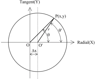
この円筒が歯車における基礎円(Base circle)である.Figure 1.2は,インボリュー ト歯形の測定原理である.
Measured curve
θ y
Theoretical curve
M T
y y
θ
y
d
bBase circle
Involute
TFigure 1.2 Basic principle of involute profile measurement
インボリュート歯形は,歯車をその回転軸が歯車測定機の回転軸と一致する ように取り付け,歯車の回転と共に,歯面に接触した測定子が基礎円と接する 作用線上を直線運動して測定できる.ここで,dbは基礎円直径,θは転がり角,
yは転がり長さを表す.そして,yの添え字としてTは理論値(曲線)を示し,
Mは測定値(曲線)を示す.理想的なインボリュート歯形の場合,基礎円に接 する作用線方向の転がり長さyTは式(1.1)で定義される.よって,インボリュー ト歯形は,測定子を歯車の基礎円接線上に配置して歯面に接触させ,歯車の回 転運動と測定子の直線運動を等速制御して測定することができることになる.
そのときの転がり角θと歯面上の実際の転がり長さyMを測定し,理論値との差 を算出することで,式(1.2) の歯形誤差曲線eprof(θ)が得られる.
θ
⋅
= 2
b T
y d (1.1)
( )
yM yTeprof θ = − (1.2)
歯形精度の評価項目には,国際規格(ISO1328-1)[8]やJIS規格(JIS B 1702-1)[9]
で定義された全歯形誤差 Fα,歯形こう配誤差 fHα,歯形形状誤差 ffα,があり,
得られた歯形誤差曲線によって評価される.無修正インボリュート歯形の場合 の歯形精度をFigure 1.3,Figure 1.4および Figure 1.5に示す.
全歯形誤差Fαは,Figure 1.3のように評価範囲において実歯形を挟む2つの 設計歯形曲線間の距離である.設計歯形とは,設計仕様と一致した歯形であり,
無修正インボリュート歯形の場合,Figure 1.2のように直線となる.歯形形状誤 差ffαは,Figure 1.5 のように評価範囲において平均歯形を平行移動して得られ る2つの曲線間の距離である.平均歯形とは,設計歯形から直線勾配を差し引 いて得られる曲線であり,平均歯形の位置および勾配は最小二乗法によって算 出される.歯形こう配誤差fHαは,Figure 1.4のように評価範囲の両端で平均歯 形と交差する設計歯形間の距離である.
Profile deviation
evaluation range
F
αtip root
Figure 1.3 Total profile deviation
Profile deviation
evaluation range
f
Hαtip root
Figure 1.4 Profile slope deviation
Profile deviation
evaluation range
f
fαtip root
Figure 1.5 Profile form deviation 2)歯すじの測定原理
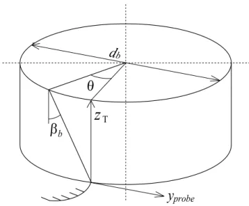
インボリュートヘリコイドは,円筒(基礎円筒)に巻き付けた紙に描かれた 直線が紙を巻いたり開いたりするときに描く曲面で,その直線と円筒軸がなす 角度が基礎円筒ねじれ角である.Figure 1.6は,歯車の歯すじの測定原理である.
歯すじ測定では,歯車をその回転軸が歯車測定機の回転軸と一致するように 取り付け,ピッチ円筒(またはピッチ円筒に近い円筒)上での理論上の歯すじ と実際の歯すじとを比較し,その偏差を算出するものである.歯すじ創成では,
平歯車の場合は被測定歯車のピッチ円筒上に測定子を置き,軸方向に歯車また は測定子を移動させて測定する.はすば歯車の場合は測定機に取り付けた歯車 を回転させ,ピッチ円筒上の理論上の歯すじの軸方向相当距離だけ歯車または 測定子を軸方向に移動させて測定する.この場合,歯車の回転角θに相当する 軸方向移動距離は,リードをLとするとLθ/2πである.
β
bz
Tθ d
by
probeFigure 1.6 Basic principle of helix measurement
基礎円筒上ねじれ角をβbとすると,歯すじ測定時の制御量zTは式(1.3)で定義 できる.そこで実際の移動量zMと,そのときの検出器の変位量yprobeを測定し,
式(1.4)の歯すじ精度曲線ehelix(θ)が得られる.
b b
T cot
2 ⋅θ⋅ β
= d
z (1.3)
( )
θ =y +(
zM −zT)
⋅tanβbehelix probe (1.4)
歯 す じ 精 度 の 評 価 項 目 に は , 国 際 規 格(ISO1328-1)[8]や JIS 規 格(JIS B
1702-1)[9]で定義された全歯すじ誤差 Fβ,歯すじ傾斜誤差 fHβ,歯すじ形状誤差
ffβ,があり,得られた歯すじ誤差曲線によって評価される.無修正歯すじの場 合の歯すじ精度をFigure 1.7,Figure 1.8およびFigure 1.9に示す.
全歯すじ誤差 Fβは,Figure 1.7 のように評価範囲において実歯すじを挟む 2 つの設計歯すじ曲線間の距離である.設計歯すじとは,設計仕様と一致した歯 すじであり,無修正歯すじの場合,直線となる.歯すじ形状誤差ffβは,Figure 1.9 のように評価範囲において平均歯すじを平行移動して得られる2つの曲線間の 距離である.平均歯すじとは,設計歯すじから直線勾配を差し引いて得られる 曲線であり,平均歯すじの位置および傾斜は最小二乗法によって算出される.
歯すじ傾斜誤差fHβは,Figure 1.8のように評価範囲の両端で平均歯すじと交差
Helix deviation
evaluation range
F
βtop bottom
Figure 1.7 Total helix deviation
Helix deviation
evaluation range
f
Hβtop bottom
Figure 1.8 Helix slope deviation
Helix deviation
evaluation range
f
fβtop bottom
Figure 1.9 Helix form deviation
3)ピッチの測定原理
歯車のピッチを測定する際,歯車はその回転軸が歯車測定機の回転軸と一致 するように取り付けられ,その回転軸と共に回転するロータリエンコーダとの 比較測定によってピッチ誤差が算出される.このとき,測定子は基準円上で歯 面と接する位置に置かれ,測定子の変位とロータリエンコーダの値が記録され る.そして歯車を回転させて,全歯にわたり歯面間の中心角を算出し,得られ た中心角に基準円半径を乗じて,基準円上の円弧長さに換算し,その理論値と の差からピッチ誤差は算出される.
ピ ッ チ 精 度 の 評 価 項 目 に は , 国 際 規 格(ISO1328-1)[8]や JIS 規 格(JIS B
1702-1)[9]で定義された単一ピッチ誤差 fpt,累積ピッチ誤差 Fp,部分累積ピッ
チ誤差 Fpkがある.それらの概要を Figure 1.10 に示す.単一ピッチ誤差 fptは,
歯丈のほぼ中央付近で歯車軸と同一の中心を持つ測定円周上で定義された軸直 角平面での実測ピッチと理論ピッチとの差である.累積ピッチ誤差Fpは,歯車 の全歯(k=1からk=z)領域での最大累積誤差であり,累積ピッチ誤差曲線の全 振幅で表現される.部分累積ピッチ誤差Fpkは,kピッチに対応する円弧の実際 の長さと理論長さの差である.理論的には,同じk ピッチ内の単一ピッチ誤差 の和に等しい.
Figure 1.10 Pitch deviations: ISO 1328-1 [8]
1.1.2 歯車測定機の研究開発
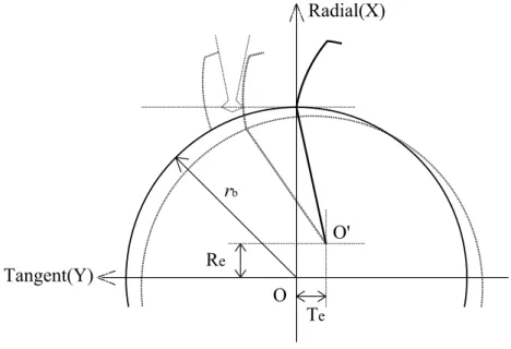
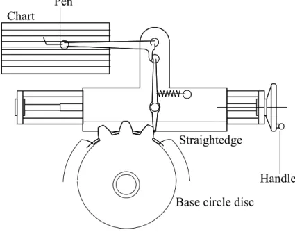
歯車精度の測定には,古くから専用の歯車測定機が使われており,その測定 原理は,精密な機械的創成運動あるいは幾何学的精密標準を基準とするもので あった.その1つである基礎円板方式は,被測定歯車の基礎円と同じ直径の基 礎円板と直定規を用いて歯形測定を行う測定機であり,測定原理をFigure 1.11 に示す.この方式は基礎円板と同軸上に被測定歯車を設置し,適度な力でその 基礎円板を直定規に接触させた状態でハンドルを回して直定規を送り,歯面に 接触した測定子の変位を歯形誤差として記録するものであり,インボリュート 創成原理を利用した簡単な構造である.
Pen
Handle Base circle disc
Straightedge Chart
Figure 1.11 Schematic drawing of involute testing instrument with a base circle disc その歯車測定機の供給元は,ヨーロッパ,米国,日本などの少数の専門メー カーに限られていた.これは,歯車測定機の製作には,機械,光学,電子,ソ フトウェア等を総合する極めて高い技術水準を要することや,大量生産品でな いため,市場規模が限定されていることによるものと思われる.歴史的にも,
歯車測定機の技術開発は上記3地域で独自に進展してきた経緯がある.特にド イツの国立物理工学研究所(PTB: Physikalish-Tschnische Bundesanstalt)では,歯車 の性能向上の重要性を認識し,他の地域に先んじて歯車精度の高精度化に関す る研究開発に注力し,厳密な幾何学的インボリュート創成が可能な高精度測定
装置を開発した.Figure 1.12は,その写真である.この装置は歯形基準器の両 側に同一寸法の高精度基礎円板を取り付け,高精度の真直度を持つ2列の直定
規(Straightedge)上を転がし,円板の転がり平面上で作用線方向に配置された検
出器で歯形測定する構造であり,基礎円板方式測定機の問題点である基礎円板 の回転精度や測定子移動の真直度などが解消された歯形測定の原器である.
1970年代になると,機械的創成機構を廃し,基礎円板の代わりに角度のデジ タルエンコーダ,作用線方向の移動距離計測には長さのデジタルエンコーダよ り取得したデジタル値を演算処理し,理論インボリュート曲線との偏差を算出 して歯形誤差を求める「演算式歯形測定器」が梶谷ら[10]によって提案された.
Figure 1.13は,その概略図である.そしてFigure 1.14は,その原理に基づいて
下条ら[11]によって開発された実験装置の構成図である.その装置は,被測定 歯車を回転させる主軸駆動部,基礎円に接する作用線方向に移動する測定ヘッ ド部およびデータ処理部により構成され,マグネセンサを用いてリニアエンコ ーダに原点を定めたことにより歯形誤差を歯面上のある基準点からの形状誤差 として計測できる特長がある.そして,主軸をパルスモータで回転させると歯 面に接触している測定子が約 100[gf]の測定力で作用線方向へ滑らかに移動し,
このときの回転角と直進距離を各エンコーダからデジタル値として取得し,デ ータ処理部のミニコンピュータで演算処理されて結果がXYレコーダまたはプ リンタに出力されるものであり,インボリュート曲線からの形状誤差のデジタ ル化が実現した.この結果を端緒に,さらに滑らかな誤差線図を得るためにエ ンコーダの高分解能化を図り,主軸と測定ヘッド部の運動をNC 制御すること で測定の自動化とデジタル化を実現し,産学連携の研究開発を経て1976年に世 界初のCNC(Computerized Numerical Control)方式歯車測定機が製品化された.
Artifact
Base circle
Straightedge
Stylus Base circle
Straightedge
Linear encoder
Stylus
Computer
Chart Rotary encoder
y
θ
Base circle
Figure 1.13 Schematic drawing of a digitized profile measurement [10]
Detector
Ⅲ
Detector
Ⅱ Detector
Ⅰ
Pulse motor
mini Computer (24K)
Tape reader
X-Y Recorder Z1
Z2 Rotary encoder
Worm
Stylus Linear encoder
Magnesensor
Synchronizer rb
Printer
Tape punch
Oscillo-pen
Motor driver
Calculator
Controller
Figure 1.14 Schematic drawing of an digitized experimental instrument [11]
このデジタルエンコーダとコンピュータによって歯車の誤差を出力する CNC方式歯車測定機は,日本が世界に先駆けて研究開発して製品化に成功した ものであるが,現在では世界の歯車精度測定機の主流方式になっている.
近年,歯車の高精度化の要求に伴い,研究機関や測定機メーカーでも高精度 歯車測定機の開発[11-17]が進み,実用化もなされている.誤差の検出方法につ いては,傷が付きやすい材質のプラスチック歯車などでは非接触方式測定の要 望が強く,それに応えたプローブや測定機も現れてきた.ただし,これらは測 定対象物の材質,形状,大きさ等に制約条件が有り,現時点において全ての測
定に対応できるのは接触方式測定である.しかし,歯車の校正については,各 国の国家計量標準研究所(NMI: National Metrology Institute)では,測定に三次元 測定機(CMM: Coodinate Measuring Machine)が使われている.中でもドイツの PTBでは,Figure 1.12の歯形測定原器に代えてFigure 1.15のようなCMMとレ ーザートラッカを組み合わせた計測システムで歯車の校正を行っている.
Figure 1.15 Schematic drawing of the CMM with laser tracer
このような状況において,高精度な歯車測定のためには,その使われ方(原 理)に合った測定方法である接触方式測定を基本とした CNC 方式歯車測定機 の測定精度向上を図ることが最も有効と判断して研究開発に取り組んできた.
しかし,歯車測定機の測定値を保証するシステムが整備されていないため,特 に高精度が要求される歯車の精度等級(測定値)の信頼性が保証されず,国際 的な取引や分業体制の進展を妨げている.そこで,歯車の精度を保証するため,
国際的に認められた歯車測定機の校正方法の標準化が必要不可欠となってきた.
1.1.3 標準化
歯車の精度が高くなると,その測定値に対する信頼性が大きな問題となり,
Figure 1.16 のような国家標準や国際標準によるトレーサビリティ体系[18]の確
立が必要になってきた.そこで,ドイツ,米国,日本のそれぞれの国家計量標
ものづくり業界において,ISO 9001[23],ISO/TS 16949[24]等の規格に要求さ れている品質保証は,国内外を問わずユーザ要求の中でも最も重要な事項であ る.実際に歯車業界では,アジア諸国の追い上げを受けており,知名度が低い 日本の中小企業にとっては品質を保証していくことが最重要課題となっている.
国家レベルでの歯車のトレーサビリティ体系が整えられると,同品質の歯車を 正当に価格的にも比較可能となり,歯車の適正コストが保証され,中小事業者 であっても業界へ新規参入しやすくなり,新規雇用者数の増加も期待できる.
National Institute
Calibration laboratory
Measuring room
Production floor Gears, splines Working artifacts Reference artifacts Primary artifact
Traceability
Increasin
g unc ertainty
Figure 1.16 Hierarchy of Gear calibration
以上のような背景から,故梅澤清彦博士(元東京工業大学教授)と久保愛三 博士(京都大学名誉教授)の提唱に基づき,(社)日本歯車工業会では,平成 9 年度に「歯車精度委員会(梶谷 誠委員長,他)」を設置した.同委員会は,前 述した歯車測定機の校正方法を国際標準として確立することを目指して,計量 標準やその認定制度,歯車測定機の校正方法に関する内外の実状を調査すると 共に,まずは歯形測定に焦点を絞り,その校正用基準器として,「長さ標準」と のトレーサビリティ確保が可能な基準器を模索した.その結果,円筒を組み合 わせた校正用基準器を試作して実験的な評価を行った.
一方,海外においては,米国歯車工業会(AGMA)がすでに歯車測定機の校正 方法に関する規格を有していることが明らかになった.そこでは校正用基準器 として,インボリュートアーティファクトと円筒基準器(Pin Master)を用いるこ ととしていたが,その AGMA 規格で使用する円筒基準器(Pin Master)は,先の
歯車精度委員会が検討していた校正用基準器と同等のものであった.そこで,
委員会では,試作した円筒基準器(Pin Master)を委員企業間で持ち回り測定し,
その有用性や問題点を実証的に明らかにした.また,事業の過程において,委 員会の事業計画が新エネルギー・産業技術総合開発機構(NEDO)の「新規産業支 援型国際標準開発事業」として平成10年度補正予算で採択され,(社)日本歯車 工業会は NEDO の委託を受けて「超精密歯車の精度の試験評価方法の標準化」
事業(プロジェクト)を実質的には平成11 年度から実施した.このプロジェク トでは,歯車精度の試験評価方法を確立し,それを標準化して国際標準として 提案することを目的として,次のような課題について研究を行った.
A 歯車精度の試験評価方法とその標準化に関する国内外の現状および 関連研究の動向の調査
B デジタル式歯車精度測定機の試験評価方法の研究
C フィールドテストによる評価とフィールドデータの収集 D 国際規格の骨子作成並びに国際標準化活動計画立案
歯車測定機の校正にはインボリュートアーティファクトなどの基準器を用い る必要があるが,その基準器の校正方法が重要な課題であり,プロジェクトで は,その目的の一つ(上記研究課題B)として校正用基準器を評価できるデジ タル式高精度歯車測定機の開発[12,13]に取り組んだ.そして,その歯形測定精 度を検証した結果[25],従来の歯車測定機と比較して高い繰り返し性が得られ,
全歯形誤差で約1[μm]の不確かさ[26]を持つことが分かった.しかし,更に細か く解析[27]していくと,その測定データには高い周波数の変動成分が含まれて おり,測定機に起因する誤差なのか測定した歯面の形状なのか区別することが できず,開発した歯車測定機は,1[μm]以下を十分に保証できる歯車測定基準機
(=校正機器としての歯車測定機)には至らなかった.
一方,大阪精密機械(株)歯車測定センター(GMC)は,2006 年には(財)日本適 合性認定協会(JAB)によって「歯車測定機の校正機関」に認定登録され,2008 年には(独)産業技術総合研究所計量標準総合センター(NMIJ)や(独)製品評価技 術基盤機構(NITE)等の指導の下で,計量法校正事業者登録制度(JCSS)[28]に沿っ て 国 際 標 準 化 機 構 及 び 国 際 電 気 標 準 会 議 が 定 め た 校 正 機 関 に 関 す る 基 準
(ISO/IEC 17025)[29]の要求事項に適合していると(独)製品評価技術基盤機構認
定センター(IAJapan)によって判断され,「歯車の校正機関」に認定登録された.
しかし,トレーサビリティ体系を確立・普及させ,歯車業界全体の利益や国際 競争力の強化,公平な競争原理によるコスト削減などの将来的な効果や社会貢 献に繋げるためには,より不確かさが小さく,歯車校正システムに組み込める
1.2 本研究の目的
以上,述べたように,多くの産業分野において歯車の高精度化が強く求めら れており,その歯車の精度を保証するために,これまでも歯車測定機の高精度 化に向けて多くの取り組みが行われてきた.しかし,その測定精度は 1[μm]以 上の不確かさを持ち,サブμmオーダの精度を十分に保証できていない.
歯車の精度等級は,国際規格(ISO1328-1)[8]やJIS規格(JIS B 1702-1)[9]で規格 化されており,その一例として,基準円直径50<d ≤125[mm],モジュール
6 5
.
3 <m≤ [mm],歯幅10<b≤20[mm]の歯車精度等級をTable 1.1に示す.規格 に対して歯車測定機の不確かさは相対的に大きく,小歯車になる程より小さな 不確かさである必要があり,事実上,高精度な等級の歯車を全て保証できる歯 車測定機は存在しないと言える.
Table 1.1 An example of gear accuracy grade
Accuracy grade 0 1 2 3 4 5
Total profile deviation Fα [μm] 1.7 2.4 3.4 4.8 6.5 9.5
Total helix deviation Fβ [μm] 1.3 1.9 2.6 3.7 5.5 7.5
Single pitch deviation ±fpt [μm] 1.1 1.6 2.3 3.2 4.6 6.5 Total cumulative pitch deviation Fp [μm] 3.4 4.9 7.0 9.5 14.0 19.0
歯車測定機の評価方法については,各国の大学や国家計量標準研究所で研究 され,ISO でも議論されている.その中で,歯車精度の分類(歯形,歯すじお よびピッチ)に対応した単純形状基準器の研究[30-43]も進められており,三次 元測定機や歯車測定機でのラウンドロビン(Round robin)検証も行われてきた.
しかし,現状の測定機の持つ不確かさの大きさのために測定結果には機差が生 じており,理論を裏付けるための実証にも影響している.また,三次元測定機 では,機構における駆動系の繰り返し性や再現性を重視し,機構が持つ誤差や 環境変化等によって生じる空間誤差は校正・補正する研究[44-46]が進んでおり,
同じ座標測定を行う歯車測定機においてもその方向性は一致すると考える.
そこで本研究では,歯車精度委員会において既に開発された高精度歯車測定 機の問題点を理論および実験から解析し,それらの解決策を見出して実験を行 い,その結果に基づいて測定機の機構や検出システムを改良し,さらに空間誤 差の校正・補正方法を開発して適用を図ることで,より不確かさが小さく,歯 車校正システムに組み込むのに十分な測定能力を持った高精度歯車測定機を開 発することを目的とした.
1.3 本論文の構成
本論文は,第1章から第6章で構成されている.
第 1 章「序論」では,近年の歯車加工精度向上から,歯車測定機にサブ μm オーダの測定精度が要求される現状を述べた.これまで歯車測定機の測定値を 保証するシステムが確立しておらず,歯車業界において国際的な取引や分業体 制の進展を妨げていた.そこで,歯車測定機の校正方法を国際標準として確立 することを目指す取り組みの一環として高精度歯車測定機が開発されたが,そ の測定精度に課題が残った.しかし,校正事業者登録制度(JCSS)による「歯車 の校正機関」は事業を開始し,より不確かさが小さく,歯車校正システムに組 み込める高精度歯車測定機が必要になった状況について述べた.
第2章「既存の高精度歯車測定機の評価」では,歯車精度委員会において開 発された高精度歯車測定機の評価結果から問題点を明確化する.また,その問 題点に対して誤差の原因を理論的に検討し,更に測定機での実験検証によって 誤差の原因を明らかにする.
第3章「直接駆動方式実験機の開発」では,第2章で明らかにした誤差原因 のうち,測定機の駆動機構に起因する誤差に対して,その方策となる新機構を 提案して開発する.そして,その新機構に適した制御方式の検討や制御性能の 検証を行い,インボリュートアーティファクトを用いた繰り返し性の評価によ って提案した新機構の有効性を示す.
第4章「新高精度歯車測定機の開発」では,第3章で開発した新機構を採用 し,歯車校正システムに組み込むことを目指して新たに高精度歯車測定機を開 発する.測定機の機構以外にも検出システムを改良し,不確かさを小さくする ために空間誤差の校正・補正方法を開発して適用する.そしてインボリュート アーティファクトおよび歯すじアーティファクトを用いて,繰り返し性や再現 性および測定精度について評価し,開発した測定機の有効性を示す.
第5章「歯車校正システムへの適用評価」では,第4章で開発した高精度歯 車測定機を JCSS 校正事業における不確かさ算出要領書に準じ,要領の見直し を図りながら測定能力を評価する.その測定能力を現在の歯車測定基準機の測 定能力と比較することで優位性を確認し,開発した測定機は歯車校正システム に組み込むのに十分な測定能力を持っているかどうかを検証する.
第6章「結論」では,本研究で得られた成果をまとめると共に,今後の課題 と展望について述べる.
第 2 章 既存の高精度歯車測定機の評価
2.1 開発経緯
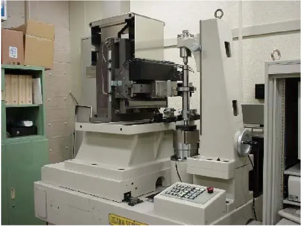
歯車測定機は,日本が世界に先駆けて CNC 方式を研究開発し,現在では世 界的に主流となっている.その高精度化に向けても各測定機メーカーによって 開発が進められているが,歯車測定機の校正方法が標準化されていないために 測定値が保証されていなかった.そこで,(社)日本歯車工業会では歯車精度委 員会を設置し,歯車の幾何学的形状・寸法の精度の試験評価方法の確立とそれ を標準化して国際標準として提案する事を目的とする研究開発プロジェクトを 実施した.そのプロジェクトにおいて,新エネルギー・産業技術総合開発機構
(NEDO)の委託を受けて,歯車測定機の校正用基準器を評価できることを目標と
した高精度歯車測定機を開発した[12,13].Figure 2.1は,その外観図である.
Figure 2.1 Photograph of the prototype GMM
2.2 システム構成
開発された高精度歯車測定機(試作機)の主な仕様を Table 2.1 に,構成を
Figure 2.2に示す.被測定歯車を回転させる主軸(C軸)と測定子を移動させる
ラジアル(X)軸,タンジェント(Y)軸,アキシャル(Z)軸の直交3軸から構成され,
C軸はウォームギヤや減速ギヤを介し,X・Y・Z軸はボールねじや減速ギヤ等 を介し,全ての軸をステッピングモータによって駆動している.そしてY軸ス ライド上に検出器が設置され,その先端に取り付けられた測定子を板ばねによ る軽い測定力で歯面に接触させた状態で測定を行う.
Figure 2.3は,歯形測定の概略図である.歯形測定時は,測定子の先端が歯面
に接触した状態で被測定歯車の回転運動と検出器のY方向直線運動が同期する ようにC軸とY軸をステッピングモータでNC制御し,そのときのC軸の回転 角 θ をロータリエンコーダで,測定子の移動量 yMを Y 軸のリニアエンコーダ と検出器に内蔵された差動変圧器(LVDT: Linear variable differential transformer) で検出する.そして歯すじ測定時は,歯形同様に測定子の先端が歯面に接触し た状態で,被測定歯車の回転運動と検出器のZ方向直線運動が基礎円筒上ねじ れ角βbに応じて同期するようにC軸とZ軸をステッピングモータでNC制御し,
そのときの C 軸の回転角 θ をロータリエンコーダで,検出器の移動量 zMを Z 軸のリニアエンコーダで計測し,同時に測定子の Y 方向変位 yprobeを検出器に 内蔵された差動変圧器で検出する.また,試作機はレーザ測長機を備えており,
それを用いて歯形測定時の測定子の移動量 yMや歯すじ測定時の測定子の Y 方
向変位yprobeを直接計測することで測定誤差を小さくできる.
Table 2.1 Major specifications of developed GMM
Maximum workpiece diameter [mm] 260
Maximum weight on board [kg] 20
Maximum measuring speed [mm/s] 10
Resolution of rotary encoder [pulse/rev] 7,200,000
Type of rotary encoder Glass disk
Resolution of linear encoder [μm] 0.1
Type of scale Glass scale
Resolution of detector (LVDT) [μm] 0.1
Resolution of laser interferometer [μm] 0.01
Type of motor Stepping motor
Worm gear
& Worm Wheel
Artifact
Rotary encoder
Stepping motor Laser
interferometer
Stepping motor
Stylus Ball screw
Detector
Tangential(Y) Axial(Z) Radial(X)
(C)
Air bearing Air slide
Spur gears
Coupling
Figure 2.2 Composition of prototype GMM
Axial Radial Tangent
Ball screw Linear encoder
Stepping motor (Tangent)
Cube corner
C
Laser
interferometer Air slide
LVDT Leaf spring
Rotary encoder
Stepping motor (C) Stylus
Worm gear & Worm wheel
Figure 2.3 Measuring method of tooth profile
2.3 測定精度の評価
2.3.1 評価方法
従来の歯車測定機の評価方法では,Figure 2.4のような(a)歯形基準器(インボ リュートアーティファクト),(b)歯すじ基準器(歯すじアーティファクト)お よび(c)ピッチ基準器(ピッチアーティファクト)を用い,第1章で示した歯車 精度規格(ISO1328-1, JIS B 1702-1)[8,9]に基づいて評価する.
各基準器の主な諸元をTable 2.2に示す.
(a) Involute artifact (b) Helix artifact (c) Pitch artifact Figure 2.4 Artifacts for verification of GMM
Table 2.2 Major dimension of involute and helix artifacts
Involute Helix Pitch
Base diameter [mm] 100 100 101.487
Face width [mm] 20 75 16
Helix angle [°] 0,15(RH/LH) 0,15(RH/LH),30(RH/LH) 0
Number of teeth 3 5 36
Dimension Type of artifact
しかし,高精度を目指した歯車測定機の評価においては,従来の評価項目だ けでは繰り返し性や再現性の向上が難しいと考え,形状ばらつきを示す標準偏 差を使って詳細に評価する.Figure 2.5は,その標準偏差を求める概念図である.
この図は繰り返し測定結果の一部を表しており,測定番号 i,測定番号(i+1)と 平均の誤差曲線を並べている.ε は平均形状と実形状との偏差を表しており式
(2.1)で表せる.次に,偏差の和が 0 になるように式(2.2)によって hijを求める.
ここでiは測定番号,jは評価範囲のデータ数を示す.そして,式(2.3)で相加平 均,式(2.4)で分散を算出する.標準偏差σはこの分散σ2の正の平方根である.
この標準偏差σを評価して歯形と歯すじの形状ばらつきを低減することで測 定精度の向上を図ることができる.そして,この測定方法で測定機の歯形・歯 すじの測定精度が向上するとピッチの測定精度も向上すると予測できる.
∑
=−
= n
i ij ij
ij e
e n
1
ε 1 (2.1)
∑
=−
= m
j ij ij
ij m
h
1
1 ε
ε (2.2)
∑∑
= == ⋅ n
i m
j
hij
m h n
1 1
1 (2.3)
( )
∑∑
= =− −
= ⋅ n
i m
j
ij h
m h
n 1 1
2
1
σ 1 (2.4)
Deviation curve of
measurement No.(i+1)
e
(i+1)(j+1)) 1 (j+
e
i je
(i+1)e
ijevaluation range Average deviation curve
Roll length
Deviation
ε
ijDeviation curve of measurement No. i
Figure 2.5 Schematic drawing of standard deviation calculation
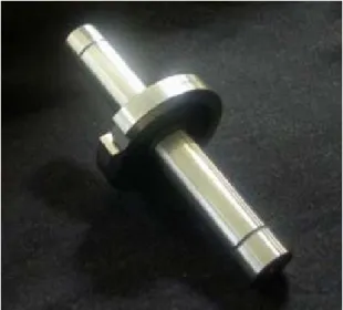
2.3.2 評価結果
試作機の重要な目的は,歯車測定機の校正に用いられるインボリュートアー ティファクト等の基準器を評価できる高精度歯車測定機を実現することであっ た.その測定精度評価においては,歯車基準器の歯形測定に特化し,全歯形誤 差と歯形こう配誤差について,主に測定の繰り返し性と再現性を評価した.繰 り返し性では同一条件での繰り返しに加えて測定速度の影響についても評価し,
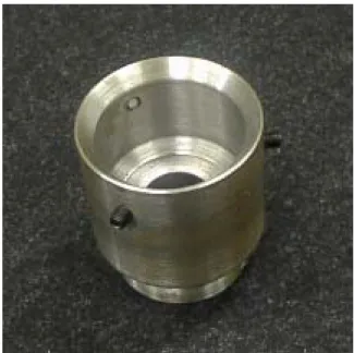
再現性では特に取り付け位相の影響について評価した.その評価にはFigure 2.6 に示すインボリュートアーティファクト(型式:JGMA988Master)を用いた.
この基準器は,鏡面仕上げされたインボリュート歯形の歯面を1つ持ち,通常,
歯車測定機の歯形測定精度の評価に用いられる.その諸元をTable 2.3に示す.
Figure 2.6 Photograph of involute artifact: JGMA988Master Table 2.3 Dimensions of involute artifact: JGMA988Master
Base diameter [mm] 98.800
Tip diameter [mm] 117.610
Normal pressure angle [°] 20
Tooth depth [mm] 10.5
Facewidth [mm] 20
また,測定条件として測定速度は3.0[mm/s]とし,円錐(エッジ)形状のφ3.0
となるC軸の回転角θは37.0[°],測定子の移動距離yMは31.90[mm]である.そ して,試作機の測定精度評価において,次の結果を得た.
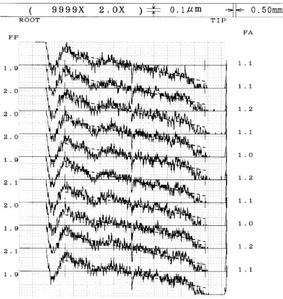
(1) 短時間(10 分程度)の 10回繰り返し測定における全歯形誤差 Fαおよび 歯形こう配誤差fHαの測定結果をFigure 2.7,解析結果をTable 2.4に示す.
その結果,ばらつき幅は0.2[μm]以下,標準偏差は0.1[μm]以下であった.
Figure 2.7 Results of ten measurements for about ten minutes Table 2.4 Repeatability for about ten minutes
Width of dispersion [μm] Standard deviation [μm]
Total profile deviation 0.2 0.094
Profile slope deviation 0.1 0.032
![Figure 2.13 Aliasing accompanying the sampling of a sine wave [47]](https://thumb-ap.123doks.com/thumbv2/123deta/7734155.1711725/49.892.230.676.173.382/figure-aliasing-accompanying-sampling-sine-wave.webp)