i
博士学位論文
Analysis and Proposals for Advance of Automobile Air Conditioning System from the Perspective of Energy
Saving and Thermal Comfort
車載用パーソナルエアコンの省エネルギー性と快適 性側面からの分析と提案
2013
年12
月曾 楊
ZENG YANG
ii
博士学位論文
Analysis and Proposals for Advance of Automobile Air Conditioning System from the Perspective of Energy
Saving and Thermal Comfort
車載用パーソナルエアコンの省エネルギー性と快適 性側面からの分析と提案
早稲田大学大学院 環境・エネルギー研究科 環境・新エネルギー研究
2013
年12
月曾 楊
ZENG YANG
iii
Automobile has been seen a rapid increase over the past years and has been becoming a necessary transport tool in the modern society. However, the increase of automobiles gives us a lot of problems including energy shortage. Therefore, with the development of technology, the energy saving has been taken into account in the design of automobile. In term of automobile air conditioning system, the low-energy consumption and high comfort has been required increasingly by consumers. This project aims to force the function of air conditioning systems to provide comfortable conditions for the passengers and reduce energy consumption, especially for the electric vehicles.
Therefore, a concept of personal air conditioning system is proposed in this study to replace the traditional one. Using the representative car of Honda Company as the model, thermal properties of vehicle cabin are simulated by computational fluid dynamics software and experimental studies are carried out to validate the simulation results. Based on that, this thesis is summarized as the following four parts.
1. The heat flow properties in sealed cabin of automobile are simulated firstly and experimental studies are carried out to validate the simulation results. Using the car STEPWGN as a model, a simplified three-dimensional geometry with real dimensions is established to predict the heat flow distribution of cabin when car is parking in the summer sunshine. The natural convection and radiation heat transfer from environment to cabin are considered and the total heat transfer rate is calculated by software.
Transient temperature and velocity distribution at the central and horizontal plane are also analyzed respectively. It is shown that simulation results have good agreement with experimental data. The cabin temperature increases by time and the highest value is
iv regions of cabin.
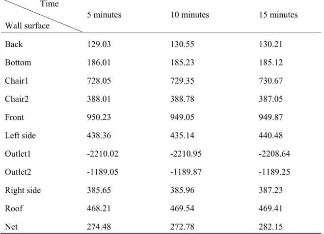
2. Based on the same methods of above, the cooling effect of traditional air conditioning of automobile is studied by numerical simulation and experimental validation. The experimental study has been taken place in a stable environment. The variation of temperature during 15 minutes is tested at different location of cabin and the energy consumption is measured, which makes a comparison with the numerical study. Using the representative car -N box as the model, the numerical study analyzes the air flow and heat transfer characteristics of inner cabin, especially at the place of wind outlet and inlet during cooling period. The results are in good agreement with experimental data.
However, under save energy model the traditional air conditioning system cannot make all the passengers feel comfortable. The rear row of cabin still has higher temperature than front row since it is difficult to carry out thermal exchange due to the complex structure of inner cabin.
3. A personal air conditioning system is proposed to instead of the traditional one. This new system is installed inside of each chair of vehicle cabin to provide thermal comfort for each passenger. Experiment validated that this system can make passengers feel comfortable after 4 minutes and all the apparatuses can just only consume electric power 338.8 W, which is less than the consumption of traditional air conditioning.
However, this system cannot make all the body feel comfortable. The numerical results have good agreement with experiment research. Except the area of chairs, the temperature of cabin has almost no change during 15 minutes. It indicates that this
v
4. In order to resolve the problem that personal air conditioning system just can be local action, a new modified personal air conditioning system is proposed by adding more four wind outlets in the front of cabin, which have bigger size and provide much more wind for all passengers. Based on the simulation calculation, the air flow and heat transfer characteristics of cabin are analyzed during 15 minutes. The results show that front wind outlets can work well to bring much cooling and put in motion the heat exchange among the cabin under the assist of wind outlets in chairs. The temperature of cabin can be dropped by about 5 ℃, which is consistent with the expectation of before.
Therefore, it demonstrates that this new modified personal air conditioning system can be used well in the future automobile.
Chapter 1
Introduction ... 1
1.1 Research background ... 2
1.1.1 Thermal environment in the cabin ... 2
1.1.2 Traditional automobile air conditioning ... 5
1.1.3 New personal air conditioning system ... 8
1.1.4 Current research condition ... 11
1.2 Research purpose and method ... 13
1.2.1 Research purpose... 13
1.2.2 Research method ... 13
1.3 Organization of this thesis ... 16
References ... 18
Chapter 2 Analysis of Heat Flow in Sealed Vehicle Cabin ... 21
2.1 Chapter Introduction ... 21
2.2 Solar intensity calculation ... 24
2.3 Experimental investigation ... 28
2.4 Numerical simulation ... 30
2.4.1 Governing equations and basis of algorithm ... 30
2.4.2 Model Geometry ... 34
2.4.3 Boundary conditions and problem setup ... 36
2.5.1 Validation of the results ... 39
2.5.4 Heat flow characteristics of whole model ... 46
2.5.5 Heat flow rate calculation ... 50
2.6 Conclusion ... 51
References ... 52
Chapter 3 Analysis of Heat flow in Vehicle Cabin with Traditional Air Conditioning System... 55
3.1 Chapter introduction ... 55
3.2 Experimental investigation ... 57
3.3 Numerical simulation ... 60
3.3.1 Model geometry ... 60
3.3.2 Boundary conditions and problem setup ... 61
3.4 Results and discussion ... 66
3.4.1 Validation of the results ... 66
3.4.2 Heat flow characteristics of whole cabin ... 73
3.4.3 Heat flow calculation ... 82
3.4.4 Energy consumption calculation ... 85
3.5 Conclusion ... 86
References ... 87
Chapter 4 Analysis of Heat Flow in Vehicle Cabin with Personal Air Conditioning System ... 89
4.1 Chapter introduction ... 89
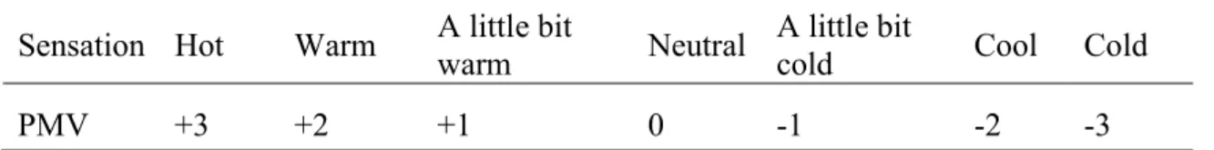
4.2 Evaluation of thermal comfort ... 91
4.3.2 Specification of instrument ... 99
4.3.3 Experimental method ... 102
4.4 Numerical simulation ... 104
4.4.1 Model Geometry ... 104
4.4.2 Boundary conditions and problem setup ... 106
4.5.1 Validation of the results ... 108
4.5.2 Heat flow characteristics of chair ... 114
4.5.3 Turbulence characteristics of chair ... 116
4.5.4 Heat flow calculation ... 120
4.5.5 Energy consumption calculation ... 122
4.5.6 Evaluation of thermal comfort ... 122
4.6 Conclusion ... 124
References ... 125
Chapter 5 Proposal of Modified Personal Air Conditioning System ... 127
5.1 Chapter introduction ... 127
5.2 Numerical simulation ... 129
5.2.1 Model geometry ... 129
5.2.2 Boundary conditions and problem setup ... 130
5.3.1 Heat flow characteristics of whole cabin ... 133
5.3.2 Heat flow calculation ... 139
5.4 Conclusion ... 143
Conclusions and Further Work ... 145
6.1 Conclusions ... 145
6.2 Further Work ... 148
6.2.1 Cooling load calculation of cabin ... 148
6.2.2 Experimental validation ... 149
6.2.3 Engine exhaust heat recovery ... 149
References ... 151
Acknowledge ... 153
List of publication ... 154
1
Chapter 1
Introduction
Automobile has been seen a rapid increase of over the past years and has become a necessary transport tool in the modern society. However, the increase of automobiles gives us a lot of problems including the environment pollution and energy shortage.
Nowadays the energy shortage is really serious problem and it tends to more serious.
Therefore, with the rapid development of the technology, the energy saving has been taken into the account in the design of an automobile to resolve the energy shortage problem. In term of automobile air conditioning system, the low-energy consumption and high thermal comfort have been required increasingly by consumers.
2
In order to enhance the performance of automobile to satisfy customers and improve the thermal comfort for passengers, there is plenty of necessary information that should be mastered as the basic data. For example, thermal resource of vehicle cabin, heat flow properties and temperature distribution of cabin, work performance of automobile air conditioning system and energy consumption and so on. All these analyses can help to design the high-efficiency air conditioning system to apply in the future vehicle, especially for the electric vehicle.
1.1 Research background
1.1.1 Thermal environment in the cabin
The main reason of thermal environment in the cabin is the effect by a variety of external disturbance and internal interference. Outside interference includes outdoor climate parameters, such as outdoor air temperature and humidity, solar radiation, wind speed, wind direction changes, which can be accessed through the shell to directly affect the indoor environment including passengers, lighting, equipment, etc. Therefore, in order to get a good indoor environment to meet passenger’s request, we must understand the car outside the main elements of climate variation and its characteristics.
The car has rapid response to the external environment changing as the small thermal inertia. Also, solar radiation is the primary source of heat on the ground and the main factors to determine the climate. Thus, the car air-conditioning load is the most direct affected by solar radiation. The solar radiation intensity can be calculated by the equation [1]:
3
Ix = I0 exp (-kx)
(1.1) Where
Ix, solar intensity at the distance of x from the atmosphere boundary;
I0, solar constant, I0 = 1353W/m2; k, a constant of proportionality, m-1;
x, the distance from the test location to the atmosphere boundary.
The calculation process of solar radiation intensity is shown in Fig.1-1. From this picture, we can see that the greater k the greater the attenuation of radiation intensity, so the value a can be expressed by:
a = kL
(1.2) Where
a, atmospheric specific extinction;
L, the distance when the sun on the top (solar radiation perpendicular to the ground) k, atmospheric specific extinction per unit thickness.
When the sun is located not on the top but the angle β, the distance of solar reach at the ground can be expressed as L/sinβ. The solar radiation intensity can be calculated by the equation:
In = I0 exp (-a/sinβ)
(1.3)
4 Where
In, the distances of solar reach at the ground;
β, position angle of sun.
Therefore, according to this equation, the solar intensity can be calculated at any time during a day.
Fig.1-1 Direct solar radiation intensity
Solar radiation getting into the cabin is an unsteady state heat transfer process; the temperature of outdoor is one important factor that cannot be ignored as it is also changing with the time. This hourly temperature is roughly cyclical changes by solar radiation. Thus its specific value has certain randomness, but from the overall trend, the temperature changes by cyclical. Considering from the design perspective of the thermal load, the temperature changes is also assumed to change according to a cyclical continuous rule. When calculating the air-conditioning, especially the heat transfer in the non-transparent car shell, the exterior surface of the shell suffers thermal effect by
5
both solar radiation and the air temperature of outside. Therefore, a synthesis temperature should be considered from both of them. The relationship between outdoor integrated temperature and solar radiation change with a 24-hour cycle is shown in Fig.1-2. Therefore, gain heat also changes according to this rule [2].
Fig.1-2 Circle change of outside temperature
1.1.2 Traditional automobile air conditioning
Human’s tolerance limits to high temperature may be related to his temperature sense, his ability to lose heat by regulatory sweating, and his ability to move heat from his body. There are many interrelating processes involved in heat stress. Pain receptors in man’s skin are triggered at a skin surface temperature of 46 ℃. Although direct contact with a metal surface at this temperature is painful and much higher dry air temperatures can be tolerated since the thermal insulation of the air layer around the skin is high.
Tolerance times of almost 50 min have been reported at a dry bulb temperature of 82 ℃.
6
In each case, the dew points were lower than 30 ℃. Many individuals are simulated by exposure to the 82 ℃. Therefore, in high temperature experiment like vehicle cabin, the air conditioning is important to make passengers comfortable. The automobile air conditioning system is a kind of device for refrigeration, heating, ventilation and air purification in the cabin, which is able to provide a comfortable environment for the passengers in any weather and driving conditions. A complete automotive air conditioning system depends on regulating the temperature, humidity, wind speed and ventilation, etc. to create a comfortable environment. The interior temperature is an important indicator of thermal comfort, which is decided by outside temperature, air flow, and solar radiation intensity. When the outside temperature is over 20 ℃, the car can only rely on air conditioning and refrigeration to achieve cooling purposes [3].
Traditional automobile air conditioning system is composed by the compressor, condenser, evaporator, expansion valve, receiver drier, hoses, fans, vacuum electromagnetic valve and so on, which can be seen in the Fig.1-3. Most of car have no independent motor for air conditioning system but depends on the car engine to provide motive power for the compressor. Therefore, the refrigeration performance is greatly influenced by the engine work with poor stability. Generally, the low-grade cars are using the traditional manual air conditioning which has a temperature control knob on the air conditioning control panel. Actually, this knob controls a variable resistance device which composes a series circuit with the resistor of temperature sensor in the evaporator. When the inside temperature changes, the resistance of this group circuit also changes by time, which controls the electromagnetic clutch of compressor depending on manual adjustment through knob. This kind of adjustment method is relatively simple, but the temperature control is not accurate enough. Modern high-
grade cars are more and more using the automatic climate control system automatically adjust the temperature of outlet
only pre-set temperature, which can control precision simple operation [4].
Fig. 1-3 Structure
7
more and more using the automatic climate control system the temperature of outlet according to the thermal flow of
, which can control precision of temperature
Structure of automobile air conditioning system
more and more using the automatic climate control system that is able to thermal flow of inside if of temperature just only by a
of automobile air conditioning system
8
Besides conduction and radiation heat, the engine, chassis, motors and other mechanical parts have emitted heat by conduction into the vehicle cabin. Therefore, the effect of automotive air conditioning has closely related to the heat insulation performance of body and window glass. In order to reduce the thermal load of air conditioning, it should pay more attention to the tightness and heat insulation property of vehicle cabin. Car air conditioning systems generally do not need special maintenance, but due to the impact of the external environment, the air purification equipment and air conditioning evaporator require regular cleaning to maintain good regulation of air quality [5].
Up to now, most of automobile are still using the traditional air conditioning system, which is easy to induce temperature gradient between the front row and back row.
Another new climate-control system is reported to use in the vehicle cabin to control the inner temperature, which is the most complex and thoughtful air conditioning system at present in the word. This kind of system is able to adjust the cabin temperature according to the outside and even it can divide the cabin into several parts and work for each part individually.
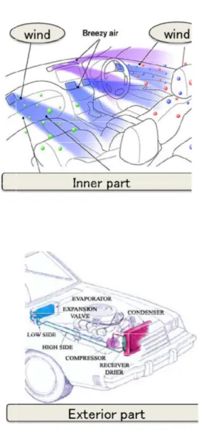
1.1.3 New personal air conditioning system
In recent years, a few companies have come out with a personal portable air conditioning that is light weight, battery-operated, and promises to cool down wherever people are. By means of this idea, a personal air conditioning system applied to automobile is proposal in this study. This system is designed by using the peltier module
which has become increasingly popular in the cooling research field.
appearance of peltier module is given in the Fig.1
Fig.1
Peltier is also called as s
technology of generating a negative resistance effect of material to create a heat flux between the
materials with consumption of electrical energy depending on the
current, which is similar with the heat pump that transfers heat from one side of the device to the other. The Fig.1
and falling cooler air (the blue device has flexible shape with and some other traditional high
personal air conditioning system in the automobile to save energy.
cooling capacity of this device is
9
which has become increasingly popular in the cooling research field.
appearance of peltier module is given in the Fig.1-4.
Fig.1-4 Appearance of peltier module
Peltier is also called as semiconductor refrigeration tablets which is a technology of generating a negative resistance. Peltier module just utilize effect of material to create a heat flux between the junctions of two different materials with consumption of electrical energy depending on the
current, which is similar with the heat pump that transfers heat from one side of the he Fig.1-5 has described the rising warmer air (the oran
blue part) on the surface of heat sink of a peltier model. This device has flexible shape with small size and does not need the refriger
and some other traditional high-energy consumption device so that it can be used as the personal air conditioning system in the automobile to save energy.
cooling capacity of this device is controllable via changing the input current and the which has become increasingly popular in the cooling research field. The structure
which is a refrigeration utilizes the peltier different types of materials with consumption of electrical energy depending on the direction of the current, which is similar with the heat pump that transfers heat from one side of the bed the rising warmer air (the orange part) part) on the surface of heat sink of a peltier model. This refrigerant, compressor t can be used as the personal air conditioning system in the automobile to save energy. Moreover, the via changing the input current and the
temperature control to within fractions of a degree can be maintain long life with mean time between failure exceeding one
However, there are plenty of restrictions
efficiency. Currently, the peltier device can typically produce a maximum temp
difference of 70 ℃ between its hot and cold sides. The more heat to be required, the less efficient it becomes since it needs to dissipate both the heat being moved and the heat it generates itself from its own power consumption.
application of low heat flux without high efficiency [7].
Fig.1-
10
temperature control to within fractions of a degree can be maintained. In addition, it has long life with mean time between failure exceeding one million hours [6].
are plenty of restrictions of using a peltier device in terms of , the peltier device can typically produce a maximum temp
between its hot and cold sides. The more heat to be required, the less efficient it becomes since it needs to dissipate both the heat being moved and the heat it generates itself from its own power consumption. Therefore, it has been relegated to application of low heat flux without high efficiency [7].
-5 Working schematic plot of peltier unit
n addition, it has hours [6].
of using a peltier device in terms of , the peltier device can typically produce a maximum temperature between its hot and cold sides. The more heat to be required, the less efficient it becomes since it needs to dissipate both the heat being moved and the heat it herefore, it has been relegated to
11 1.1.4 Current research condition
The performance of air conditioning system plays an important role to decide the comfortable level of an automobile and it has been paid extensive attention by a lot of researchers. For so many years, plenty of researches and experiments on the passengers' thermal comfort have been done in many automobile companies including Nissan, Honda and some other units of car. A brief review is given as the follows. Yamamoto and Hill [8] simulated the flow field in a truck by using a simplified mesh to obtain the air flow distribution. Wan and Kooi [9] used software to simulate the flow and temperature field in a car. They gained the optimal case for the air supply. Lin [10]
studied how the parameters affect the amenity, such as the wind volume rate and locations of air inlets. Kihler [11] used the zone calculation method to investigate the temperature field and the corresponding heat flux change with time and simulate the sunshine radiation into the cabin. Ishihara and Hara [12] measured the air flow velocity distribution by visualization and compared to their numerical simulation results.
Another analysis by them was the full scale model of a passenger compartment by using a laser light sheet method. Hagino and Hara [13] investigated the factors affecting the thermal comfort of cabin, like air temperature, air flow, and sunlight radiation and proposed a method to forecast passengers' thermal feeling. Currle [14] simulated the temperature field by STAR-CD and considered the passengers' thermal model to discuss the thermal comfort of cabin. Brown and Jones [15] create a thermal comfort model for the Ford Company, which considered the variation of temperature and velocity with time as well as the physiological status of passengers. Ambs made a simulation of the vehicle compartment climatic conditions to improve thermal comfort while reducing
12
vehicle development time and cost [16]. Gokhan and Muhsin added a virtual manikin model to make a three-dimensional transient numerical analysis to determine the air flow and heat transfer characteristics inside the vehicle cabin during a heating period [17]. Huajun Zhang built a numerical model to investigate the air flow and temperature fields inside a passenger compartment for improving thermal comfort and saving energy at the same time [18].
The researches mentioned above are mostly about the effects on passengers’ thermal comfort from air flow field, the temperature filed, heat transfer from outside to inside and radiation, etc. Study on the performance improvement of automobile air conditioning system is quite limited and it has suffered little attention by the researchers.
Therefore, the manufacture technology of automobile air conditioning system has little change in recent years. Actually, this field occupies more and more important position in the research of future automobile technology. The problems related to this grow more urgent, especially in the energy shortage countries.
13 1.2 Research purpose and method
1.2.1 Research purpose
This project aims to force the function of air conditioning systems to provide comfortable conditions for the passengers and reduce the energy consumption, especially for the electric vehicles. This kind of vehicle has limited electric power when driving on the road so that the air conditioning system should consume power as little as possible. Actually, the traditional air condition system consumes plenty of electric power. When cooling system turns on, the drive distance could be shortened by one third and this number could be a half when the heating system turns on. In order to solve this problem, the concept of personal air conditioning system is proposed in this study instead of the traditional one. This air conditioning system provides comfortable environment for each passenger individually by installed under each chair of vehicle cabin. By doing this, the energy wasting to cool the space of no person of cabin would be reduced dramatically. In addition, the appliance of this system is produced by Peltier module and fan motor that can only consume lower electric power to drive so that the saved energy can be used to provide vehicle to drive longer.
1.2.2 Research method
In this study, using the representative car of Honda Company as the model, a simplified three-dimensional geometry model with real dimensions and shape is
14
established to analyze the thermal transfer process by the computational fluid dynamics (CFD) software. The analysis of thermal transfer process is essential to deal with the thermal performance of cabin and provide comfortable conditions with high quality air for the passengers [19]. The first step has simulated the effect of solar to the cabin and a simple car model is used without any in-car facility and the computational domain only consists of the inner space of the cabin. Then, the chair and the air conditioning system have been considered in the model to calculate the temperature distribution and wind velocity in different directions, which is based on overall cabin and the air conditioning is operated. The third step has analyzed the thermal characteristics of cabin using the personal air conditioning system to replace the traditional one. To validate the simulation, the experimental studies with the same conditions are carried out to make a comparison. Finally, an optimized personal air conditioning system is proposed to resolve the shortage of previous one.
The numerical simulation process is shown as follows: First, a 3-D model of vehicle cabin is established by AutoCAD software and exported to CFD to generate mesh for numerical analysis, which is very curial to obtain the accurate predicted results. Then, the boundary conditions are set according to the thermal transfer properties and environment situation. Finally, the calculation is carried out by software and the analysis results are obtained [20]. Because of the complicated of the calculation and analysis we simplified the heat transfer process and presumed as follow: All the parts of the cabin are the same temperature at the beginning; just consider the solar radiation at the exterior shell of the car; ignore the radiation of interior wall surface in the cabin as their low temperature [21]. All the analysis is focus on the thermal flux and the simulation site was set at Tokyo Shinjuku, Japan, which can be seen in the Fig.1-6.
15
Fig.1-6. Parking location of car
16 1.3 Organization of this thesis
This thesis is organized as follows:
Chapter 1 presents the background of this research including thermal environment of the vehicle cabin, traditional automobile air conditioning system and the application of new personal air conditioning system. Moreover, the current research condition about the automobile thermal comfort and energy saving are introduced briefly from the year 1990 to 2010. In addition, the research purpose and method are given in this chapter.
Chapter 2 analyzes the heat flow distribution in the sealed cabin of automobile.Using the representative car of Honda Company-STEPWGN as a model, a simplified three- dimensional geometry with real dimensions is established to predict the heat flow properties of cabin when car is parking in the summer sunshine by CFD analysis software. The nature convection and radiation heat transfer from environment to cabin are considered and the distribution of transient temperature and velocity at the central and horizontal plane are analyzed respectively. The comparisons between predicted and tested temperature at pointed position of cabin is also presented and the total solar heat transfer is calculated by the software during 15 minutes.
The cooling effect of the traditional air conditioning of automobile is studied by numerical calculation and experimental validation in chapter 3. The experimental study has been taken place in a stable environment condition. The variation of temperature during 15 minutes is tested at different location of cabin and the energy consumption is also recorded, which makes a comparison with the numerical study. Using the representative car of Honda Company-N box as the model, the numerical study analyzes
17
the air flow and heat transfer characteristics of the inner cabin, especially at the place of wind outlet and inlet during the cooling period.
Chapter 4 proposes a new personal air conditioning system to instead of the traditional one. This new system is installed inside of each chair of vehicle cabin to provide thermal comfort for each passenger, which can help to resolve the energy consumption problem, especially for the electric vehicle. Numerical calculation and experimental validation are carried out in this chapter. Thermal transfer properties of vehicle cabin under using this system are predicted and the total heat transfer during 15 minutes is calculated by software. Thermal comfort and temperature experiment are validated to have good agreement with simulation results. In addition, the electrical consumption is tested to prove this system to be lower energy consumption.
In order to resolve the problem that personal air conditioning system just can be local action, a new modified personal air conditioning system is proposed in chapter 5. This modified system adds more four wind outlets in the front of cabin, which have bigger size and provide much more wind for all the passengers. Based on the simplified 3-D vehicle model, a numerical study has analyzed the air flow and heat transfer characteristics of cabin under the cooling action during 15 minutes. The energy consumption is estimated to compare with the traditional air conditioning system.
Chapter 6 concludes this thesis and sets the work in the future.
18 References
[1] YANG Rongxia, The research on calculation and experiment of the automobile air conditioner’s non-steady load, mater degree thesis of Lanzhou University of Technology, 2007.
[2] Richard C. Farmer, Gary C. Cheng, Yen-Sen Chen, Ralph W. Pike, Computational transport phenomena for engineering analyses, USA, 2009.
[3] Robert Parsons, ASHRAE handbook Fundamentals, 1997.
[4] Lou Kren, The History of Air Conditioning Properties, 2007
[5] A. Mezrhab, M.Bouzidi, Computation of thermal comfort inside a passenger car compartment, applied thermal engineering, 26(14-15): 1697-1704, 2006.
[6] Http://en.wikipedia.org/wiki/Main_Pag
[7] Thermoelectric Coolers Basics, TEC Microsystems, Retrieved 16 March 2013.
[8] K. Yamamoto, W.R. Hill, Interior flow visualization of a small pick-up truck and A/C Feeling Estimate, SAE International Congress and Exposition, ISSN: 0148-7191, SAE, Detroit, MI, USA, 1990.
[9] J.W. Wan, J. van der Kooi, Influence of the position of supply and exhaust openings on comfort in a passenger vehicle, Int. J. Vehicle Des. 12 (5–6): 588–597, 1991.
[10] Chao-Hsin Lin, A. Lelli Michael, Han Taeyoung, J. Niemiec Robert, C. Hammond Dean, Jr., Experimental and computational study of cooling in a simplified GM-10 passenger compartment, International Congress and Exposition, ISSN:0148-7191, SAE, Detroit, MI, USA, 1991.
19
[11] J. Kohler, Numerical calculation of the distribution of temperature and heat flux in buses under the influence of the vehicle air-conditioning system, ASHRAE Trans.
96(1): 432–446, 1990.
[12] Ishihara Yuji, Shibata Minoru, Hoshino Hiroshi, Hara Junichiro, Kamemoto Kyoji, Analysis of interior airflow in a full-scale passenger-compartment model using a laser-light-sheet method. International Congress and Exposition, ISSN: 0099-5908, SAE, Detroit, MI, USA, 1992.
[13] M. Hagino, J. Hara, Development of a method for predicting comfortable airflow in the passenger compartment. Worldwide Passenger Car Conference and Exposition, ISSN: 0148-7191, SAE, Dearborn, MI, USA, 1992.
[14] J. Currle, Numerical simulation of the flow in a passenger compartment and evaluation of the thermal comfort of the occupants, in: Proceedings of the 1997 International Congress and Exposition, ISSN: 1054–6693, SAE, Detroit, MI, USA, 1997.
[15] J.S. Brown, B.W. Jones, New transient passenger thermal comfort model, in:
Proceedings of the 1997 International Congress and Exposition, ISSN: 1054-6693, SAE, Detroit, MI, USA, 1997.
[16] Ambs, R: Improved Passenger Thermal Comfort Prediction in the Preprototype Phase by Transient Interior CFD Analysis Including Mannequins, SAE, 2002.
[17] Gokhan Sevilgen, Muhsin Kilic: Transient Numerical Analysis of Airflow and Heat Transfer in a Vehicle Cabin During Heating Period, Int. J. Vehicle Design, Vol. 52, Nos. 1/2/3/4, 2010.
[18] Huajun Zhang, Lan Dai, Guoquan Xu, Yong Li, Wei Chen, WenQuan Tao: Studies
20
of Air-flow and Temperature Fields inside a Passenger Compartment for Improving Thermal Comfort and Saving Energy. Part I: Test/ Numerical Model and Validation, Applied Thermal Engineering 29: 2022-2027, 2009.
[19] Massoud Kaviany, Essentials of heat transfer, USA, 2011.
[20] ANSYS Inc. Fluent Manuals.
[21] S. Mostafa Ghiaasiaan, Convective Heat and Mas Transfer, USA, 2011.
21
Chapter 2
Analysis of Heat Flow in Sealed Vehicle Cabin
2.1 Chapter Introduction
Recently, the parking car under solar radiation has been suffered a wide range of attention by plenty of researchers. There was reported that a baby alone locked in the car by parents had nearly died of heat stroke and exhaust due to the high temperature of cabin. It is well known that the temperature of sealed cabin tends to become
22
increasingly high along with time, which could conduct the terrible comfortableness when passengers enter into the car after long time parking [1]. Especially in the summer, the temperature of cabin can increase rapidly over 50 ℃, which could result in intelligent system device disable (IPAD and IPHONE, etc.) if these items are put inside the cabin. More serious is that the spontaneous combustion could be happened in the car because of the high temperature.
The reason why cabin under sunshine is a so dangerous place can be expressed by the heat flux attributing to the solar radiation [2]. Therefore, in order to improve the performance of vehicle air conditioning system, the thermal distribution of inside of cabin should be analyzed as the first step. In this chapter, the thermal characteristic of a sealed cabin is studied by numerical simulation and experimental validation. The numerical simulation has used the representative car of Honda Company—STEPWGN as model which is shown in the Fig.2-1 [3] and a simplified three-dimensional geometry with real dimensions has been established to analyze the heat flow distribution in a sealed cabin of car [4]. The heat flow distribution of cabin is predicted when car is parking in the summer sunshine by using the CFD analysis software. The natural convection and radiation heat transfer from environment to cabin are considered and the distribution of transient temperature and velocity at the central and horizontal plane are analyzed respectively. The experimental study has been carried out in a stable environment condition which is the same as the boundary conditions of simulation to validate the numerical calculation.
23
Fig. 2-1 Representative car of Honda Company—STEPWGN
24 2.2 Solar intensity calculation
The sunshine from environment can conduct energy which is separated into three parts: heat radiation, heat convection and heat conduct. Under the steady state conditions the energy equation from sun to the cabin based on the first law of thermodynamics is expressed as below [5]:
Q = �����+ ����+ �����
(2.1) Where
Q, total heat from sun;
�����, the part of heat through convection;
����, the part of heat through radiation;
�����, the part of heat through conduction.
However, the main energy access to cabin includes the heat radiation and heat convection. The heat conduction can be ignored. Accordingly, the calculation can be summarized in two parts: the radiation and the convection. The heat equation can be represented by the following equation [6]:
Q = �����+ ����
(2.2) Radiation is one of the basic mechanisms by which energy is transferred between regions of different temperature. It is distinguished from conduction and convection by the fact that it does not depend upon the presence of an intermediate material to act as a
25
carrier of energy. The radiation process can be explained as the consequence of energy- carrying electromagnetic waves. These waves are emitted by atoms and molecules as the result of various changes in their energy content. The amount and characteristics of the radiant energy emitted by a quantity of material depend upon the nature of the materials. Although the rate of emission of energy is not dependent of the surroundings, the energy transfer rate depends upon the temperatures and spatial relationships among the various materials involved. So how to calculate the radiation heat is the most important. The Fig.2-1 shows the thermal behavior of solar radiation through the glass of the car windows. The solar radiation is separated into radiation, glass absorption and penetration, which is defined constant thermal property. In order to calculate each value, we must check the solar thermal property and analyze the ratio of the each part in the entire solar outside. The thermal property of normal glass into the cabin can be discussed by this equation [7]:
Qs = Qr + Qa + Qp
(2.3) Where
Qs, the part of heat from solar radiation;
Qr, the part of heat through glass reflection;
Qa, the part of heat through glass absorption;
Qp, the part of heat through glass penetration.
In this equation, Qr can be expressed as ρQs; Qa can be expressed as αQs and Qp can be expressed as τQs. According to the general relationship of thermal radiation:
26 ρ + α + τ = 1
(2.4) Therefore, the solar radiation also can be expressed by:
Qs = ρQs + αQa + τQp
(2.5) Where
ρ, reflection rate;
α, absorption rate;
τ, penetration rate.
About the reflection ratio, we can put the sheet on the exterior of the glass and measure the reflection thermal from the glass.
Fig.2-2 Three approaches of sunshine through the glass
27
Fig.2-2 just shows the phenomena of radiation. Thus the situation is getting more complicated about the radiation and convective heat. We are supposed to take only radiation of each glass surface including the outside and inside into account in the first step. The calculation of thermal flow on the surface is just accorded to the natural property. In this study, all the radiation energy calculation can be done by the software which uses the governing equations to deal with the heat transfer through the boundary setting [8].
28 2.3 Experimental investigation
This experiment was carried out in the natural convection conditions. Ambient environment was quiescent without any winds. The relative humidity was determined at 60% and the ambient temperature stayed at 30 ℃. In order to avoid the direct sunlight causing too much high temperature, the test car was parking in the shade of trees.
Before starting the experiment, the engine of car was flameout to be cooling and all the doors were opened to make the in-car air flow to maintain almost same as that of outside environment. After one hour’s ventilation, the temperature of vehicle cabin can be considered the same as the ambient temperature and the car dashboard showed that the temperature was 30.1 ℃.
The experiment measuring time was set for 15 minutes in 5-minute intervals, which can be obtained three sets of data for one test. In order to eliminate accidental errors, the multiple measurements were performed and three sets of test were carried out due to time constraints. The infrared temperature probe was used in this experiment and the five measuring points were picked up to monitor the temperature variation of cabin.
Four points were fixed at the position of face when passengers sitting in the car including the front row and rear row. The part of face is very important place to feel if the environment is comfortable or not. Another measuring point is close to the
windshield which can help to study the affection of glass to cabin temperature. All the measuring points are given in the Fig.2-3.
29 p1
p2
p5
p3
p4
Top view p5
p1,p2 p3,p4
Side view
Fig.2-3 Measuring points of temperature in the vehicle cabin
30 2.4 Numerical simulation
A three-dimensional (3-D) CFD model of a vehicle cabin with real dimensions shape is used to determine heat transfer of solar radiation from environment. The analysis is fully transient and the computed flow and temperature distributions in the vehicle cabin included the interactions from turbulent flow, thermal buoyancy, and the three modes of heat transfer, i.e., radiation. Computed local heat transfer characteristics of the solar radiation and the flow and temperature fields at the different planes are discussed in this study.
2.4.1 Governing equations and basis of algorithm
In the numerical simulation, this software is based on the technique using a control volume theory to convert the governing equations to algebraic equations which can be solved numerically. The control volume technique works through integration of the governing equations about each control volume and generates discretization of the equations which keep each quantity based on control volume [9].
The algorithm for the numerical simulation can be carried out by the calculation equation which is based on the governing equations including the energy conservation equation, momentum conservation equation and mass conservation equation [10]. The energy conservation equation is written as follow:
31
∂(ρE)
∂t + ∇ ∙ �v��(ρE + p)� = ∇ ∙ �k���∇T − �� h�
�
J�
��� + τ�eff ∙ v���� + S�
(2.6) Where
h, enthalpy;
p, static pressure;
ρ, density;
v, velocity;
k���, effective conductivity (k + k�);
J�, the diffusion flux of species j;
k�, turbulent thermal conductivity;
τ�, stress tensor;
S�, defined volumetric heat sources.
In the equation, the first term on the left hand side represents unsteady energy and the second term represents the part of energy by conduction; the first three terms on the right hand side show the energy of conduction, species diffusion and viscous dissipation, respectively. The E and τ� can be expressed as:
E = h −��+���
(2.7)
32
τ� = μ �(∇ v�� + ∇v��T) −2 3 ∇v��I�
(2.8) Where
μ, molecular viscosity;
I, unit tensor.
The second term on the right hand side of the equation (2.8) is the effect of volume dilation. Therefore, the momentum conservation equation is given as follow:
∂
∂t(ρv��) + ∇ ∙ (ρv��v��) = −∇p + ∇ ∙ (τ�) + ρg�� + F��
(2.9) Where
F��, gravitational body force and contains other model-dependent source terms;
ρg��, external body forces.
Therefore, the mass conservation equation can be expressed as follow:
∂ρ
∂t + ∇ ∙(ρv��) = S�
(2.10) Where
Sm, the mass added to the continuous phase from the dispersed second phase and any user-defined sources.
This equation is the general form which is valid for incompressible and compressible flows. The realizable k-ε (2εqn) model is chosen for the turbulent modeling in this
33
calculation. This model is different from the standard model which may result in the minus normal stress. According with the physical laws of turbulence, the normal stress should be restrained by some mathematical ways and the realizable turbulent model is just derived from this theory. The turbulence energy equation can be expressed as follow [11]:
�(��)
�� +
�(����)
��� = �
������ +��
�����
���� + ��+ ��− �� − ��
(2.11)
�� = �����
�
(2.12)
�� = 1
�� + ���∙�/�
(2.13)
�� = √6cos ∅
(2.14) Where
Gk, the turbulence energy caused by the average of velocity gradient;
Gb, the turbulence energy caused by the buoyancy;
YM, the effect of total dissipation rating from the compressible turbulence expansion A0, empirical constant, in this equation, A0 = 4;
σ�, Prandtl number of turbulence energy.
34 2.4.2 Model Geometry
The geometry model of the vehicle was created by the AutoCAD software with real dimensions and shape. The CAD model of the vehicle cabin is given in the Fig.2-4.
However, this model was simplified and the computational domain only consists of the inner space of the cabin without the chairs and other in-car facilities, for example, the steering wheel. And then the model was exported to CFD software to generate mesh for numerical analysis, which is very curial to obtain the accurate predicted results. In the process, the hybrid structure grid including the tetrahedral and triangular elements was used in this mesh generation. The computational domain consists of 10199830 elements.
The mesh of numerical calculation zone is shown in the Fig.2-5.
35
Fig.2-4 CAD model of vehicle cabin
Fig.2-5 Surface mesh of numerical calculation zone
36
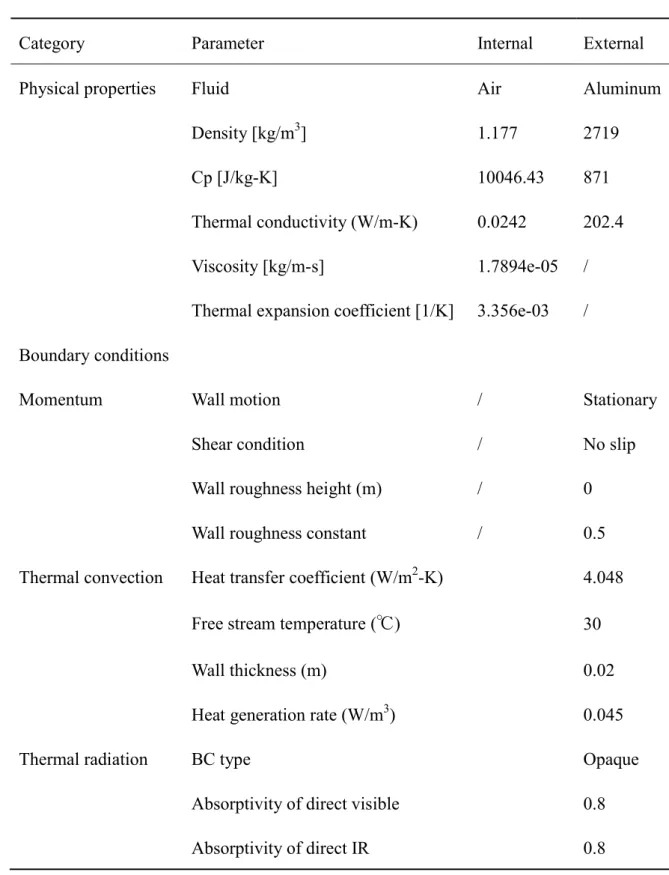
2.4.3 Boundary conditions and problem setup
The boundary condition also is an important factor to obtain the accurate results. In this numerical calculation, the surface boundaries were considered as solid walls including the roof, the bottom, the door and the windows, which were set as the stationary wall and semi-transparent. The outside thermal condition of the wall can be defined as a combination of convection and radiation from solar energy. The inner thermal flow can be considered as only natural convection from car shell.
On the one hand, the heat flux from environment caused the inner air temperature high and the major heat is generated by two major modes of heat transfer including the solar radiation and natural convection [10]. The solar radiation can be calculated by the solar ray tracing model of simulation software. The simulation starting date and time was set at the noon of the 21st in the June of 2012. According to the angle of sun in the sky, radiation heated level to the cabin can be gotten automatically. The direct and diffuse solar irradiations were presumed as constant value respectively. And the inner radiation of car shell was ignored. The heat of ambience transfers to car shell from air through natural convection and the environmental free stream temperature was set at 30 ℃ the same as experimental data. At the beginning of simulation, the boundary layer temperature of wall was equal to the environmental temperature at the outside edge of part close to the air flow. The thickness and heat generation rate of car shell was also considered in the calculation, which was important to predict the temperature variation of inner cabin.
On the other hand, the air flow of cabin moved as an internal circulation type depending on the thermal buoyancy, which was seen as natural convection. Therefore,
37
the Bousinnesq model was used in the calculation of air zone. Natural convection is the major cause for air motion in this sealed cabin and plays an important role in the energy transfer process from solar energy. Natural convection in the cabin can be represented in the type of internal circulation, which depends on the gravitation field to drive the air moving in the cabin [12]. Therefore, the gravity value had been set in the numerical calculation. The Bousinnesq model is appropriate for the analysis object whose temperature has kept within limits without any large change, which assumes the constant value of air density to carry out the iterative calculation [13]. All the setup and the boundary conditions are presented in the Table 2-1.
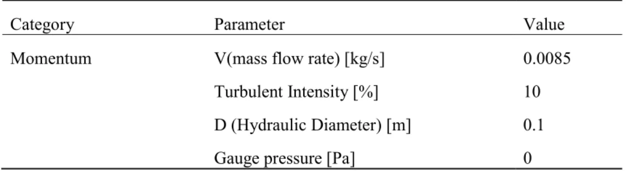
In the present work, the model domains were calculated using pressure-based solver with transient time and absolute velocity formulation. The energy and transport governing equations were discretized by the finite volume method and the SIMPLE algorithm was adopted for the coupling between pressure and velocity. The standard k- epsilon (2eqn) turbulent model derived from the instantaneous Navier-Stokes equations was chosen as the viscous model in conjunction with the standard wall function for the near wall region treatment in this simulation [14-15].
38
Table 2-1 Setup and boundary conditions
Category Parameter Internal External
Physical properties Fluid Air Aluminum
Density [kg/m3] 1.177 2719
Cp [J/kg-K] 10046.43 871
Thermal conductivity (W/m-K) 0.0242 202.4
Viscosity [kg/m-s] 1.7894e-05 /
Thermal expansion coefficient [1/K] 3.356e-03 / Boundary conditions
Momentum Wall motion / Stationary
Shear condition / No slip
Wall roughness height (m) / 0
Wall roughness constant / 0.5
Thermal convection Heat transfer coefficient (W/m2-K) 4.048
Free stream temperature (℃) 30
Wall thickness (m) 0.02
Heat generation rate (W/m3) 0.045
Thermal radiation BC type Opaque
Absorptivity of direct visible 0.8
Absorptivity of direct IR 0.8
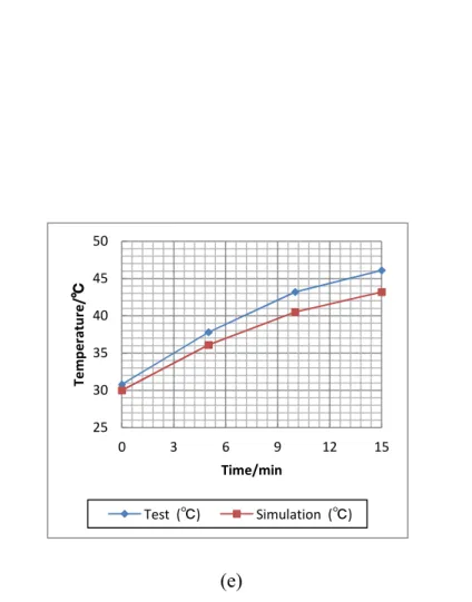
39 2.5.1 Validation of the results
The simulation results are validated by comparison of the predicted temperature values and the measuring data at the points located in the vehicle cabin described in the experimental investigation part, which is displayed in Figure 2-6. It can be seen that the predicted results are in good accordance with the experiment result and both of them present same trend with the time. The temperature shows a rapid increase before 5 minutes with the rate of nearly one degree per minute and it can reach about 35 ℃ after 5 minutes. This increased trend turns to slow down in the following 10 minutes and the final temperature can reach above 40 ℃ after 15 minutes. Especially, the temperature at the location close to the front windshield is measured over 46 ℃ which is very high and far more than the endurable degree of people. The two points located at same row show almost similar experimental and simulated temperature, individually.
In addition, from the figure it can be seen that at the back row (selected points p3 and p4), the differences between calculation and experimental temperature are about 1 ℃. At the front row (selected points p1 and p2), this value can be seen to stay at 2 ℃ in general.
However, the simulation results at the place close to windshield (selected points p5) show a worse agreement with measuring data, with the maximum deviation of 3 ℃ and the value has an increased trend with the time. Considering the parameters such as heat losses from the outside of cabin and heat transfer coefficient of car shell etc., there are too many factors affecting the numerical simulation. Therefore, such an agreement of a dynamic simulation results can be accepted to satisfy the engineering requirements.
40 (a)
(b)
25 30 35 40 45 50
0 3 6 9 12 15
Temperature/℃
Time/min
Test (℃) Simulation (℃)
25 30 35 40 45 50
0 3 6 9 12 15
Temperature/℃
Time/min
Test (℃) Simulation (℃)
41 (c)
(d)
25 30 35 40 45 50
0 3 6 9 12 15
Temperature/℃
Time/min
Test (℃) Simulation (℃)
25 30 35 40 45 50
0 3 6 9 12 15
Temperature/℃
Time/min
Test (℃) Simulation (℃)
42
(e)
Fig. 2-6 Temperature comparison of simulation results with experimental data, (a) P1; (b) P2; (c) P3; (d) P4; (e) P5
25 30 35 40 45 50
0 3 6 9 12 15
Temperature/℃
Time/min
Test (℃) Simulation (℃)
43
2.5.2 Heat flow characteristics of the central plane of vehicle cabin
The numerical result of the temperature distribution at the central plane of the vehicle cabin model is drawn in Fig.2-7. It can be seen that there is different temperature distribution in the cabin and the difference is simulated in the range of 8 ℃ after 15 minutes. The maximum average temperature stays about 43 ℃ at the location close to the wind glass and car shell including the front, top and bottom of cabin, Which is due to that the air flow around of these places are easy to be influenced by the heat concentrated in car shell from solar energy. The minimum average temperature remains at 35 ℃ at the rear cabin, which just occupies a little area of cabin. The temperature of most space stays at the range from 39 to 41 ℃.The simulation prediction of the velocity vector magnitude at the central plane of the vehicle cabin is shown in the Fig.2-8. It is easy to see that the air is essentially stagnant with low velocities in the cabin. However, the velocity at the central compartment is much lower than other regions. It can be said that the velocity is very important for maximizing heat transfer rate.
2.5.3 Heat flow characteristics of the horizontal plane of vehicle cabin
The heat flow field of the horizontal plane is shown in Fig.2-9. It can be seen that the temperature of horizontal plane stays in the same range with central plane and the minimum temperature region is still distributed at the rear cabin. However, the maximum average temperature occurs at the left and right side vehicle. The simulation result of the velocity vector magnitude at the horizontal plane of the vehicle cabin is presented in Fig.2-10. It is found that the air at the horizontal plane also moves with the
44
low velocity in the cabin. The minimum velocity is calculated at the front cabin with small area. There is a good agreement of region distribution between the temperature and velocity.
41
39
38 37
35 43
Fig.2-7 Numerical result of the temperature distribution (℃) at the central plane cabin
Fig.2-8 Numerical result of the velocity vector magnitude (m/s) at the central plane cabin
45
41
41
39
38
37
35
Fig.2-9 Numerical result of the temperature (℃) distribution at the horizontal plane cabin
Fig.2-10 Numerical result of the velocity vector magnitude (m/s) at the horizontal plane cabin
46
2.5.4 Heat flow characteristics of whole model
The heat flow transferred from the wall surface at a given temperature to the inner of vehicle cabin is obtained by solving the momentum and energy equations, which is derived under the assumption of constant material properties, but in reality the density, pressure and thermal conductivity of air will changes strongly with temperature. After 15 minutes numerical calculation, the reality thermal properties of the whole cabin can be observed directly from the results of the analysis through the graphics and plots. The pressure, density and temperature of the whole cabin are given in the Fig.2-11.
From these pictures, it can be easy to see that the pressure of the vehicle cabin has not any variation in the numerical time. The front row of cabin has higher temperature than other space, which is accorded with the report that the front row is the most dangerous space when the car parking under the sunshine because the radiation can enter into the cabin through the wide area of the front window glass. Also, the turbulent characters of front row are seen to be different from the other space, which is shown in Fig.2-12. The front row has higher turbulent intensity and bigger turbulent dissipation rate which can drive the air flow to move rapidly and cause the heat transfer from high temperature of wall to the low inner space, which can explain the reason why the front row has higher temperature than other space in the vehicle cabin. In addition, the wall fluxes has also shows much higher value in the front row and the solar heat flux shows stronger radiation at the surface of the vehicle, which is also agreement with the analysis about temperature characters before.
47
(a)
(b)
Fig.2-11 Thermal properties of whole cabin view, (a) Pressure (Pa); (b) Density (kg/m3)
48 (a)
(b)
49 (c)
(d)
Fig.2-12 Turbulent properties of whole cabin view, (a) Turbulent intensity (%); (b) Turbulent dissipation rate (m2/s3);(c) Wall shear stress (Pa);(d) Solar heat flux (W/m2)
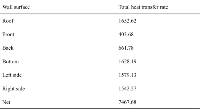
50 2.5.5 Heat flow rate calculation
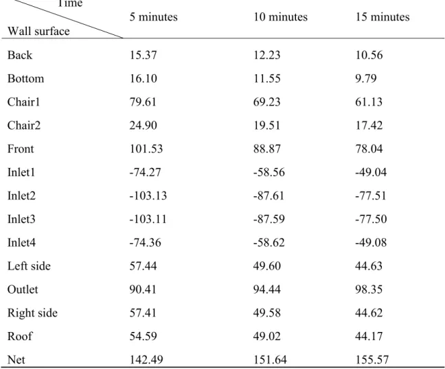
The total heat of cabin obtained from solar heat can be calculated by using the heat flow rate to multiply by the simulation time when car parking under sunshine. The total heat transfer rate of each wall surface of vehicle cabin after 15 minutes is shown in the Table 2-2. The whole cabin has got 112.02 kW heat in the 15 minutes. From this table, it can be easy to see that plenty of heat focuses on the roof of cabin due to the simulation time that is at noon when sun is just located right above of the roof. The bottom surface also has high heat can attribute to the height of bottom from ground is much too small so that the heat cannot flow fast and concentrate together.
Table 2-2 Total heat transfer rate at different direction (W)
Wall surface Total heat transfer rate
Roof 1652.62
Front 403.68
Back 661.78
Bottom 1628.19
Left side 1579.13
Right side 1542.27
Net 7467.68