Study on bonding mechanism and properties evaluation in
diffusion bonding of magnesium/aluminum alloys
Ming Zhao
Saitama Institute of Technology
Contents
Chapter 1 Introduction ... 1
1.1 Background and significance ... 1
1.2 The development and application of magnesium alloy ... 3
1.2.1 The development status of magnesium alloy ... 3
1.2.2 The application of magnesium alloy ... 4
1.3 Magnesium alloy welding research status ... 7
1.3.1 Arc welding ... 8
1.3.2 Laser beam welding ... 11
1.3.3 Friction stir welding ... 14
1.3.4. Electromagnetic welding ... 16
1.3.5 Diffusion bonding ... 18
1.4 Application prospect of this topic ... 21
1.5 Summary ... 21
References ... 22
Chapter 2 Experimental Materials and Methods ... 30
2.1 Introduction ... 30
2.2 Experimental base metal ... 30
2.3 Test equipment and technology... 35
2.3.1 Equipment and craft of diffused welding under pressure ... 35
2.3.2 Equipment and craft under no pressure diffusion ... 38
2.4 Sample preparation and corrosion ... 40
2.5 Experiment detection and analysis ... 42
2.6 Concluding remarks ... 44
References ... 45
Chapter 3 Organizational characteristics and interface strength on diffusion bonding of Mg-AZ31/Al-6061 under pressure ... 47
3.1 Introduction ... 47
3.2 Micro organizational structure on bonding interface under pressure... 49
3.2.1 SEM image of interface zone ... 49
3.2.2 XRD pattern structural characterization about intermetallic ... 50
3.3.3 EPMA element distribution of interface zone ... 50
3.3 Mg/Al alloy tiny structure observation under pressure ... 52
3.3.1 TEM analysis of structure and position orientation ... 52
3.3.2 EDS analyzes of Mg-AZ31/Al-6061 diffusion interface ... 55
3.4 Diffusion bonding strength of the Mg-AZ31/Al-6061 joint under pressure ... 56
3.4.1 Calculation tensile strength and maximum principal stress ... 56
3.4.2 Observe of tensile fracture ... 58
3.5 Concluding remarks ... 61
Chapter 4 Organizational characteristics and interface strength on diffusion bonding of
Mg-AZ31/Al-6061 under no pressure ... 65
4.1 Introduction ... 65
4.2 Organizational characteristics of the diffusion bonding interface ... 67
4.2.1 Division of diffusion interface on transition zone ... 67
4.2.2 XRD phase structure of diffusion interface on transition zone ... 69
4.2.3 Microstructure of diffusion interface on transition zone ... 70
4.3 TEM observation of diffused interface on transition zone ... 75
4.3.1 Refined structure of the transition layer in magnesium side... 75
4.3.2 Refined structure of the transition layer in Aluminum side ... 77
4.4 Analysis of optimized conditions on diffusion layer between magnesium AZ31 and aluminum 6061 alloys ... 81
4.4.1 Effect of bonding temperature on microstructure of welding interface and diffused layer hardness ... 81
4.4.2 Effect of holding time on intermetallic compound layer ... 84
4.5 Diffusion bonding strength of the Mg-AZ31/Al-6061 joint ... 86
4.5.1 Tensile strength of diffusion joint under no pressure ... 86
4.5.2 Influences on different process parameters to joint strength ... 88
4.6 Mg-AZ31/Al-6061 diffusion joint fracture and fracture analysis ... 92
4.6.1 SEM analysis of the joint fracture ... 92
4.6.2 Fracture analysis on diffused interface ... 94
4.6.3 Fracture process of diffused interface ... 96
4.7 Comparing Mg/Al diffused bonding under pressure and no pressure ... 98
4.8 Concluding remarks ... 99
References ... 100
Chapter 5 Discussion on bonding mechanism and simulation of bonding process... 102
5.1 Introduction ... 102
5.2 Mg/Al interface elements analysis of the theory of diffusion ... 103
5.3 Reaction kinetics of Mg/Al diffusion welding interface ... 109
5.4 Thermomechanical behavior of Mg-AZ31/Al-6061 diffused process ... 111
5.4.1 Elastoplastic constitutive equation ... 111
5.4.2 Thermal mechanical stresses analysis ... 115
5.4.3 Finite element model of thermal elastic-plastic analysis ... 119
5.5 The joint interface stress field simulation under different cooling parameters ... 130
5.6 Establishment of the joint mechanism and crystallization structure model ... 138
References ... 141
Chapter 6 Conclusions and recommendation ... 143
6.1 Conclusion ... 143
6.2 Recommendation ... 145
Related publications of the author ... 146
Chapter 1 Introduction
1.1 Background and significance
Nowadays, the increasing of energy and the environment pressure to save the limited earth resources and to reduce environmental pollution has become a very important focus which all of the world's countries have concerned. With the development of science and technology, the consumption of metal materials has risen sharply; the mineral resources of metal commonly used on the earth are becoming poor [1, 2]. One of the lightest engineering materials, magnesium alloy has a good thermal conductivity, easy processing and recyclability, and damping vibration, electromagnetic shielding and other functions [3]. Therefore, if possible magnesium alloy is used to replace a lot of aluminum alloy and steel structure material, the premise of guarantee product performance and product weight can be greatly reduced, it will greatly reduce the energy consumption and environmental pollution, it has huge market potential in the place such as aerospace, automobile transportation and electronic information [4]. In automobile industry, for example, studies have shown that the fuel used in automobiles and in which fuel of 60% was used in self-respect; the fuel was saved by 5.5% because of reducing 10% weight of the car. As demands are rising in the world, the car market competitions in the developed countries of auto manufacturers spend large sum of money on the research and development of the automotive lightweight materials [5]. Aluminum alloy materials used on automotive products at home and abroad, the development of lightweight play a dominant role in the production process of the car [6]. The magnesium alloy casting which used in the cars are growing fast and the consumption of the magnesium alloy has become the second in the consumption of the metal as while as the aluminum.
performance magnesium alloy, magnesium alloy structure is beginning to get application in all fields. Structural connection technology is indispensable to the widespread use of support, so the connection technology degree will directly affect the development of magnesium alloy in use process [7]. With magnesium and magnesium alloys used in various industries, the rapid growth of magnesium and magnesium alloy connection problems aroused people's great attention, but the welding performance of magnesium alloy is not well, it is difficult to achieve a reliable connection and become the bottleneck that restrict the application of magnesium alloys technology and become the key technology of presses for solution.
1.2 The development and application of magnesium alloy
1.2.1 The development status of magnesium alloy
With the development of science and technology, the consumption of metal materials had raised sharply, the current commonly resources on the earth has been affected [12]. The material of the new century mainly include that rich resources, energy conservation and environmental protection, in which light weight and high strength material conformed to the material requirements of the new century, development of Mg alloy is one of the most promising green new structural materials [13-16]. Mg in sea water accounts was about the earth's crust of 2.3% and reserves was bout 2.1x10¹⁵t, which have significant reserves of Mg in salt lake.
Main research and development of Mg, plasticity and toughness of the material in surrounding, corrosion resistance and fatigue resistance and so on comprehensive performance were developed; new type of Mg alloy can be prepared through adoption of new alloy elements and new corrosion process [17-20]. Development important equipment is suitable for mass production of Mg alloy; in which the development of new type high performance Mg alloy system; the atmosphere of Mg alloy smelting process protection, the flame retardant Mg alloy technology and surface treatment technology, and the problem of Mg alloy with the welding of dissimilar materials had been concerned in varieties fields.
retardant Mg alloy appeared as Mg alloy prepared technology was further improved; at the same time, Mg alloy melt environmental protection technology and Mg alloy micro-arc oxidation surface treatment technology emerged [21]. This phenomenon significantly promoted the applications of Mg alloy in automotive, aerospace and other fields.
1.2.2 The application of magnesium alloy
Mg alloy compared to other commonly materials of physical and mechanical properties are shown in table 1.1. Mg alloy has the outstanding performance characteristics to make its application prospect become more widely [22]. Mg alloy gradually replaces various structure steels, Al alloy and other material had been widely used in automobiles, electronics, communications and other civilian areas.
Table 1.1 Performance comparisons for several materials.
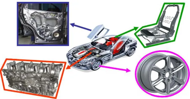
Mg alloy is applied in the car industry to meet the requirements of automotive safety, energy saving and environmental protection, the auto lightweight goals was effectively realized [23-28]. Car designer and production enterprises were achieved in recent years in order to reduce vehicle emissions pollution, improve fuel efficiency and reduce CO2 emissions; it was found that
the Mg alloy parts can significantly reduce vehicle weight, fuel consumption and the emissions of our fleet. The second generation of magnesium wheel yet only 514 kg decreased by 28% than the weight of aluminum wheel. For a car, 10% reduction in weight and fuel quantity can be reduced by 6% - 8%. The large-scale application of Mg alloy in the car production has more than 60 kinds of parts [29, 30]. The application of Mg alloys as components in the car as shown in figure 1.1.
Fig. 1.1 Application of Mg alloys as components in the car.
development.
1.3 Magnesium alloy welding research status
Welding and joining of magnesium alloys exert a profound effect on magnesium application expansion, especially in ground and air transportations where large-size, complex components are required. This applies to joints between different grades of cast and wrought magnesium alloys for dissimilar joints with other materials [35].
Due to specific physical properties of magnesium, the welding requires low and well controlled power input. Moreover, very high affinity of magnesium alloys to oxygen requires shielding gases which protect the liquid weld from an environment [36]. To magnify complexity, solid state reaction with oxygen forms a thermodynamically stable natural oxide layer on magnesium surface; the phenomenon is an inherent deficiency of joining. Both the conventional and novel welding techniques were adapted to satisfy these requirements, it is including that arc welding, resistance spot welding, electromagnetic welding, friction stir welding, electron beam and laser welding [37]. Since fusion welding has a tendency to generate porosities and part distortion, many alternative joining practices were implemented. These included that soldering, brazing, adhesive bonding and mechanical fastening [38]. However, the latter techniques have also disadvantages associated. For example, with stress induced by drilling holes during mechanical fastening, preheating during clinching or extensive surface was conducted in adhesive bonding [39]. Hence, experiments are progress with completely novel ideas of magnesium joining [40].
assemblies as well [41].
So far, the melting magnesium aluminum soldering welding in electron beam welding, magnetic pulse welding and resistance spot welding, TIG welding, MIG welding, laser welding, laser and electric arc welding, etc., the solid-state welding explosion welding, the common friction welding, friction stir welding, vacuum diffusion welding and brazing [42-48]. Domestic and foreign researches used generally magnesium alloy and aluminum alloy friction stir welding to made a certain progress. Now above research status of magnesium alloy and aluminum alloy welding points are as following:
1.3.1 Arc welding
There are two basic methods of arc welding. In an inert gas tungsten arc welding (TIG), an arc is generated between a non-consumable tungsten electrode and the welded metal. The electrode and welded metal are shielded with an inert gas. In general, welding can be made with or without filler. In this case, the filler is used and there is a form of wire in order to conduct the welding. For magnesium alloys, filler rods may be the same chemistry as welded part or lower melting range [49]. The latter allows the weld to remain liquid until other parts of the weld are solid, thus reducing the probability of cracking. During an inert gas metal arc welding (MIG), the arc is formed between the consumable electrode and the part to be welded [50]. The electrode is continuously provided from the spool. Both the welded area and the arc zone are protected by a gas shield.
m-1°C-1 and high thermal conductivity of 51 Wm-3K-1 make it susceptible to distortion during welding.
Table 2 Selected properties of AZ91 magnesium alloy, A6061 aluminum alloy,
ZA12 zinc alloy and AISI 304 stainless steel.
Property Units AZ91 A6061 ZA12 Steel304 Melting range °C 470-595 582-652 377-432 1400-1455 Density g cm-3 1.8 2.7 6.0 8.0 Modulus of elasticity GPa 45 68.9 83 200 Thermal conductivity (20°C) Wm-3K-1 51 180 116 16.2 Coefficient of thermal expansion (20-100°C) μm m-1°C-1 26.0 23.6 24.1 17.2 Specific heat (20°C) Jg-1°C-1 0.8 0.896 0.450 0.5 Latent heat of fusion pure base metals J/g 368 398 272 113 Electrical resistivity μΩm 0.0000143 0.00000360 0.00000610 0.0000720
arc welding (FATIG) when the welding path is coated with chemical fluxes [52]. In general, fluxes allow full penetration welding at greater rates using relatively inexpensive gas tungsten arc as the heat source. Using argon shielding and chloride fluxes, magnesium alloy welding tests showed an increasing in weld penetration as much as one hundred percent [53]. The deeper weld penetration was accompanied by higher heat input. Among several chlorides, including LiCl, CaCl2, CdCl2, PbCl2 and CeCl3, cadmium chloride was the most
effectively. Images of arc area during welding revealed that the heat flux from the arc appeared more concentrated towards the center of the pool with chloride additions.
The solidification microstructure of the weld is controlled depending on the thermal gradient and growth rate under cooling, [54]. The microstructure of MIG welded AZ91D alloy with AZ61 as welding wire were consisted of solid solution of α-Mg and intermetallic compound of Mg17Al12 [55]. The weld
contained roughly 7% of Al. In HAZ near the fusion line, subjected to temperatures between solidus and liquids, a part of α-Mg solid solution and eutectics distributed at grain boundaries and experienced melting. Thus, after subsequent solidification, the boundary regions formed islands of eutectic solid solution of α-Mg surrounded by Mg17Al12 precipitates [56]. The chloride fluxes
during welding using FA-TIG technique affected the weld microstructure. It appears that alloying from fluxes did not drastically affect on the solute partitioning during solidification. The AZ21 fusion zone, obtained with cadmium chloride fluxes, was significantly more dendrite than the zone of the alloy identically welded without fluxes. It is believed that differences in microstructure between welds with and without chloride fluxes are caused by thermal gradient [57-60]. During welding with cadmium chloride, the arc temperature was significantly higher and the liquid weld experienced higher constitutional under cooling.
where thick plates are welded using the metal inert gas technique. During MIG welding of 10 mm thick plates of AZ91D, two types of hot cracking occurred: solidification cracking of weld and liquation cracking in HAZ [61]. In general, solidification cracking takes place within a specific temperature range when a liquid film appears between dendrites. Solidification cracking occurred within the crater at the weld end and was caused by the high segregation of Mn, Al and Zn accompanied by high tensile stress. A frequency of both types of cracks increased at low welding speeds and was associated with high heat input and tensile stress. The experimental observations indicate that for MIG welding of magnesium alloys a reduction in the heat input reduces the frequency of cracks in weld and HAZ.
1.3.2 Laser beam welding
The term laser is an acronym for light Amplification by Stimulated Emission of Radiation. The solid or gaseous media are stimulated to emit a monochromatic, coherent source of light focused source and delivered to the workplace [62]. A delivery by hard optics explores mirrors and lenses for laser deflection and focusing. A limitation of hard optics is the short distance between the laser source and welded part. The use of fiber optics cable allows a longer separation of laser source. The latter is also more suitable for manipulation by robotics [63]. There are two major types of lasers, commonly used in industrial applications. The laser of Neodymium-doped Yttrium-Aluminum-Garnet explores a crystalline rod in the ultraviolet range with a wavelength of 1.06 μm. The CO2 laser is based on gaseous media and has a
wavelength of 10.6 μm.
weld. A shielding gas is used to protect the molten metal [64]. Welding may be created with or without a filler metal. As major benefits of laser beam welding, there are quoted: high travel speeds, minimal amount of heat added during welding, resulting in a small heat affected zone, low part distortion, no slag or spatter and great flexibility in tooling design.
Fig.1.2. Schematic of laser beam welding process.
The AM60 alloy, welding with a continuous wave CO2 laser formed a weld
with the narrow heat affected zone and no obvious grain coarsening [65]. The fusion zone was fine-grained with high density of Mg17Al12 precipitates. The
redistribution of elements occurred during welding with lower Mg and higher Al content in weld than that in the base alloy. A hardness of the fusion zone reached the higher level than the base alloy.
found more stable compared to welding of Al alloys, but its stability did not substantially affect the overall porosity. During CO2 laser welding of AZ31
wrought alloy, pores were found in welds mainly around the fusion boundary [66]. For wrought alloy, the level of initial porosity is relatively low; pore formation during welding is attributed to the surface contamination and hydrogen rejection from the solid phase during solidification. It appears that porosity is created due to a collapse of the keyhole and turbulent flow in the weld.
In recent, an analytical thermal model for welding the magnesium alloy WE43 was developed. Since laser welding is controlled by many parameters including that power, beam characteristics, welding speed, focal position, gas flow and material characteristics, the optimum is a complex task. The model allows determining the penetration depth and the bead width as a function of both the incident laser power and the welding speed. Modeling along with experimental verification was also used to study the keyhole formation and the geometry of weld profiles during welding of ZE41A-T5 alloy with Nd-YAG laser. Generally, the weld width and fusion area decrease with increasing welding speed [67]. It was found that the excessive reduction in laser power resulted in lower surface power density and change of the welding mode through partially penetrated keyhole to the conduction mode. There was no significant effect of the filler wire feed rate on the coupling and melting efficiency.
Hybrid laser beam technologies are defined as a combination of a laser beam source with an additional secondary beam source or another joining technique. A hybrid laser-TIG welding (LATIG) of AZ31 alloy achieved higher welding speed compared to that in laser or TIG welding. The penetration depth was twice for TIG and four times for laser welding. The same combination of laser beam and TIG was used to weld AZ31B magnesium alloy with mild steel by applying a nickel interlayer. As a result, semi metallurgical bonding was achieved. Along the Mg – Ni interlayer, the Mg2Ni phase with solid solution of
zone did not interact with solid solution, it is the mechanical bonding.
A new method of hybrid joining, called laser continuous weld bonding, was developed as an alternative to laser welding and adhesive bonding. The technique was successful in joining of AZ31B magnesium and A6061 aluminum alloys by reducing a volume of brittle intermetallic compounds of Al3Mg2 and Mg17Al12 phases which are formed in the fusion zone by reducing
the joint strength. The intermetallic phase formation was reduced because the fluid generated by the gasification of adhesives. It appears that the rising of adhesive vapor slows down the downward movement of liquid Mg, so that the content was reduced in the weld. Hence, the weld is composed of two-phase mixture with less intermetallic compound and more solid solution.
1.3.3 Friction stir welding
Friction stir welding is a relatively new joining technique and was invented in 1991 by the welding institute, England (TWI). It uses a rotating, non-consumable and cylindrical shouldered tool to deform the surrounding material without melting [68]. Thus, the joint is essentially formed in a solid state. Due to frictional contact of the tool and welded parts, the heat generated plasticize metal. As the tool moves forward, its special profile forces plasticized material to the back and the joint is formed because substantial forging force consolidates material. The process is accompanied by severe plastic deformation which involving dynamic recrystallization of the base metal.
and system stiffness requirements are quoted. Another drawback was a fixed pin capable handling of only one material thickness. However, modern solutions offer pins which can retract or expand within material, so that causing welding components with varying thickness.
The total energy generated per unit length of the weld E equals the energy because friction between the tool and the work piece Ef and the energy generated due to the plastic deformation of the work piece Ep:
p f sE E
E (1-1)
Where: s is the scaling factor introduced in order to control the effect of the energy from plastic deformation. The friction component Ef is expressed by:
0 2 0 2 0 3 1 2 h r r r F E i f (1-2)
ro is the radius of the shoulder, ri is the radius of the pin, h is the height of the
pin, ω is the pin angular speed, μ is the friction coefficient, F is the compressive force.
The technique of friction stir welding was applied to join magnesium with steel. During welding of AZ31 alloy and stainless steel 400, the rotation speed and pin axis orientation affected the microstructure and strength of the joint. The maximum strength of a butt type joint achieved approximately 70% of the strength measured for pure magnesium. The effect of tool geometry on microstructure and mechanical properties of Mg-steel welding was also studied. For brushed finished steel joints, the strength increased significantly with the probe length. Also microstructure was found to be sensitive to the probe length. The longer probe resulted in diffusion bonding while the shorter probe provided only the mechanical bond. The different observations were recorded for zinc coated steel where the probe length did not improve the joint strength. In that case, the short probe contributed to the defect-free joint.
1.3.4. Electromagnetic welding
Electromagnetic welding explores a phenomenon that current carrying conductors exert a force on each other as shown in Fig. 1.3. The force depends on the current direction and is repulsive for opposite direction flow and attractive for the same flow direction. In practice, the electric current in the coil creates an eddy current within the work piece which generates forces between the coil and the material placed within it [71]. During the welding process, these forces cause the outer work piece to plastically deform after accelerating towards the inner work piece, thus, a solid state weld was achieved. There are several modifications of magnetic welding which were successfully applied for magnesium. Similar concept of electromagnetic compression forming was used for processing of hollow profiles of magnesium alloys.
which surrounds the component to be welded. The eddy currents oppose the magnetic field in the coil and a repulsive force is created which drives the parts together at very high force speed and creates an explosive or impact type of weld. The eddy current i is expressed by the following equation:
t B i (1-4)
Where: κ and B are electrical conductivity and magnetic flux density, respectively.
Fig.1.3 Schematic diagram of electromagnetic pulse welding.
Where: Bo2 and Bi2 are magnetic flux densities at lower and upper surfaces of
welded sheet, μ is magnetic permeability, δ is the depth skin effect, given by the following:
2/ (1-5)
Where: ω is the angular frequency of changing field.
The sheets with a thickness of 0.5 to 1 mm were seam welded to produce a weld having the width of 5 mm. The weld thickness was 10% less than the original sheet thickness. It is believed that the weld zone is formed as a combined effect of heating by eddy currents and the strong impulse electromagnetic force (magnetic pressure). No clear fusion boundary in the joint interface was microscopically detected. The transition layer had the characteristic wavy shape without any significant heat affected zone.
The same concept called electromagnetic impact welding was used for 0.6 mm sheet of AZ31 magnesium alloy and 1 mm thick A3003 aluminum alloy. The differences in electrical conductivities of Al and Mg led to the skin depth of 0.7 mm in Al and 0.6 mm in Mg alloys [72]. The weld microscopy revealed a wavy interface and complete metal continuity without weld defects. Both x-ray diffraction and electron microscopy did not detect the intermetallic phase at the interface, it result showed a lack of melting. When welding was conducted at optimum conditions, failure during tensile testing occurred beyond the weld in the base metal.
The electromagnetic compression of tubular profiles with high electrical conductivity is an innovative joining process for lightweight materials [73]. The components are joined by using pulsed magnetic fields which apply radial pressures of up to 200 MPa. Since there is no contact between components to be joined, there is not possible to cause damage of the welded parts. The method was tested for aluminum alloys and has potentials for magnesium.
1.3.5 Diffusion bonding
typically conducted in a press; the heating was through conventional methods or induction units. Microwave sources are also explored for this purpose. To obtain high bonding, the surface should be clean and flat. There are three major stages of the bonding progress. First, a contact between materials occurs through the mating surfaces. During the second stage, diffusion within grain boundaries predominate eliminated pores and ensured arrangements of grain boundaries. During the third stage, the volume diffusion dominates and process was completed.
Diffusion bonding was found applicable for pure magnesium and its alloys. For pure magnesium rolled sheet, tests were carried out at the pressure range of 2-20 MPa, temperature range from 300°C to 400°C and time periods up to 72 h. The maximum lap shear strength was 0.888 at a bonding pressure of 20 MPa, temperature 400oC and for time of 1 h. A ductile fracture was revealed after the compression lap shear test [75].
finer grains the boundary diffusion has the higher contribution because more grain boundaries intersect with voids [77].
For dissimilar joints of Mg alloys, special importance is Al. the reason is the substitution of Al with Mg in automotive industry, which requires Mg-Al joints. An example is the Mg/Al joint was conducted under vacuum bonding at 460-480oC, time of 40-60 min and a pressure of 0.08-0.10 MPa. Hence, the diffusion zone was formed with two different transition regions on both sides. At the interface with Al, various MgxAly phases, such as Mg2Al3 and Mg17Al12
were formed. On the Mg side, Mg2Al3 phase was formed. The latter has fcc
structure as opposed to hcp of magnesium. It is claimed that Mg2Al3 phase has
the positive effect on cracking resistance of the joint.
The major obstacle during welding of Mg and Al is a formation at the interface between both alloys brittle compounds of Mg-Al, so that causing cracking during service [78]. Thus eliminating or improving interlayer is the critical factor in producing strong joints. One of possible solutions is to introduce an interlayer between Al and Mg for AZ31B and A6061 alloys, Zn interlayer was found to be effective. The Zn layer with a thickness of 60 μm was deposited on Al surface by hot dipping. The bonding was conducted at 360oC for 3 s.
Diffusion bonding was proved effectively for joining Mg with alloys having substantially higher melting ranges, such as Cu alloys. Joints made at the bonding temperature of 450oC, pressure of 12 MPa and time of 30 min exhibited shear strength of 66 MPa and bonding strength of 81 MPa [79].
The new technique of in-situ joint formation of magnesium cast and wrought components without necessity of welding was proposed at recently. The focus of this technique is to eliminate the natural oxide layer presented on magnesium and to replace it with metallic Zn/MgZn2 layer by a sequence of
with AJ62 cast alloy and pure Mg, an area-wide metallurgic in nature and defect free interface between both couples were revealed. The coating material dissolved into the bulk metal during casting. The issue of formation of shrinkage cavities at the interface can be solved by selecting appropriate solidification intervals.
1.4 Application prospect of this topic
According to micro structure and elemental diffusion for Mg/Al dissimilar metals on welding interface, the internal contact of Mg/Al metals welding craft and joint performance was revealed. The main experiment and theoretical basis was provided for the development of Mg/Al dissimilar metals basic craft. Whose metal structure has importance theoretical significance and practical value on automotive, aerospace, the application in the field of defense.
1.5 Summary
References
[1] K. Abderrazak, W. Salem, H. Mhiri, G. Lapalec, M. Autric. Modeling of CeO2
laser welding of magnesium alloys, Optics and Laser Technology, 2008, 40, 581-588.
[2] T. Aizawa, M. Kashani, K. Okagawa. Application of magnetic pulse welding for aluminum alloys and SPCC steel sheet joints, Welding Research, 2007,
86, 119-124.
[3] H. Al-Kazzaz, M. Medraj, X. Cao, M. Jahazi. Nd:YAG laser welding of aerospace grade ZE41A magnesium alloy: Modeling and experimental investigations, Materials Chemistry and Physics, 2007, 109, 61-76.
[4] P. Barreiro, V. Schulze. D. Loehe. Influence of process parameters on structure and mechanical properties of joints produced by electromagnetic forming and friction stir welding, Advanced Materials Research, 2008, 43, 47-56.
[5] W. Cai, P. Wang, W. Yang. Assembly dimensional prediction for selfpiercing riveted aluminum panenls, Inter. Journal of Machine Tools Manufacturing, 2005, 45, 695-704.
[6] Y. Chen, K. Nakata. Effect of tool geometry on microstructure and mechanical properties of friction stir lap welded magnesium alloy and steel, Materials and Design, 2009, 30, 3913-3919.
[7] C. Chi, C, Chao, T. Liu, C. Wang. Relational analysis between parameters and defects for electron beam welding of AZ-series of magnesium alloys, Vacuum, 2008, 82, 1177-1182.
[8] C. Chi, C. Chao. Characterization on electron beam welds and parameters for AZ31B-F extrusive plates, Journal of Materials Processing Technology, 2007, 182, 369-373.
Materials Characterization, 2007, 61, 703-712.
[10] A. Emam, E. Domiaty. A refined energy-based model for friction-stir welding, World Academy of Science, Engineering and Technology, 2009,
53, 1016-1022.
[11] J. Gilmore, V. Dunfold, G. Parteidge. Journal of Materials Science, 1991,
26, 3119-3124.
[12] G. Humpston, M. Jacobson. Principles of Soldering, ASM International, Materials Park, Ohio.
[13] F. Islam, M. Medraj. The phase equilibria in the Mg-Ni-Ca system, Calphad, 2005, 29, 289-302.
[14] J. Jia, A. Atrens, G. Song, T. Muster. Simulation of galvanic corrosion of magnesium coupled to a steel fastener in NaCl solutiion, Materials and Corrosion, 2005, 56, 468-474.
[15] R. Johnson, P. Threadgill. Friction stir welding of magnesium alloys, Magnesium Technology, 2003, 23, 190-198.
[16] S. Kore, J. Imbert, M. Worswick, Y. Zhou. Electromagnetic impact welding of Mg to Al sheets, Science and Technology of Welding and Joining, 2009,
14, 549-553.
[17] N. Kumbhar, K. Bhanumurthy. Friction stir welding of Al6061 alloy, Asian Journal of Experimental Science, 2008, 22, 63-74.
[18] K. Lee, S. Kumai, T. Arai, T. Aizawa. Interfacial microstructure and strength of steel/aluminum alloy lap joint fabricated by magnetic pressure seam welding, Materials Science and Engineering A, 2007, 471, 95-101. [19] Y. Li, P. Liu, J. Wang, H. Ma. XRD and SEM analysis near the diffusion
bonding interface of Mg/Al dissimilar materials, Vacuum, 2008, 82, 15-19. [20] L. Liu, J. Tan, X. Liu. Reactive brazing of Al alloy to Mg alloy using
zinc-based brazing alloy, Materials Letters, 2007, 61, 2373-2377.
[22] L. Liu, L. Xie. Adhesive bonding between Mg alloys and polypropylene, Materials Technology: Advanced Performance Materials, 2007, 22, 76-80. [23] L. Liu, J. Tan, L. Zhao, X. Liu. The relationship between microstructure and properties of Mg/Al brazed joints using Zn filler metal, Materials Characterization, 2008, 59, 479-483.
[24] L. Liu, H. Wang, Z. Zhang. The analysis of laser welds bonding of Al alloy to Mg alloy, Scripta Materially, 2007, 56, 473-476.
[25] L. Liu, Z. Wu. Microstructure and interfacial reactions of soldering magnesium alloy AZ31B, Materials Characterization, 2010, 61,13-18. [26] Y. Luo, G. You, H. Ye, J. Liu. Simulation on welding thermal effect of AZ61
magnesium alloy based on three-dimensional modeling of vacuum electron beam welding heat source, Vacuum, 2010, 84, 890-895.
[27] L. Ma, D. He, X. Li, J. Jiang. High frequency soldering of magnesium alloy AZ31B using Zn-Al filler metal, Materials Letters, 2010, 64, 596-598. [28] G. Mahendran, V. Balasuramanian, T. Senthilvelan. Influence of diffusion
bonding process parameters on bond characteristics of Mg-Al, Transactions of Nonferrous Metals Society of China, 2010, 20, 997-1005. [29] M. Marya, G. Edwards. Chloride contribution in flux-assisted GTA welding
of magnesium alloys, Welding Journal, 2002, 12, 291-298.
[30] M. Marya, G. Edwards. The laser welding of magnesium alloy AZ91D, Welding World, 2000, 44, 31-37.
[31] R. Neugbauer, C. Kraus, S. Dietrich. Advances in mechanical joining of magnesium, CIRP Annals - Manufacturing Technology, 2008, 57, 283-286.
[32] K. Papis, J. Loffler, P. Uggowitzer. Interface formation between liquid and solid Mg alloys - An approach to continuously metallurgic joining of magnesium parts, Materials Science and Engineering A, 2010, 527, 2274-2279.
[34] S. Park, Y. Sato, H. Kokawa. Effect of micro-texture on fracture location in friction stir weld of Mg allloy AZ61 during tensile test, Scripta Materialia, 2003, 49, 161-166.
[35] D. Poddar. Solid-state diffusion bonding of commercially pure titanium and precipitation hardening stainless steel, International Journal of Recent Trends in Engineering, 2009, 1, 93-99.
[36] V. Psyk, C. Beerwald, A. Klaus, M. Kleiner. Characterization of extruded magnesium profiles for electromagnetic joining, Journal of Materials Processing Technology, 2006, 177, 266-269.
[37] Y. Quan, Z. Chen, Z. Yu, X. Gong, M. Li. Characteristics of laser welded wrought Mg-Al-Mn alloy, Materials Characterization, 2008, 59, 1799-1804. [38] X. Qui, G. Song. Interfacial structure of the joints between magnesium alloy and mild steel with nickel as interlayer by hybrid laser-TIG welding, Materials and Design, 2010, 31, 605-609.
[39] H. Shi, R. Qiu, J. Zhu, K. Zhang, H. Yu, G. Ding. Effects of welding parameters on the characterestics of magnesium alloy joint welded by resistance spot welding with cover plates, Materials and Design, 2010, 31, 4853-4857.
[40] J. Skar, H. Gjestland, L. Oosterkamp, D. Albright. Friction stir welding of magnesium die castings, Magnesium Technology 2004, TMS, Warrendale.
[41] H. Somekawa, H. Hosokawa, H. Watanabe, K. Higashi. Experimental study of diffusion bonding in pure magnesium, Materials Transactions, 2001, 42, 2075-2078.
[42] H. Somekawa, H. Hosokawa, H. Watanabe, K. Higashi. Diffusion bonding in superplastic magnesium alloys, Materials Science and Engineering A, 2003, 339, 328-333.
[44] D. Sun, B. Lang, D. Sun, J. Li. Microstructure and mechanical properties of resistance spot welded magnesium alloy joints, Materials Science and Engineering A, 2007, 460, 494-498.
[45] D. Sun, D. Sun, X. Gu, Z. Xuan. Hot cracking of metal inert gas arc welded magnesium, ISIJ International, 2008, 49, 270-274.
[46] X. Wang, K. Wang. Microstructure and properties of friction stir butt-welded AZ31 magnesium alloy, Materials Science and Engineering A, 2006, 431, 114-117.
[47] T. Watanabe, K. Kagiya, W. Yanagisawa, H. Tanabe. Solid state welding of steel and magnesium alloy using a rotating pin, Quart. Journal of Japanese Welding Society, 2006, 24, 108-123.
[48] K. Westphal, T. Mulherkar, W. Schneiding. Joining of magnesium components using Al fasteners, Light Metal Age, 2005, 4, 2-3.
[49] J. Shang, K. Wang, Q. Zhou, D. Zhang, J. Huang, G. Li, Microstructure characteristics and mechanical properties of cold metal transfer welding Mg-Al dissimilar metals. Mater. Des. 2012, 34, 559–565.
[50] J. Wang, J. Feng, Y. Wang. Microstructure of Al-Mg dissimilar weld made by cold metal transfer MIG welding. Mater. Sci. Tech. Lond. 2008, 24, 827–831.
[51] I. Bhamji, M. Preuss, R. Moat, P. Threadgill, A. Addison. Linear friction welding of aluminium to magnesium. Sci. Technol. Weld. Join. 2012, 17, 368–374.
[52] H. Zhang, J. Song. Microstructural evolution of aluminum magnesium lap joints welded using MIG process with zinc foil as an interlayer. Mater. Lett. 2011, 65, 3292–3294.
[53] F. Scherm, J. Bezold, U. Glatzel. Laser welding of Mg alloy MgAl3Zn1 (AZ31) to Al alloy AlMg3 (AA5754) using ZnAl filler material. Sci. Technol. Weld. Join. 2012, 17, 364–367.
84–89.
[55] F. Liu, DRen, D.X.; Liu, L.M. Effect of Al foils interlayer on microstructures and mechanical properties of Mg-Al butt joints welded by gas tungsten arc welding filling with Zn filler metal. Mater. Des. 2013, 46, 419–425.
[56] L. Liu, F. Liu, M. Zhu. Study on Mg/Al weld seam based on Zn-Mg-Al ternary alloy. Materials, 2014, 7, 1173–1187.
[57] L. Liu, X. Liu, S. Liu. Microstructure of laser-TIG hybrid welds of dissimilar Mg alloy and Al alloy with Ce as interlayer. Scr. Mater. 2006, 55, 383–386. [58] F. Liu, H. Wang, L. Liu. Characterization of Mg/Al butt joints welded by
gastungsten arc filling with Zn-29.5Al-0.5Ti filler metal. Mater. Charact, 2014, 90, 1–6.
[59] L. Liu, F. Liu. Effect of Ce on microstructure and properties of Mg/Al butt joint welded by gas tungsten arc with Zn-30Al-xCe filler metal. Sci. Technol. Weld. Join, 2013, 18, 414–420.
[60] L. Liu, L. Xiao, J. Feng, Y. Tian, S. Zhou, Y. Zhou. The mechanisms of resistance spot welding of magnesium to steel. Metall. Mater. Trans. A 2010, 41, 2651–2661.
[61] G. Song, G. An, L. Liu. Effect of gradient thermal distribution on butt joining of magnesium alloy to steel with Cu-Zn alloy interlayer by hybrid laser–tungsten inert gas welding. Mater. Des, 2012, 35, 323–329.
[62] M. Gao, Z. Wang, X. Li, X. Zeng. Laser keyhole welding of dissimilar Ti-6Al-4V titanium alloy to AZ31B magnesium alloy. Metall. Mater. Trans. A, 2012, 43, 163–172.
[63] M. Aonuma, K. Nakata. Effect of calcium on intermetallic compound layer at interface of calcium added magnesium–aluminum alloy and titanium joint by friction stir welding. Mater. Sci. Eng. B, 2010, 173, 135–138. [64] P. Penner, L. Liu, A. Gerlich, Y, Zhou. Feasibility study of resistance spot
welding of dissimilar Al-Mg combinations with Ni based interlayers. Sci. Technol. Weld. Join, 2013, 18, 541–550.
strength steels. Steel Res, 1994, 65, 505–510.
[66] M. Alam, Z. Barsoum, P. Jonsén, H. Gblad, A. Kaplan. The influence of surface geometry and topography on the fatigue cracking behaviour of laser hybrid welded eccentric fillet joints. Appl Surf Sci, 2010, 256, 1936–1945.
[67] M. Alam, Z. Barsoum, P. Jonsén, H. Gblad, A. Kaplan. Fatigue behaviour study of laser hybrid welded eccentric fillet joints – Part II: State-of-the-art of fracture mechanics and fatigue analysis of welded joints. In: Proceedings of NOLAMP 12 conference, Copenhagen, Denmark; 2009. [68] M. Alam, Z. Barsoum, P. Jonsén, H. Gblad, A. Kaplan. The effects of
surface topography and lack of fusion on the fatigue strength of laser hybrid welds. In: Proceedings of ICALEO 28 conference, Orlando, Florida, USA; 2009.
[69] A. Hobbacher. Fatigue design of welded joints and components, IIW document XIII 2151-07/XV-1254-07.
[70] M. Alam, Z. Barsoum, P. Jonsén, H. Gblad, A. Kaplan. Geometrical aspects of the fatigue behaviour of laser hybrid fillet welds. In: Proceedings of fatigue design conference, Senlis, Paris, France; 2009. [71] A. Kaplan, P. Norman, G. Wiklund. The bifurcation flow chart as a method
for a generalised theory, applied to spatter defects during laser welding. In: Proc. 12th NOLAMP, Copenhague (DK), FORCE technology; 2009.
[72] M. Gao, S. Mei, X. Li, X. Zeng. Characterization and formation mechanism of laser-welded Mg and Al alloys using Ti interlayer. Scr. Mater, 2012, 67, 193–196.
[73] X. Qi, L. Liu. Fusion welding of Fe-added lap joints between AZ31B magnesium alloy and 6061 aluminum alloy by hybrid laser–tungsten inert gas welding technique. Mater. Des. 2012, 33, 436–443.
[74] S. Darwish, A. Ghanya. Critical assessment of weld-bonded technologies. J. Mater. Process. Technol, 2000, 105, 221–229.
factors for T and skewed T-joint plate connections. Int J Fatigue, 2000, 22, 573–584.
[76] H. Pang. Analysis of weld toe profiles and weld toe cracks. Int J Fatigue, 1993, 15, 31–36.
[77] H. Pang. Analysis of weld toe radius effects on fatigue weld toe cracks. Int J Press Vessels Pip, 1994, 58, 171–177.
[78] J. Ferreira, C. Branco. Influence of the radius of curvature at the weld toe in the fatigue strength of fillet weld joints. Int J Fatigue, 1989, 11, 29–36. [79] V. Caccese, P. Blomquist, K. Berube, S. Webber, N. Orozco. Effect of weld
geometric profile on fatigue life of cruciform welds made by laser/GMAW processes. Mar Struct, 2006, 19, 1–22.
Chapter 2 Experimental Materials and Methods
2.1 Introduction
For different welding joint, dissimilar metals diffused joint had different interface transition zone with different organizational structure and performance [1]. The organizational structure directly affect the weight of diffused welding joint, the formation depend on element diffused distribution nearby diffused interface, in which the organizational performance was comprehensive reflection of microstructure in transition zone [2]. With popularize and application of electron microscopy and electron microprobe techniques, the study on organizational performance reacted diffusion nearby interface became more thorough [3].
The paper was to study Mg/Al alloy joint strength and diffused organizational performance under pressure. The first, universal tensile testing machine was used to detect strength and calculate maximum principal stress under pressure. Scanning electron microscopy (SEM) was adopted to observe cut fracture form and micro structure in diffused bonding zone. By electron microprobe (EPMA) and X-ray diffraction (XRD), the element distributed on fusion zone and micro phase structure were detected and analyzed and lay the importance foundation for the depth study and popularize about Mg/Al alloy diffused joint micro organizational structure.
2.2 Experimental base metal
diffused bonding. The chemical composition of base metal was shown in Table 2.1 and Table 2.2. The specimens were polished with the #600 and #1200 sandpaper. In removing impurities process, the polished material was placed in the mixture of ethanol and acetone (the mixing ratio = 1:1) and kept 3min in the ultrasonic cleaner. Then the specimens were desiccated after being cleaned with water.
Table 2.1 Components of MgAZ31 alloy (wt. %).
Al Zn Mn Ca Si Cu Ni Fe Mg
2.5-3.5 0.5-1.5 0.2-0.5 0.04 0.1 0.05 0.005 0.005 Bal.
Table 2.2 Components of Al6061 alloy (wt. %).
Mg Zn Mn Si Cu Fe Ti Cr Al 0.9678 0.0005 0.0038 0.5527 0.2175 0.1401 0.0127 0.0718 Bal. 50mm 20mm 2mm 15mm Al-6061 Mg-AZ31 50mm 20mm 2mm 15mm Al-6061 Mg-AZ31
(a) Superimposed equipped mode
(b) Docking equipped mode
Fig.2.1 Sample processing size chart.
allotrope change. The crystal structure is shown in Fig.2.2. Magnesium alloys have a hexagonal lattice structure, which affects the fundamental properties of these alloys. Plastic deformation of the hexagonal lattice is more complicated than in cubic latticed metals like aluminum, copper and steel [4]. Therefore magnesium alloys are typically used as cast alloys, but research of wrought alloys has been more extensive since 2003. Cast magnesium alloys are used for many components of modern cars, and magnesium block engines have been used in some high-performance vehicles; die-cast magnesium is also used for camera bodies and components in lenses.
Crystal structure image of Mg Crystal structure image of Al
Fig. 2.2 Crystal structure image.
Table2.3 Thermo physical characteristic and mechanical property.
Aluminum is a relatively soft, durable, lightweight, ductile animal liable metal with appearance ranging from silvery to dull gray, depending on the surface roughness. It is nonmagnetic and does not easily ignite. Physical and mechanics performance as shown in Fig.2.2, Aluminum is a good thermal and electrical conductor, having 59% the conductivity of copper, both thermal and electrical, while having only 30% of copper's density. Aluminum is capable of being a superconductor with a superconducting critical temperature of 1.2 Kelvin and a critical magnetic field about 100 gauss (10milliteslas) [5]. Aluminum atoms arranged in a face-centered cubic (fcc) structure. Structural model as shown in Fig.2.3, Aluminum has stacking-fault energy of approximately about 200 mJ/m2. Alloys composed mostly of aluminum have been very important in aerospace manufacturing since the introduction of metal skinned aircraft. Aluminum-magnesium alloys are both lighter than other aluminum alloys and much less flammable than alloys that contain a very high percentage of magnesium.
diagram shows the aluminum solid solution (Al), the liquid phase L and the magnesium solid solution (Mg) at 470℃ produced in phase fields [9].
Under equilibrium conditions, the bonding could contain single-phase and solidification regions. However, reaction involving range of the R phase formed is very small under the temperature from 300℃ to 350℃. It is assumed that the structure of the solidified bonded zone present from 410℃ to 450℃, the formation of Mg17Al12 phase in the middle of the temperature range is more
noticeable in Fig. 2.3(a,b). The composition range for the Mg17Al12 phase has
been established, it is shown that the composition of the phase is from 45% to 60% according to the percents of Mg [10]. A composition range of 40% extends over a greater distance the Mg17Al12 phase has greater compositional
ranges [11]. It is results that Mg forms from low concentration phase to high concentration phase in turn. And when the concentration of Mg and Al is approximate, reaction formed Mg17Al12 phase. The eutectic Mg17Al12 phase
formed through the analysis of phase diagram under the temperature of 437℃. Therefore, bonded experiment could be carried out under the temperature. But also provide a theoretical basis for temperature setting in this study.
Fig. 2.3(b) Mg-Al-Zn alloy phase diagram.
2.3 Test equipment and technology
Adopting vacuum diffused welding process for Mg and Al alloy conducted welding. According to physical and chemical performance confirmed bonding process parameters under different craft conditions with pressure/no pressure.
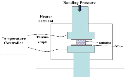
2.3.1 Equipment and craft of diffused welding under pressure
Fig. 2.4 Schematic of diffused bonding under pressure.
Fig. 2.5 Schematic of diffused bonding under pressure.
By the equipment of vacuum diffused welding, the different heating temperature, holding time and pressure adopted to conduct process experiment for Mg/Al diffused welding. Craft parameters were as shown in table 2.4 and bonding state under typical condition was as shown in Fig. 2.6.
Table 2.4 Temperature and pressure.
TRY 1 2 3 4 5
Temperature
(MAX) 480°C 420°C 430 °C 440 °C 440°C
KN(MAX) 1 0.5 0.28 0.07 0.16
diffused joint. Under reduced the heating temperature and pressure, bonding interface did not formed effective area contact the atoms in whose surface was not fully lead to effectively diffused connect was not formed.
Fig.2.6 Bonding state image under typical craft parameters.
The heating temperature was raised while reduced pressure, the base material did not produced plastic deformation and the brittle rupture phenomenon and could obtain good diffused joint. A large area of effective contact on the interface produced a certain atoms diffused bonding. It is shown that the good diffused joint may be obtained under the heating temperature and pressure [14]. According to above the experimental results of pressure diffused welding craft, the good diffused bonding joint was obtained under the heating temperature and diffused welding pressure 0.16MPa.
2.3.2 Equipment and craft under no pressure diffusion
In the diffusion welding process, Ar as protective gas was used. Flow meter was 150mm/hg. The optimization pressure craft parameters were obtained by a large of experiments. When the heating temperature was 440°C, the diffused effect was best. At the same time, the heating rate, holding time and cooling rate as three platforms under constant temperature for diffused effect to conduct analysis. Figure 2.9 was the process parameters curve of the heating rate, heating time and cooling rate.
Fig.2.7 Electric furnace schematic.
Fig.2.8b Bonding mode and homemade fixture.
Fig.2.9 Process parameters curve under heating time-cooling rate.
2.4 Sample preparation and corrosion
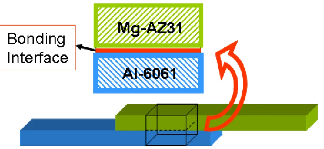
Fig 2.10 Pressurized joint specimens cut diagram.
Fig.2.11 No pressurized joint specimens cut diagram.
HNO3 solution or put sample coated with MgO style deerskin grinding paste; Al
side corrosion was carried out as a degree of HF 5% alcohol solution. Then the specimens were desiccated after water cleaning [15]. Subtle organization of diffused zone on diffused interface after corrosion treatment on the surface was observed. The specimen no corroded was applied to conduct elemental analysis and determination. The sheet specimen cut from Mg/Al diffused interface by FIB was used by transmission electron microscopy (TEM). The sampling position was shown in Fig. 2.12.
Fig. 2.12 TEM sampling position.
2.5 Experiment detection and analysis
The specimen after bonding was conducted tensile experiment by electronic universal testing machine, tensile equipment as shown in Fig. 2.13, tensile rate was 0.5mm/min. The tensile strength under pressure was as shown in Fig. 2.13.
the both ends of the text pieces are added with 2 mm thick metal gaskets. Principal stress was calculated by establishing Mohr’s stress circle model due to torque deflection easy to be produced in tensile process [16]. When the tensile strength under no pressure was detected, in order to further obtain accurate ultimate tensile strengths, butt joint diffused bonding was conducted under the same experimental condition to avoid produce torque deflection [17]. According to international standard ISO6898-2 made the specimen process a certain size as shown in Fig. 2.13.
Fig.2.13 Stress analysis of fracture interface.
strain was conducted by ANSYS software and to analyze the position easy to produce fracture and to statement for bonding mechanism according crystal structure.
2.6 Concluding remarks
References
[1] P. Sanders, J. Keske, K. Leong, G. Kornecki. High power Nd:YAG and CO2
laser welding of magnesium. J. Laser. Appl, 1999, 11, 96–103.
[2] K. Leong, G. Kornecki, P. Sanders, J. Keske. Laser Beam Welding of AZ31B-H24 Magnesium Alloy. In Proceedings of the ICALEO 98: Laser Materials Processing Conference, Orlando, FL, USA, 16–19 November 1998.
[3] B. Mordike, T. Ebert. Magnesium: Properties-applications-potential. Mater. Sci. Eng. A, 2001, 302, 37–45.
[4] M. Marya, D. Olson, G. Edwards. Welding of Magnesium Alloys for Transportation Applications. In Proceedings of the Materials Solution ’00 on Joining of Advanced and Specialty Materials, St. Louis, MO, USA, 9–11 October 2000, pp. 122–128.
[5] M. Pastor, H. Zhao, T. DebRoy. Continuous wave Nd:yttrium aluminium garnet laser welding of AM60B magnesium alloys. J. Laser. Appl. 2000, 12, 91–100.
[6] E. Aghion, B. Bronfin. Magnesium alloys development towards the 21st century. Mater. Sci. Forum, 2000, 350, 19–30.
[7] M. Marya, G. Edwards, S. Marya, D. Olson. Fundamentals in the Fusion Welding of Magnesium and Its Alloys. In Proceedings of the Seventh JWS International Symposium, Kobe, Japan, 20–22 November 2001.
[8] X. Cao, M. Jahazi, J. Immarigeon, W. Wallace. Review of laser welding techniques for magnesium alloys. J. Mater. Process. Technol, 2006, 171, 188–204.
[9] P. Liu, Y. Li, H. Geng, J. Wang. Microstructure characteristics in TIG welded joint of Mg Al dissimilar materials. Mater. Lett, 2007, 61, 1288–1291. [10] H. Baker, H. Okamoto. Alloy Phase Diagrams, 9th ed.; ASM International:
[11] J. Wang, Y. Li, P. Liu, H. Geng. Microstructure and XRD analysis in the interface zone of Mg-Al diffusion bonding. J. Mater. Process. Technol. 2008, 205, 146–150.
[12] E. Hajjari, M. Divandari, S. Razavi, S. Emami, T. Homma, S. Kamado. Dissimilar joining of Al Mg light metals by compound casting process. J. Mater. Sci. 2011, 46, 6491–6499.
[13] Y. Miyashita, R. Borrisutthekul, J. Chen, Y. Mutoh. Application of twin laser beam on AZ31-A5052 dissimilar metals welding. Key Eng. Mater. 2007,
353, 1956–1959.
[14] V. Firouzdor, S. Kou. Al-to-mg friction stir welding effect of material position, travel speed, and rotation speed. Metall. Mater. Trans. A 2010,
41, 2914–2935.
[15] S. Yutaka, H. Seung, M. Masato, K. Hiroyuki. Constitutional liquation during dissimilar friction stir welding of Al and Mg alloys. Scr. Mater. 2004,
50, 1233–1236.
[16] S. Hirano, K. Okamoto, M. Doi, H. Okamura, M. Inagaki, Y. Aono. Microstructure of dissimilar joint interface of magnesium alloy and aluminum alloy by friction stir welding. Quart. J. Jpn. Weld. Soc. 2003, 21, 539.
[17] S. Park, M. Michiuchi, Y. Sato, H. Kokawa. Dissimilar Friction-Stir Welding of Al Alloy 1050 and Mg Alloy AZ31. In Proceedings of the International Welding/Joining Onference-Korea, Gyeongju, Korea, 28–30 October 2002.
Chapter 3 Organizational characteristics and interface
strength on diffusion bonding of Mg-AZ31/Al-6061 under
pressure
3.1 Introduction
According to Mg/Al binary alloys phase diagram, it is known that Mg/Al substrates metal under a certain pressure formed Mg/Al eutectic by Mg and Al elements inter diffusion at 437°C in the heating temperature process. When AZ31 alloy and 6061 alloy together heating up to above eutectic temperature, eutectic phase would appear on contact surface, so that directly diffused effect for Mg/Al dissimilar metals conducted connection.
For craft aspect, the scale of the substrate metals under diffused reaction was difficult to control. Because eutectic was increasing in holding time, the process of eutectic formed was not stopped until only under the heating temperature reduced lower than eutectic temperature [1, 2]. But the joint performance was mainly decided through the reaction on joint interface. What reactions were produced and what were the amounts and form, in which distributed states for joint performance played a decisive role [3]. For Mg and Al dissimilar metals under pressure diffused bonding, eutectic phase of brittleness intermetallic compounds and simple phase formed diffused layers between substrates, so that controlling intermetallic compounds amount for improving joint performance played a key role before effectively bonding.
obtaining good performance diffused joint by the study of Mg/Al alloy diffused joint organizational performance under pressure had a importance significance [5].
3.2 Micro organizational structure on bonding interface under
pressure
3.2.1 SEM image of interface zone
SEM observation of bonding interface microstructure nearby the transition zone of diffusion bonding surface can reflect forming and structure, the bonded samples of Mg/Al dissimilar metals were cut and the microscopic sample was prepared [6]. The transition zone of diffusion bonding was taken by scanning electron microscopy (SEM) is as shown in Fig.3.1. Diffusion bonding surface of Mg/Al has obvious diffusion characteristics and the white brilliant and diffusion zone of new phase compound was formed between base metal of Mg and Al, in which organizational characteristics is different with the base metal [7]. It is indicated that new phase compound was formed with sloppy structure in the side of Mg interface transition zone and the new phase compound appear dense structure in the side of Al and it is quite evident that the plate exhibits a typical dendrites’ structure [8]. The pitting is uniform and the structure is rich, and a particle size exists in the range about less than 2μm. Mg/Al intermetallic compound formed under the condition of heating temperature and uniform apertures pitting is detected and the apertures pitting were small and distributed approximately uniformly. Finally, it is results that the structure is dense and uniform under pressure.
3.2.2 XRD pattern structural characterization about intermetallic
As shown in Fig.3.2, the results show that Mg17Al12 can be generated by
crystallites XRD analysis. As shown in Fig.3.2, the experimental results consist of multiple phases. Specifically, microstructure and the element concentration distribution analysis showed that Mg/Al intermetallic compound phase existed. In order to further research phase structure existed, the phase composition of Mg/Al dissimilar metals in diffusion interface was analyzed by X-ray diffraction experiment [9]. Cu-Kα target was adopted; working voltage is 40kV; working current is 150mA. It is results that Mg/Al intermetallic compound named Mg17Al12 phase was formed in transition zone of Mg/Al dissimilar metals after
diffusing [10]. The forming of Mg17Al12 is near the one side of Mg base metal
due to Al element neared Mg base metal accompanied empty seats and replacement diffusion mechanism; the diffusion bonding is more fully under pressure.
Fig.3.2 XRD patterns of bonding interface.
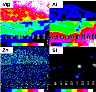
3.3.3 EPMA element distribution of interface zone
distribution in the transition zone of diffusion interface is as shown in the Fig.3.3. It is indicated that elements of Mg, Al, Si and Zn are mainly distributed in the transition layer. According to the distribution of Mg element and Al element, Mg and Al was obvious and was distributed separately between Mg side and Al side. Mg and Al elements mutual diffused to each side, so that reached a dense bonding [11]. The elementary distribution of Mg, Al, Si and Zn reflected the generation of Mg-Al-Zn alloy phase. The transition zone played the role of the mutual diffusion effect. The results are consistent with that of XRD analysis.
Fig 3.3 Elements face scan of the weld bonding of Mg to Al.
3.3 Mg/Al alloy tiny structure observation under pressure
3.3.1 TEM analysis of structure and position orientation
In order to further study phase structure of the Mg-AZ31/Al-6061 in transition interface zone, the structure near diffusion interface and position orientation relationship between phase structure were analyzed by TEM, as shown in Fig.3.5, Mg and Al transition sides are the electron diffraction diagrams and the index standardization result of Mg17Al12 was proved [12]. Mg17Al12 compounds
existed near crystal boundaries in form of clumps, crystal face index of the body centered cubic (BCC) of Mg17Al12 phase structure is (444) by calibrating
diffraction spots corresponding, crystal plane spacing is 0.152 nm, which closed to the result of XRD, thus further proves that the existence of Mg17Al12.
As shown in Fig.3.6, the grain becomes refinement; the array is more compact and the diffusion is full [13]. The results were obtained based on XRD standard PDF card with pressure. Mg17Al12 exists in the boundary of crystal boundary, it
is indicated that Al element diffused near Mg crystal boundary to gather together and bonded with precipitation Mg, so that achieve a certain effect [14]. The analysis based on the bonding density of Mg side in Mg/Al diffused interface with enhancement effect appeared in the region due to Mg17Al12
diffusion formed intermetallic phase [15]. It dispersed distributed on Mg crystal in granular second phase due to Mg17Al12 phase element diffusion formed in
Fig.3.5 Feature of the fine structure near the Mg transition layer (Mg17Al12
Fig.3.6 Feature of the fine structure near the Al transition layer (Mg17Al12
3.3.2 EDS analyzes of Mg-AZ31/Al-6061 diffusion interface
As shown in Fig. 3.7, the distribution of Mg and Al elements was observed in Mg/Al fracture interface transition layer by EDS analysis. It is indicated that mass percentage of Mg and Al is 55.96%: 40.13% in Mg side transition layer. That of Mg and Al is 44.8%: 48.88% in Al side transition layer [17]. Based organizational Al-base solid solution phase could be judged in reaction layer by the analysis of XRD. The distribution of Al element in Al side was uniform and the concentration was relatively higher was than that of Mg side and in which the content of Zn element was observed [18]. The results show that Al-base solid solution fully diffused to Mg side and formed dense bonding layer. In the bonding layer, the distribution of Mg element and Al element was uniform. The application of soak and sintering methods produced great effect for bonding and formed melt with MgAZ31 in bonding process. When Al-base solid solution inhibited brittle phase; it improves the tenacity of binding layer, so that improved mechanical strength; dense bonding can be achieved under no adding any materials between MgAZ31and Al6061.
(a) (b)
3.4 Diffusion bonding strength of the Mg-AZ31/Al-6061 joint
under pressure
3.4.1 Calculation tensile strength and maximum principal stress
In order to research bonding strength on diffused welding interface under pressure, CMTS150 micro-controlled electronic universal testing tensile machine was adopted to get tensile strength of Mg-AZ31/Al-6061 alloy diffused interface by using different process parameters. The size of tensile specimen is as shown in Fig. 3.8.
50mm 20mm 2mm 15mm Al-6061 Mg-AZ31 50mm 20mm 2mm 15mm Al-6061 Mg-AZ31
Fig. 3.8 The size of tensile specimen.
Tensile strengths of the bonding are evaluated by tensile testing at room temperature with a constant travel speed of 0.5 mm/min. Samples of bonded AZ31B Mg alloy (50mm×20mm×2mm) and 6061Al alloy (50mm×20mm×2mm) were used in the experiment. In order to secure the stress of the tensile tests on the same vertical line, both ends of the experiment are added with 2mm thick metal gaskets and then go on with the tensile test [19]. As is shown in Fig. 3.9(a), taking the overlapping welding samples for example, when the temperature has reached 440°C and the holding time is 60 minutes, and the measured tensile intensity at the overlap interface is 93 MPa.


![diagram shows the aluminum solid solution (Al), the liquid phase L and the magnesium solid solution (Mg) at 470℃ produced in phase fields [9]](https://thumb-ap.123doks.com/thumbv2/123deta/10124509.1958479/37.892.224.668.755.1081/diagram-aluminum-solution-liquid-magnesium-solution-produced-fields.webp)