Thesis for the degree of Doctor of Engineering
Research on egg-shaped pressure hulls of
deep manned submersibles
Jian Zhang
Department of System Engineering
Graduate School of Engineering
Abstract
The deep-sea manned submersible plays an important role in oceanic exploration and deep-sea research, which demonstrates the frontier and height of ocean science and technology. The pressure hull is an important device and a buoyancy unit of submersible, which provides a safe living and working space for crews and some non-pressure resisting/non-water repellent equipment. The spherical pressure hull is the most extensively used configuration due to equally distributed stress and deformation. However, it has disadvantages of highly geometrical imperfection sensitivity, irrational hydrodynamics, and inefficient space utilization. In order to overcome these disadvantages, the author puts forward a new geometry, an egg-shaped pressure hull, to take place of the spherical pressure hull. In this case, bionics on egg-shaped pressure hulls and their buckling properties are proposed in this thesis.
Firstly, the buckling of spherical pressure hulls are analytically and numerically explored under various wall thicknesses, imperfection sizes, and material properties. On this basis, A semi-analytical formula to predict the load-carrying capacity of hulls is derived. To validate the numerical approach and obtained buckling performances, ten laboratory scale models are experimentally, analytically, and numerically evaluated. A good agreement (deviation ≤ 7%) is obtained between experiment and prediction. In this case, the obtained post buckling mode, the adopted material modelling, and imperfection assumption are confirmed experimentally.
holes in applications.
On this basis, the effects of shape index and wall thickness on the buckling egg-shaped pressure hulls are numerically studied, along with two experimentations and non-uniform wall thickness design. It is indicated that the egg-shaped pressure hull is less sensitive to the material plasticity and shape deviation than the spherical one, especially in the case of thick wall. Also, there is a good agreement (deviation < 6%) between experiment and prediction of egg-shaped experimental models. Furthermore, the equivalent comparison between equivalent egg-shaped pressure hulls with non-uniform and uniform wall thicknesses is carried out. It is suggested that the load-carrying capacity of egg-shaped pressure hulls is significantly improved when the non-uniform wall thickness is implemented.
Contents
Chapter 1 Introduction ... 1
1.1 Background and significance ... 1
1.2 Overview of research status ... 3
1.2.1 Externally pressurized spherical shells ... 3
1.2.2 Externally pressurized untypical shells ... 3
1.2.3 Externally pressurized domed heads ... 4
1.2.4 Shell buckling research approaches ... 5
1.3 Problems and innovations ... 6
1.4 Structure of the thesis ... 9
References ... 11
Chapter 2 Buckling of deep sea spherical pressure hulls ... 17
2.1 Buckling analysis of geometrically perfect and imperfect hulls ... 18
2.1.1 Geometry and material ... 18
2.1.2 Buckling of geometrically perfect hulls ... 20
2.1.3 Buckling of geometrically imperfect hulls ... 24
2.2 Effect of yield strength on the buckling of hulls ... 26
2.2.1 Perfect geometry analysis ... 27
2.2.2 Imperfect geometry analysis ... 28
2.3 Experimental methodology of spherical shells ... 34
2.3.1 Shell manufacturing and testing ... 34
2.3.2 Material properties ... 39
2.4 Buckling analysis of spherical shells ... 40
2.4.1. Experimental and analytical results ... 40
2.4.2. Comparison between experimental and numerical results ... 43
2.4.3. Effect of constitutive models ... 46
2.4.4. Effect of geometrical imperfections ... 47
2.5 Summary ... 50
References ... 52
Chapter 3 Bionic design of egg-shape pressure hulls ... 55
3.2 Load carrying capacities of goose eggshells ... 65
3.3 Configuration and size egg-shaped pressure hulls ... 77
3.4 Wall thickness and buoyancy factor of egg-shaped and spherical pressure hulls ... 80
3.4.1 Strength and stability of egg-shaped pressure hull ... 80
3.4.2 Uniform wall thickness analysis of egg-shaped pressure hulls ... 81
3.4.3 Non-uniform wall thickness analysis of egg-shaped pressure hulls ... 83
3.5 Analytical results of egg-shaped and spherical pressure hulls ... 86
3.6 Numerical results of egg-shaped and spherical pressure hulls ... 89
3.7 Evaluation and comparison of main properties for pressure hulls ... 97
3.8 Summary ... 98
References ... 99
Chapter 4 Effect of geometrical parameters on buckling of egg-shaped pressure hulls ... 103
4.1 Effect of shape index on buckling of egg-shaped pressure hulls ... 104
4.1.1 Geometry of egg-shaped pressure hulls... 104
4.1.2. Capacity and mass of egg-shaped pressure hull ... 106
4.1.3 Numerical modeling of egg-shaped pressure hulls ... 107
4.1.4. Linear buckling of egg-shaped pressure hulls ... 108
4.1.5. Nonlinear buckling of egg-shaped pressure hulls... 110
4.2 Effect of wall thickness on buckling of egg-shaped pressure hulls ... 114
4.2.1 Buckling of geometrically perfect egg-shaped pressure hulls ... 114
4.2.2 Buckling of geometrically imperfect egg-shaped pressure hulls ... 117
4.2.3 Comparison between egg-shaped and spherical pressure hulls ... 120
4.3 Buckling of CNC-machined egg-shaped shells under uniform external pressure ... 123
4.3.1 Experimental buckling of CNC-machined egg-shaped shells ... 123
4.3.2 Numerical buckling of CNC-machined egg-shaped shells ... 128
4.4 Buckling of rapid prototyping egg-shaped shells under uniform external pressure ... 131
4.4.1 Experimental buckling of rapid prototyping egg-shaped shells ... 132
4.5 Summary ... 142
References ... 144
Chapter 5 Enhancement of egg-shaped pressure hulls using non-uniform wall thickness ... 147
5.1 Design and fabrication of egg-shaped pressure hulls ... 147
5.1.1 Geometrical design ... 147
5.1.2 Sample fabrication ... 149
5.2 Measurement and test ... 150
5.2.1 Shape scanning of samples ... 150
5.2.2 Hydrostatic test of samples ... 152
5.2.3 Tensile tests of material ... 156
5.3 Experimental analysis of egg-shaped pressure hulls ... 156
5.4 Numerical analysis of egg-shaped pressure hulls ... 158
5.5 Summary ... 162
References ... 163
Chapter 6 Spherical closures on access holes of pressure hulls ... 167
6.1 Spherical caps under various heights ... 168
6.1.1 Geometry and fabrication ... 169
6.1.2 Pretest measurement ... 169
6.1.3 Hydrostatic pressure test ... 171
6.1.4 Parent material properties ... 172
6.1.5 Experimental analysis of spherical caps ... 173
6.1.6 Numerical analysis of spherical caps ... 174
6.1.7 Buckling of spherical caps of various heights ... 177
6.2 Buckling of spherical caps under various imperfections ... 180
6.2.1 Geometry and imperfections ... 180
6.2.2 Finite element model ... 182
6.2.3 Numerical analysis of imperfect spherical caps ... 184
6.2.4 Experimentation of imperfect spherical caps ... 186
6.3 Buckling of spherical caps under various thickness reductions ... 193
6.3.1 Design and fabrication ... 193
6.3.3 Mechanical testing ... 197
6.3.4 Full thickness reduction analysis of spherical caps ... 200
6.3.5 Partial thickness reduction analysis of spherical caps ... 203
6.3.6 Numerical analysis of the tested caps ... 207
6.4 Summary ... 209
References ... 212
Chapter 7 Conclusions and future work ... 217
7.1 Conclusions ... 217
7.2 Future works ... 219
Publications associated with the thesis ... 221
Nomenclature
A : surface area
B : minor axis
d : nominal base diameter of caps D : nominal diameter of plate Dg : mean diameter of goose egg E : Young modulus
Fnet buoyant : net buoyancy g : gravitational acceleration K : safety factor
Kd : deviation factor
kimp : imperfection reduction factor kp : plasticity reduction factor L : major axis
m : mass
p0 : initial uniform external pressure
pe-p : buckling load obtained from geometrically and materially nonlinear analysis pfy : first yield pressure obtained from geometrically and materially nonlinear analysis pfy1 : first yield pressure obtained from analytical analysis
plin : buckling load obtained from linear elastic buckling analysis pm-t : buckling load obtained from medium-thick-walled equation pt : buckling load obtained from the thin-walled equation
ptest experimental buckling load Ps : design load
Ps1 : yielding load of egg-shaped pressure hull with uniform thickness Ps2 : yielding load of egg-shaped pressure hull with non-uniform thickness Ps3 : yielding load of spherical pressure hull
Pq : critical elastic buckling load
Pq2 : critical elastic buckling load of egg-shaped pressure hull with non-uniform thickness Pq3 : critical elastic buckling load of spherical pressure hull
r : median radius of spherical pressure hull rin : internal radius of spherical pressure hull rm : mean radius of spherical pressure hull
R1(x) : meridional radius of curvature of egg-shaped pressure hull
R2(x) : circumferential radius of curvature of egg-shaped pressure hull
Rm : middle radius of spherical pressure hull Ri : internal radius of spherical pressure hull
1
R : meridional mean radius of curvature of egg-shaped pressure hull
2
R : circumferential mean radius of curvature of egg-shaped pressure hull S1 : meridional area of egg-shaped pressure hull
S2 : circumferential area of egg-shaped pressure hull
t : wall thickness
t : mean thickness of egg-shaped pressure hull with non-uniform thickness
t0 : thickness normalization function of egg-shaped pressure hull with non-uniform thickness
t1 : thickness of egg-shaped pressure hull with uniform thickness
t2(x) : thickness function of egg-shaped pressure hull with non-uniform thickness
t3 : thickness of spherical pressure hull
T : nominal wall thickness of plate
T2 : maximum thickness of egg-shaped pressure hull with non-uniform thickness
Ux : x-direction displacement Uy : y-direction displacement Uz : z-direction displacement Umax : the maximum deflection V : volume of goose egg
V0 : water displacement volume of egg-shaped pressure hull
Vs0 : water displacement volume of spherical pressure hull
V2 : material volume of egg-shaped pressure hull with non-uniform thickness
V3 : material volume of spherical pressure hull
w : radial deviation of imperfection
x : distance between a point on the egg-shaped curve and the sharp end α : angle corresponding to the meridional extent of imperfection δ imperfection size of spherical pressure hulls
Δ imperfection size of egg-shaped pressure hulls
δ1 : buoyancy factor of egg-shaped pressure hull with uniform thickness
δ2 : buoyancy factor of egg-shaped pressure hull with non-uniform thickness
δ3 : buoyancy factor of spherical pressure hull
ε : strain
εϕ : meridional strain
εθ : circumferential strain
l : geometry parameter of cap
θ : the meridional position of imperfect centre axis μ : Poisson ratio
ρ : mass density
rw : seawater density
rT : material density
ρwater : water density ρsteel : steel density
σ : stress
σϕ : meridional stress
σθ : circumferential stress
σy : yield strength
σt : tensile strength
Chapter 1 Introduction
1.1 Background and significance
Ocean takes up approximately 2/3 of the Earth’s surface. The average depth of ocean ranges from 4 – 5 km and the largest depth is about 11.52 km. Consequently, deep seas have generated considerable interest for centuries [1-2]. Details of human dive into oceans can be found in [3-5]. In 21st century, deep sea exploration and development are also important for the purpose of energy, research, and military. During this process, both manned and unmanned submersibles act as an important role [6-9]. Although unmanned submersibles have some advantages, manned submersibles are the first choice due to the in-situ operation and direct experience [7-10]. Therefore, the deep-sea manned submersible plays a key role in oceanic exploration and deep-sea research, which also demonstrates the frontier and height of ocean science and technology. Typical submersibles are Chinese JIAO LONG, Japanese SHIKAI, French NAUTILE, and Russian MIR [11].
As one of the most critical components and buoyancy units in a deep manned submersible system, the pressure hull provides a safe living and working space for crews and some non-pressure resisting/non-water repellent equipment. The weight of the manned pressure hull accounts for almost 1/3 of the total weight of a submersible. Therefore, the pressure hull should be designed to optimally coordinate safety, buoyancy reserve, space efficiency etc [12-18]. A typical pressure hull is a closed medium-thick shell of revolution under uniform external pressure, which is prone to nonlinear buckling. The buckling properties are greatly influenced by geometrical configuration, wall thickness, material properties, and inevitable initial geometrical imperfections [19-25].
pressure in deep sea. In brief, the spherical pressure hull has advantages of good mechanical properties, low buoyancy factor and efficient material utilization. However, the spherical pressure hull is meanwhile with difficult interior arrangement, and especially it is a highly imperfection-sensitive structure. Any small changes in geometry such as a tiny imperfection may lead to a significant drop of the buckling load [26-29]. These limitations have prevented to some extent from making a breakthrough on design for the better overall performance of a pressure hull of deep manned submersible.
Eggshell is a closed shell of revolution, with multifocal surfaces of positive Gaussian curvature. It has advantages of amazing weight-to-strength ratio, proper span-to-thickness ratio, rational streamline, satisfactory aesthetics and reasonable material distribution. Eggshell can withstand extremely high loads by membrane action when subjected to uniform pressures, for the material is used to its full strength [30-35]. For example, the eggshell provides the egg with an external support using the dome principle to obtain enough strength and stability, with economy in building material and without requirement of ribs. Likewise, the pressure hull is also a closed shell structure subjected to hydrostatic pressure, requiring excellent characteristics such as safety, material economy, inner space and hydrodynamics. Obviously the eggshell could provide effective biological information for the design of the pressure hull with unconventional geometry.
1.2 Overview of research status
In order to achieve above research objectives, this section carries out a general overview of corresponding literatures with regard to externally pressurized spherical shells, untypical shells, and domed head, along with shell buckling research approaches. Details of overview are in following subsections.
1.2.1 Externally pressurized spherical shells
Buckling of spherical shells under uninform external pressure has always been an interesting problem in structural mechanics. Early in 1915, Zoelly first proposed a formula to evaluate the critical buckling load of a thin-walled spherical shell subjected to uniform external pressure [36]. For decades, this evaluation was found to be much higher than the experimental results due to geometrical imperfections and material properties. Later, in 1945, Koiter made a breakthrough to the buckling of spherical shells by putting forward the initial post-buckling theory for elastic systems subjected to conservative loading, and investigating the imperfection sensitivity of the buckling of shells [37]. Furthermore, Pan et al. experimentally and numerically explored the critical buckling load of spherical pressure hulls used in deep manned submersibles. According to the results obtained from nonlinear finite element analysis with equivalent geometrical imperfection included, they proposed a phenomenological model to predict the ultimate strength of spherical pressure hulls [38, 39]. In addition, Blachut et al. performed a series of experimental and numerical studies regarding elastic-plastic buckling of medium-thick shells of revolution with positive Gaussian curvature, including spherical shells considered as a special case, under external pressure. They found that both geometrical imperfections and material plasticity could lead to a severe decrease in the load carrying capacity of shells [40-45].
1.2.2 Externally pressurized untypical shells
buckling properties of barreled shells have been investigated in recent years. Jasion and Magnuki, for instance, proposed a set of barreled shells with the Cassini oval [46], clothoidal-spherical [47], and circular arc meridians [48]. They provided buckling results for these shells that were obtained using analytical or numerical methods. Furthermore, Blachut detailed the results of the numerical and experimental study into the buckling behavior of barreled shells that have meridians in the form of circular arcs [49] and generalized ellipses [50]. Close agreement between the numerical predictions and the experimental data was obtained. However, as we know, due to the manufacturing difficulties in welding and machining these novel shaped metal body made of either HY steel, or titanium alloy, or aluminium alloy, and required with very high accuracy standard, these novel structural geometries have not been extensively applied, and most of these investigations and designs were theoretical research, or say, mostly just on “paper work” stage [51-52]. With the rapid development of new manufacturing techniques such rapid prototype, it may provide a big space to improve the optimization of design for pressure hull, including geometry design.
1.2.3 Externally pressurized domed heads
Studies have extensively focused on the buckling of domed caps of various shapes. For example, Blachut et al. numerically and experimentally investigated the buckling of hemispherical [53, 54], torispherical [55,56], toriconical [57], and ellipsoidal [58] caps under external pressure along with the effects of initial geometrical imperfections on buckling [59]. The shapes of mass-equivalent generalized ellipsoidal domes were optimized by defining the exponents of the ellipsoidal equation as design variables to obtain the maximum buckling load [60]. More recently, Zhang et al. studied bionic designs for egg-shaped shells and their applications in ocean engineering [61, 62]. They proposed a prolate egg-shaped dome to optimally trade-off the work safety and service performance of submarines [63]; their experimental and numerical results suggest that this dome affords good load-carrying capacity and eliminates the need for complicated ring-stiffened prolate structures [64].
considerable research attention. For example, Blachut and Galletly explored the effects of amplitude and the meridional extent of the local inward dimple imperfection (LIDI) on buckling pressure for spherical domes [53]. Furthermore, Blachut systematically investigated the effects of LIDI, increased-radius imperfection (IRI) and force-induced dimple imperfections (FIDI) on the buckling performance of hemispherical domes [59]. Additionally, the formulae most widely used to predict the buckling pressures of spherical caps include Zoelly’s analytical linear buckling formula [60], NASA’s classical knockdown factor formula [65], Alexander’s empirical formula [66], and Wagner’s new knockdown factor formula [67].
1.2.4 Shell buckling research approaches
combination of experimental and numerical activities [71].
1.3 Problems and innovations
According to above literature review, the existing problems in regard to deep pressure hulls can be concluded as follows:
Problem 1: Although the effects of geometrical imperfections and material
properties on the buckling of spherical shells were demonstrated in previous studies, little attention has been paid on the establishment of a mechanism model to predict the load-carrying capacity of deep sea spherical pressure hulls at the preliminary design stage or being used in the classification society rules, considering the sensitivities of shape deviations and material plasticity simultaneously to the buckling.
Problem 2: The spherical pressure hull has disadvantages of difficult interior
arrangement or low space efficiency, and is highly sensitive to geometrical imperfections. Most importantly, various holes must be opened and numerous components need to be installed on the pressure hulls. Such requirements considerably destroy the symmetry of spherical configuration. Therefore, it is even necessary to put forward an untypical configuration, which can overcome the disadvantages of spherical configuration.
Problem 3: Although many investigators focused on non-spherical or untypical
shells of revolution with positive Gaussian curvature, but most of these investigations and designs were mostly just on “paper work” stage neglecting effect of geometrical parameters. Furthermore, all of these investigations have been considered with uniform wall thickness, and less attention has been paid to the enhancement of shells of revolution using non-uniform wall thickness.
Problem 4: Although the properties buckling of several untypical caps have been
partial thickness reduction.
Fig.1-1 Research map of the thesis
performed based on the biological properties of goose eggs. A like-for-like comparison is made between spherical and egg-shaped hulls as well. Thirdly, the effects of geometric shape and wall thickness on the linear and nonlinear buckling of pressure hulls are deeply explored, along with corresponding experimentation. Subsequently, an equivalent comparison between the buckling of mass equivalent egg-shaped pressure hulls with non-uniform and uniform wall thicknesses is conducted under uniform external pressure. Finally, the buckling of spherical laboratory-scale caps under various heights, geometrical imperfections, and wall-thickness reductions are numerically and experimentally studied.
Through above research, the following innovations can be obtained:
(1) A mechanism formula to predict the load-carrying capacity of spherical pressure hulls is derived semi-analytically, which includes analytical buckling equation of medium–thick externally pressurized spherical shell, plasticity reduction factor, and geometrical imperfection reduction factor. Such formula extends the previous phenomenological model and could be used to evaluate the load-carrying capacity of deep sea spherical pressure hulls at preliminary design stage.
(2) A new geometry, an egg-shaped pressure hull, is put forward to replace the spherical configuration. It is found that, with respect to hull strength, buoyancy reserve, and space efficiency etc., egg-shaped pressure hulls could be optimally coordinated, which appear to be leading to overall better performance than the spherical pressure hull. Especially, the egg-shaped pressure hull is quite less sensitive to the geometric imperfections, making it more convenient and low costly to form the hull in manufacturing or to open holes in applications.
(4) An optimal configuration of spherical cap with the height-to-span ratio of about 0.274 is determined, which can be applied as an end-closure for cylindrical pressure hulls or as a manhole cover for manned cabins in deep-sea vehicles. Based on such configuration, the effects of geometrical imperfection shape, full and partial wall thickness reduction on the buckling are explored, which will instigate a resurgence of interest on the buckling of imperfect or corroded shells.
1.4 Structure of the thesis
The structure of this thesis is as follows:
Chapter 1 mainly presents background and significance of research topics,
overview of current research status, existing problems and research innovations, and structures of the thesis.
Chapter 2 focuses on the buckling of spherical pressure hulls subjected to uniform
external pressure under different wall thicknesses, material properties, and imperfection amplitude, as well as buckling of ten laboratory scale spherical models for experimentation. The linear and nonlinear buckling of geometrically perfect hulls are examined numerically and verified analytically in linear range. The nonlinear buckling of hulls with eigenmode geometrical imperfections are evaluated numerically using the modified Riks method. Also, the geometry, wall thickness, buckling load, and final collapsed mode of each spherical shell are measured, as well as the material properties of the corresponding sheet. The buckling behaviors of these shells are demonstrated analytically and numerically according to experimental data. The research can provide a reference and comparison model for the bionics on egg-shaped pressure hulls. Also, the obtained nonlinear buckling analyzing and testing approaches can form a foundation for an analytical, numerical, and experimental study into buckling of bionic pressure hulls.
Chapter 3 is devoted to the bionic design of egg-shaped pressure hulls in order to
result can provide a reference for the bionic design of egg-shaped shells and pressure hulls. Then, the load-carrying capacities of five goose eggshells are explored experimentally and numerically, which indicates that eggshell is a good bionic prototype for shells of revolution subjected to uniform external pressure. On these basis, the configuration and size of egg-shaped pressure are determined. Using linear elastic strength and stability formulae, the wall thickness of egg-shaped pressure are determined analytically. In this way, two egg-shaped pressure hulls respectively with uniform and non-uniform thickness are proposed, along with the buckling properties. Meanwhile, the equivalent spherical pressure hull is evaluated for comparison.
Chapter 4 evaluates the effect of wall thickness and geometrical shape on the
linear and nonlinear buckling of pressure hulls. On the one hand, a family of egg-shaped pressure hulls with constant capacity and mass are evaluated under various shape indices. According to the experimental results, eight shape indices in the 0.65 to 0.72 range are selected for creating the egg-shaped pressure hull. Besides, to extend the shape index range, six pressure hulls with shape indices of 0.4, 0.5, 0.6, 0.8, 0.9 and 1.0 are also proposed. On the other hand, a range of egg-shaped pressure hulls in the case of uniform wall thickness varying from 10-80 mm with 5 mm increment are assessed, along with three equivalent spherical ones for a comparison. Nonlinear material properties and geometrical imperfections sensitivities are considered in both cases. In addition, a numerical and experimental study into the buckling performances of three CNC-machined stainless egg-shaped shells and nine rapid prototyping ones is performed to validate the adopted analyzing approach.
Chapter 5 is dedicated to egg-shaped pressure hulls with non-uniform wall
measured imperfections and perfect shells with first eigenmode imperfections are numerically explored using the arc length method. The results reveal that the load-carrying capacity of egg-shaped pressure hulls is significantly improved when the shells have non-uniform thickness.
Chapter 6 evaluates the buckling of spherical caps under various heights,
geometric imperfections, and wall-thickness reductions. Firstly, the buckling of stainless steel spherical caps under uniform external pressure is analyzed. Caps with a circular arc meridian have a nominal base diameter of 146 mm and various heights. Then, the buckling of spherical caps with four different geometric imperfections are examined, including local inward dimple, increased-radius, force-induced dimple, and linear buckling mode. Finally, the buckling of spherical caps fabricated under different conditions of wall-thickness reduction is investigated. The effects of site, magnitude, and range of the thickness reduction on the buckling properties are evaluated experimentally, analytically, and numerically.
Chapter 7 contains main conclusions and provides future works.
References
[1] W.C. Cui. Development of the jiaolong deep manned submersible, Mar Technol Soc J. 47 (2013) 37-54.
[2] C.T.F. Ross, A conceptual design of an underwater vehicle, Ocean Eng. 33 (2006) 2087-2104.
[3] W.Forman. From Beebe and Barton to Piccard and Trieste, Mar Technol Soc J. 43 (2009) 27-36.
[4] W. Kohnen. Human exploration of the deep seas: fifty years and the inspiration continues, Mar Technol Soc J. 43 (2009) 42-62.
[5] A. Sagalevitch. From the bathyscaph trieste to the submersibles mir, Mar Technol Soc J. 43 (2009) 79-86.
[6] H. Momma. Deep ocean technology at JAMSTEC, Mar Technol Soc J. 33(1999) 49-64. [7] Committee on Future Needs in Deep Submergence Science. 2004. Future Needs in Deep
[8] Committee on Evolution of the National Oceanographic Research Fleet. 2009. Science at Sea: Meeting Future Oceanographic Goals with a Robust Academic Research Fleet, National ResearchCouncil, ISBN: 0-309-14558-9, 120 pages, The National Academies Press. This free PDF was downloaded from http://www.nap.edu/catalog/12775.html. [9] J.P. Barry & J. Hashimoto. Revisiting the challenger deep using the ROV kaiko, Mar
Technol Soc J. 43 (2009) 77-8.
[10] P.A. Rona. Deep diving manned research submersibles, Mar Technol Soc J. 33 (2000) 13-25.
[11] W. Kohnen. Review of deep ocean manned submersible activity in 2013. Mar Technol Soc J. 47 (2013) 56-68.
[12] L. Ma. Conceptual design of 1000-meter light operating manned submersible. Harbin: Harbin Engineering University. (2012).
[13] J.R. MacKay. Department of precision and microsystems engineering on lightweight design of submarine pressure hulls. Delft: Delft University of Technology. (2012).
[14] T. Reynolds, O. Lomacky & M. Krenzke. Design and analysis of small submersible pressure hulls, Computers and Structures. 3 (1973) 1125-1143.
[15] J. Blachut & Smith. P. Buckling of multisegment underwater pressure hull, Ocean Engineering, 35 (2008) 247-260.
[16] B.B. Pan, W.C. Cui. A comparison of different rules for the spherical pressure hull of deep manned submersibles, Journal Ship Mechanics. 15 (2011) 276-285.
[17] J. Blachut. Developments in strength and stability of shell components used in submersibles, Shell Struct Theory Appl 2 (2010).
[18] K.R. Yamamoto. 5.2 construction technology of deep sea research boat: development of ‘deep sea 6500’. Techno Marine. 885 (2005) 389-392.
[19] A Zingoni. Liquid-containment shells of revolution: A review of recent studies on strength,stability and dynamics, Thin-Walled Struct 87 (2015) 102-114.
[20] S. Knoche, J. Kierfeld. Buckling of spherical capsules, Phys. Rev. E - Stat. Nonlinear, Soft Matter Phys. 84 (2011).
[21] J. Blachut, K. Magnucki. Strength, Stability, and Optimization of Pressure Vessels: Review of Selected Problems, Appl. Mech. Rev. 61 (2008) 1517-1526.
[22] S.S. Datta, S.H. Kim, J. Paulose, A. Abbaspourrad, D.R. Nelson, D.A. Weitz. Delayed buckling and guided folding of inhomogeneous capsules, Phys. Rev. Lett. 109 (2012). [23] B.B.Pan, W.C. Cui. An overview of buckling and ultimate strength of spherical pressure
hull under external pressure, Mar. Struct. 23 (2010) 227-240.
[24] J. Blachut. Experimental perspective on the buckling of pressure vessel components. Appl Mech Rev 66 (2013) 11003.
[26] AC. Morandi. Computer aided reliability based design of ring-stiffened cylindrical shells under external pressure. University of Glasgow. (1994).
[27] SI. Wong. On lightweight design of submarine pressure hulls. Delft Unversity of Technology. (2012).
[28] Z.L. Wang, R.H. Wang, M.H. Yu, L.B. Li. The influence of the initial imperfections on the ultimate strength of manned deep-sea submersible pressure sphere hull. Shipbuilding of China. 2 (2007) 45-50 [in Chinese].
[29] B. Lu, T. Liu, W.C. Cui. Ultimate strength of pressure spherical hull in deep-sea manned submersibles. Journal of Ship Mechanics. 8 (2004) 51-8 [in Chinese].
[30] DV. Babich. Stability of shells of revolution with multifocal surfaces. International Applied Mechanics. 29 (1993) 935-8.
[31] HT. Wong. Behaviour and modeling of steel-concrete composite shell roofs. The Hong Kong Polytechnic University. (2005).
[32] B. Prabu. Investigations on the effects of general initial imperfections on the buckling of thin cylindrical shells under uniform axial compression. Pondicherry Engineering College. (2007).
[33] F. Cheng, S Sha. An introduction to bridge design based on bionics. In: Proceedings of the 24th Southern African Transport Conference (SATC 2005).2005 July 11-13. (2005) 951-8. [34] A Ar, H. Rahn, CV. Paganelli. The avian egg: mass and strength. Condor. 81 (1979)
331-337.
[35] P. Woelke. Computational model for elasto-plastic and damage analysis of plates and shells. Louisiana state university and agricultural and mechanical college. (2005).
[36] R. Zoelly. Über ein Knickungs problem an der Kugelschale (Thesis). Zürich. (1915). [37] WT. Koiter. Over de stabiliteit van het elastisch evenwicht. Mech Marit Mater Eng.
(1945).
[38] B.B. Pan, W.C. Cui, YS Shen. Experimental verification of the new ultimate strength equation of spherical pressure hulls, Mar Struct. 29 (2012) 169-176.
[39] B.B. Pan, W.C. Cui, YS Shen, T Liu. Further study on the ultimate strength analysis of spherical pressure hulls. Mar Struct. 23 (2010) 444-461.
[40] J. Blachut. Buckling of externally pressurized steel toriconical shells. Int J Pres Ves Pip. 144 (2016) 25-34.
[41] J. Blachut. Locally flattened or dented domes under external pressure. Thin-Walled Struct. 97 (2015) 44-52.
[42] J. Blachut. Buckling of multilayered metal domes. Thin-Walled Struct. 47 (2009) 1429-1438.
[43] J. Blachut, K. Magnucki. Strength, Stability, and Optimization of Pressure Vessels: Review of Selected Problems. Appl Mech Rev. 61 (2008) 1517-1526.
[45] J. Blachut. Buckling of externally pressurised barrelled shells: a comparison of experiment and theory. Int J Press Vessel Pip. 79 (2002) 507-517.
[46] P. Jasion, K. Magnucki. Elastic buckling of cassini ovaloidal shells under external pressure – theoretical study. Archives of Mechanics 67 (2005) 179-192.
[47] P. Jasion, K. Magnucki. Elastic buckling of clothoidal-spherical shells under external pressure – theoretical study. Thin-Walled Structures 86 (2015) 18-23.
[48] P. Jasion, K. Magnucki. Elastic buckling of barreled shell under external pressure. Thin-Walled Structures. 45 (2007) 393-399.
[49] J. Blachut. Buckling of externally pressurized barreled shells: a comparison of experimental and theory. International Journal of Pressure Vessels and Piping. 79 (2002) 507-517.
[50] J. Blachut. Optimal barreling of steel shells via simulated annealing algorithm. Computers and Structures. 81 (2003) 1941-1956.
[51] J. Blachut. Buckling and first ply failure of composite toroidal pressure hull. Computers and Structures. 82 (2004) 1981-1992.
[52] P. Gou, W.C. Cui. Study of structural optimization problem for multiple intersecting spherical pressure hulls. Journal of Ship Mechanics. 13 (2009);:269-277.
[53] J. Blachut, G.D. Galletly. Buckling strength of imperfect steel hemispheres, Thin-Walled Struct. 23 (1995) 1-20.
[54] J. Blachut. Buckling of multilayered metal domes, Thin-Walled Struct. 47 (2009) 1429-1438.
[55] J. Blachut, G.D. GALLETLY, D.N. MORETON. Buckling of near-perfect steel torispherical and hemispherical shells subjected to external pressure, AIAA J. 28 (1990) 1971-1975.
[56] J. Blachut. Buckling of composite domes with localised imperfections and subjected to external pressure, Compos. Struct. 153 (2016) 746-754.
[57] J. Blachut. Buckling of externally pressurized steel toriconical shells, Int. J. Press. Vessel. Pip. 144 (2016) 25-34.
[58] P. Smith, J. Blachut. Buckling of externally pressurized prolate ellipsoidal domes, J Press Vessel Technol. 130 (2008) 11210.
[59] J. Blachut. Locally flattened or dented domes under external pressure, Thin-Walled Struct. 97 (2015) 44-52.
[60] J. Blachut, P. Smith. Tabu search optimization of externally pressurized barrels and domes, Eng. Optim. 39 (2007) 889-918.
[61] J. Zhang, M. Wang, W. Wang, W. Tang. Buckling of egg-shaped shells subjected to external pressure, Thin-Walled Struct. 113 (2017) 122-128.
[62] J. Zhang, M. Wang, W. Wang, W. Tang, Y. Zhu. Investigation on egg-shaped pressure hulls, Mar. Struct. 52 (2017) 50-66.
egg-shaped domes under hydrostatic external pressure, Thin Walled Struct. 119 (2017) 296-303.
[64] C.T.F. Ross, A.P.F. Little, L. Chasapides, J. Banks, D. Attanasio. Buckling of ring stiffened domes under external hydrostatic pressure, Ocean Eng. 31 (2004) 239-252. [65] NASA, NASA SP-8032: Buckling of thin-walled doubly curved shells, Washington (DC):
NASA Space Vehicle Design Criteria (Structures). (1969).
[66] A.Y. Evkin, O.V. Lykhachova. Energy barrier as a criterion for stability estimation of spherical shell under uniform external pressure, Int. J. Solids Struct. 118-119 (2017) 1339-1351.
[67] H. N. R. Wagner, C. Hühne, S. Niemann. Robust knockdown factors for the design of spherical shells under external pressure: Development and validation, Int. J. Mech. Sci. 141 (2018) 58-77.
[68] SJ. Medwadowski. Buckling of concrete shells: an overview. Journal of the International Association for Shell and Spatial Structures 45 (2004) 51-63.
[69] M. Andres, R Harte. Buckling of concrete shells: a simplified numerical approach. Journal of the International Association for Shell and Spatial Structures 47(2006) 279-290.
[70] H. Schmidt. Stability of steel shell structures general report. Journal of Constructional Steel Research 55(2000) 159-181.
Chapter 2 Buckling of deep sea spherical pressure
hulls
It is well known that the spherical pressure hull is the most extensively used configuration for the deep manned submersible. To conduct an innovative design of pressure hulls, the buckling mechanism of deep sea spherical pressure hulls must be first clarified. Therefore, this chapter focuses on the buckling of spherical pressure hulls subjected to uniform external pressure. Hulls were spherical shells with 1000 mm median radius and had uniform wall thickness of 25-80 mm. The linear and nonlinear buckling of geometrically perfect hulls were examined numerically and verified analytically in linear range. The nonlinear buckling of hulls with eigenmode geometrical imperfections were evaluated numerically using the arc length method, in which imperfection size ranged from 2-10 mm. The critical buckling load of geometrically perfect and imperfect hulls was obtained based on elastic-perfectly plastic material modelling, in which the yield strength varied from 800-1300 MPa. A semi-analytical formula to predict the load-carrying capacity of hulls was derived based on the numerical computations.
curves. Moreover, the effects of purely elastic and elastic-perfectly plastic models on the buckling loads of spherical shells were examined numerically.
2.1 Buckling analysis of geometrically perfect and imperfect hulls
This section examines the buckling of geometrically perfect and imperfect spherical pressure hulls in line with ENV 1993-1-6 (2007) [1]. For the geometrically perfect hulls, linear elastic buckling analysis was carried out, along with geometrically and materially nonlinear analysis. For the geometrically imperfect hulls, geometrically and materially nonlinear analysis with eigenmode imperfections included was conducted. The study is entirely numerical and partially theoretical.
2.1.1 Geometry and material
Consider a spherical pressure hull with its geometry given by the median radius,
r=1000 mm, uniform wall thickness t ranging from 25 mm to 80 mm, and subjected to
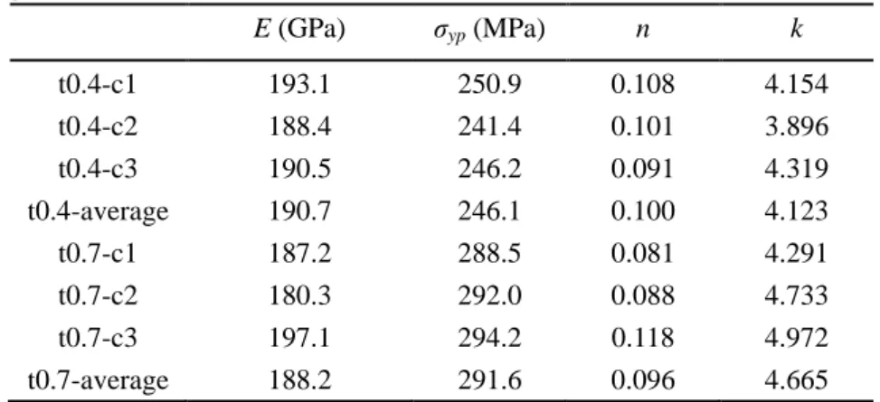
uniform external pressure, 𝑝𝑝0, see Fig.2-1. Let the pressure hull be made from Ti-6Al-4V(TC4), the material properties were as follows: Young modulus 𝐸𝐸 =110 GPa, yield strength 𝜎𝜎𝑦𝑦 = 830 MPa, tensile strength 𝜎𝜎𝑡𝑡 = 869.7 MPa, Poisson ratio μ = 0.3.
Fig.2-1 Geometry of a spherical pressure hull
[2]. Test details could be found in ref. [3]. In the test, the high-precision load cell and extensiometer were adopted, which could produce the exact engineering stress-strain curve, see Fig.2-2a. From this curve, tensile strength could be determined as the peak value of the nonlinear range, which was presented only for the evaluation of the material and not adopted in the following analysis.
(a) Experimental results (b) Regression results
Fig.2-2 Stress versus strain of Ti-6Al-4V(TC4)
According to this curve, true stress-strain relationship could be determined according to Eqs.(2-1, 2-2):
ln(1 ) true eng
ε = +ε (2-1)
(1 )
true eng eng
σ =σ +ε (2-2)
Its relationship between true stress and true strain could be defined as follows:
, for y σ Eε= σ σ< (2-3a) and 1 1 , for n y y y Eε σ σ n σ σ σ = − ≥ (2-3b)
parameter was regressed based the nonlinear range. The regression result was shown as elastic-plastic curve in Fig.2-2b. Also, the elastic-perfectly plastic curve was generated by assuming that the stress tended to be horizontal after the yield point. Both material curves were employed in the following analysis.
2.1.2 Buckling of geometrically perfect hulls
A total of 24 numerical analyses were performed for geometrically perfect spherical pressure hulls using the FE code ABAQUS 6.13. Half of them with 5 mm thickness increment were used for linear elastic buckling analysis, while others with the same thickness increment were adopted for geometrically and materially nonlinear analysis based on the arc length method. The fully integrated S4 shell element was employed to avoid hourglassing. The number of elements was determined using mesh convergence analysis in the case of linear elastic buckling analysis [4, 5]. It was noted that the different shell thickness might result in a different critical element number. Nevertheless, to keep the uniformity and simplify the problem, the maximum element number among shells with various wall thicknesses was employed in each model according to mesh convergence analysis of shells. This employment was due to fact that the buckling of a shell could vary slightly beyond the critical element number. As a result, each numerical model had the same shell elements of 6534 and the nodes of 8750. The uniform external pressure, 𝑝𝑝0 = 1 MPa was imposed on the whole surface of each spherical pressure hull. In this way, the eigenvalue obtained from linear elastic buckling analysis corresponded directly to the linear buckling load, while the arc length value obtained from geometrically and materially nonlinear analysis was the nonlinear buckling load. To avoid rigid body motion, three spatial points of each model are fixed according to CCS2013 [4], as follows: Uy=Uz=0, Ux=Uy=0,
Uy=Uz=0. These constraints did not lead to excessive constraint of the models,
because the pressure was applied uniformly.
(Eq.2-4), and Wang [7] for medium-thick-walled spherical shells (Eq.2-5):
(
)
2 2 2 3 1 t E t p r µ = − (2-4)(
2)
2 2 2 1 2 (1 ) 3 2 m t Et t t p r r r µ µ µ − − = − − (2-5)Table 2-1 Buckling loads of geometrically perfect spherical pressure hulls obtained from
numerical and analytical analysis, as well as their first yield analysis.
t/r pt pm-t Plin pe-p pfy pfy1
[MPa] 0.025 83.219 82.652 83.468 42.147 41.479 41.500 0.030 119.835 118.856 119.660 50.559 49.790 49.800 0.035 163.109 161.554 162.610 59.011 58.083 58.100 0.040 213.040 210.719 211.640 67.462 66.400 66.400 0.045 269.629 266.324 266.880 75.890 74.707 74.700 0.050 332.875 328.342 328.280 84.343 83.000 83.000 0.055 402.779 396.746 398.730 92.778 91.299 91.300 0.060 479.340 471.507 470.020 101.257 99.604 99.600 0.065 562.559 552.600 549.780 109.653 107.904 107.900 0.070 652.435 639.997 638.340 118.062 116.198 116.200 0.075 748.969 733.670 733.780 130.539 124.512 124.500 0.080 852.160 833.593 827.780 140.695 132.800 132.800 Notations: pt = buckling load obtained from the thin-walled equation; pm-t = buckling load obtained from medium-thick-walled equation; plin = buckling load obtained from linear elastic buckling analysis; pe-p = buckling load obtained from geometrically and materially nonlinear analysis; pfy = first yield pressure obtained from geometrically and materially nonlinear analysis; pfy1 = first yield pressure obtained from analytical analysis (Eq.2-6).
typical for highly symmetrical spherical shells [8]. As can be seen from Fig.2-3 (colors of buckling shape indicate eigenvector), the number of the wave crest decreased with an increase in the wall thickness. For instance, the number, n, of the wave crest is 11 for the 25 mm spherical pressure hull, while the number reduced to 6 for the 80 mm spherical pressure hull.
(a) t = 25 mm (b) t = 50 mm (c) t = 80 mm
Fig.2-3 Linear buckling modes of deep sea spherical pressure hulls with various wall thickness
The nonlinear buckling performances of a geometrically perfect spherical pressure hull were completely different from the linear one. As can be observed from Table 2-1, the nonlinear buckling load, 𝑝𝑝𝑒𝑒−𝑝𝑝, of each hull significantly decreased compared to the corresponding value obtained from linear elastic buckling analysis. This difference increased with an increase in the wall thickness. These findings suggested that material plasticity played a very important role in the buckling of deep sea pressure hull. The more sensitive to the plasticity the buckling load of a spherical pressure hull was, the thicker its wall thickness was.
these yield loads were obtained based on the median surface of the spherical pressure hulls. The yield load derived from the internal surface could be less than these values, because the maximum stress located at the internal surface for the medium-thick spherical pressure hulls under external pressure [10]. The first yield pressure of each spherical pressure hull was less than its nonlinear buckling load. These findings indicated that all of the spherical pressure hulls could buckle in the elastic-plastic range, which was consistent with previous studies regarding medium-thick shells subjected to external pressure [9, 11]. In addition, according to Eq.2-6, the analytical first yield pressure was listed in a separate column of Table 2-1.
1
2
y fyt
p
r
σ
=
(2-6)where 𝜎𝜎𝑦𝑦 = 830 MPa. As can be seen from the table, the numerical results were nearly the same as the analytical results.
(a) Perfect Geometry (b) Imperfect Geometry
Fig.2-4 Equilibrium paths of the 25 mm spherical pressure hull obtained from geometrically and
materially nonlinear analysis
identical with the equilibrium path of medium-thick and geometrically prefect conical shells under external pressure [12].
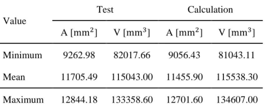
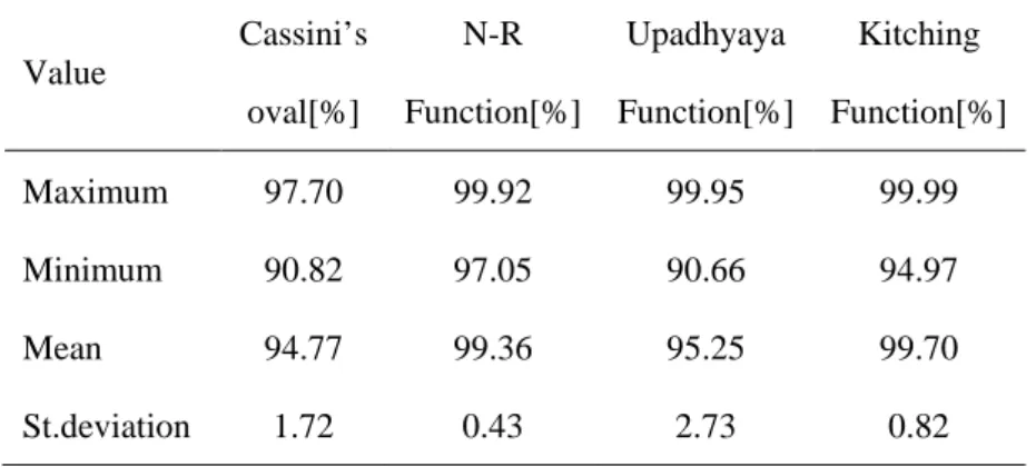
Table 2-2 Buckling loads [MPa] of spherical pressure hulls obtained from geometrically and
materially nonlinear analysis with eigenmode imperfections included; the parentheses show non-dimensional buckling load that is the ratio of each buckling load to the one in the case of t/r =
0.025 and δ = 2 mm, along with the ratios of the elastic-perfectly plastic buckling loads to the elastic-plastic ones, respectively.
t/r δ [mm] 2 4 6 8 10 0.025 35.465 (1.000,0.990) 30.265 (0.853,0.988) 26.268 (0.741,0.988) 23.180 (0.654,0.988) 20.777 (0.586,0.987) 0.030 45.149 (1.273,0.988) 39.714 (1.120,0.985) 35.191 (0.992,0.983) 31.500 (0.888,0.984) 28.486 (0.803,0.984) 0.035 55.698 (1.571,0.994) 52.183 (1.471,0.986) 48.402 (1.365,0.982) 44.857 (1.265,0.981) 41.658 (1.175,0.981) 0.040 64.578 (1.821,0.994) 61.308 (1.729,0.979) 57.795 (1.630,0.985) 54.250 (1.530,0.983) 50.933 (1.436,0.982) 0.045 73.765 (2.080,0.995) 71.282 (2.010,0.991) 68.642 (1.935,0.987) 65.846 (1.857,0.985) 62.985 (1.776,0.982) 0.050 82.246 (2.319,0.994) 79.553 (2.243,0.991) 76.689 (2.162,0.987) 73.654 (2.077,0.985) 70.524 (1.989,0.983) 0.055 90.567 (2.554,0.992) 87.458 (2.466,0.989) 84.150 (2.373,0.987) 80.683 (2.275,0.984) 77.007 (2.171,0.982) 0.060 99.925 (2.818,0.991) 97.378 (2.746,0.989) 94.662 (2.669,0.988) 91.833 (2.589,0.986) 88.920 (2.507,0.984) 0.065 108.865 (3.070,0.988) 106.243 (2.996,0.988) 103.468 (2.917,0.987) 100.579 (2.836,0.986) 97.620 (2.753,0.984) 0.070 118.037 (3.328,0.983) 115.623 (3.260,0.986) 113.046 (3.188,0.985) 110.358 (3.112,0.985) 107.599 (3.034,0.984) 0.075 128.165 (3.614,0.975) 125.374 (3.535,0.982) 123.041 (3.469,0.983) 120.781 (3.406,0.983) 118.482 (3.341,0.983) 0.080 136.857 (3.859,0.977) 135.021 (3.807,0.977) 132.653 (3.740,0.980) 130.433 (3.678,0.982) 128.263 (3.617,0.982)
2.1.3 Buckling of geometrically imperfect hulls
imperfection took the shape of the same linear buckling mode as that mentioned in Section 2.1.2, which may lead to conservative results [13]. The imperfection sizes were defined as 2 mm, 4 mm, 6 mm, 8 mm, and 10 mm, respectively. This imperfection assumption was in accordance with [14]. The mesh, load, boundary condition, and material specifications were the same as geometrically and materially nonlinear analysis. The modified Riks method was used to obtain solution due to the unstable problem. The calculating parameters were set as follows: initial increment in arc length along the static equilibrium path in scaled load-displacement space was set as 0.1; total arc length scale factor associated with this step is 200; Minimum arc length increment is 5E-5; Maximum arc length increment is 0.5; Maximum value of the load proportionality factor is 500. The obtained results are shown in Fig.2-4 and Table 2-2.
The critical buckling load, 𝑝𝑝𝑒𝑒−𝑝𝑝𝑙𝑙𝑖𝑖𝑝𝑝, of the spherical pressure hull decreased sharply with an increase in the imperfection size at the same wall thickness. For example, comparing Table 2-1 and Table 2-2, the critical buckling load of the 25 mm spherical pressure hull (35.465 MPa) is about 84% of that obtained from geometrically and materially nonlinear analysis at 2 mm imperfection size, and about 49% at 10 mm imperfection size. This decrease suggested that the spherical pressure hull was an imperfection sensitive structure, in which small shape deviations change its buckling load significantly. From Table 2-1 and Table 2-2, it is also inferred that sensitivity of imperfection to the buckling load of the spherical pressure hull decreased with an increase in its wall thickness. At the same imperfection size, the critical buckling load, 𝑝𝑝𝑒𝑒−𝑝𝑝𝑙𝑙𝑖𝑖𝑝𝑝, of the spherical pressure hull increased linearly with an increase in the wall thickness (Table 2-1), which was consistent with [14].
hulls initially exhibit a linear regime from the view of elastic mechanics, which is similar to the linear elastic shell analysis. Therefore, the deflection increases linearly with an increase in the applied load, which leads to the cusp. The deflection is measured on the maximum deflection point of shell, which is found at the end of the equilibrium path. Its critical buckling mode corresponding to the peak point was also listed in the same figure, as well as the post buckling mode corresponding to the end of the path. As can be seen, the critical buckling load of the pressure hull was similar to its linear buckling one; while the post buckling mode was in the form of a local dent, which was typical for shells of revolution with positive Gaussian curvature [11, 16]. Similar trends were found in other cases. Also, the first yield loads of these spherical pressure hulls were less than their critical buckling load, suggesting that all imperfect spherical pressure hulls buckled in the elastic-plastic range.
In addition, to examine the effect of constitutive models on the buckling spherical pressure hulls, another 60 numerical analyses were performed for the same imperfect spherical pressure hulls. All analyses were the same as the geometrically and materially nonlinear analysis with imperfections included mentioned in first paragraph of this section, except that the material properties were modeled as elastic-perfectly plastic. The parentheses in Table 2-2 detailed the ratio of the elastic- perfectly plastic buckling load, 𝑝𝑝𝑒𝑒−𝑝𝑝𝑝𝑝𝑙𝑙𝑖𝑖𝑝𝑝 , to the elastic-plastic buckling load, 𝑝𝑝𝑒𝑒−𝑝𝑝𝑙𝑙𝑖𝑖𝑝𝑝. This ratio varied from 0.975 to 0.995, indicating that the elastic-perfectly plastic could result in relatively conservative results. This finding extended previous works [9, 16], confirming that the elastic-perfectly plastic assumption could be used to predict the critical buckling load of shells of revolution subjected to uniform external pressure. This assumption were used to study the effect of yield strength on the buckling of spherical pressure hulls in the following sections.
2.2 Effect of yield strength on the buckling of hulls
material varied from 800 to 1300 MPa with an increment of 100 MPa. This range corresponded to the varying range of titanium alloys used to manufacture deep sea spherical pressure hulls [17]. The wall thickness of spherical pressure hulls ranged from 25 to 80 mm with an increment of 5mm. The other modelling parameters of this section were assumed to be the same as those of Section 2.1.1. According to the analysis results, a semi-analytical formula was put forward to evaluate the load carrying capacity of deep see spherical pressure hulls.
Fig.2-5 Plasticity reduction factor, 𝑘𝑘𝑝𝑝, versus the wall thickness-to-radius ratio, t/r, under six yield strengths, 𝜎𝜎𝑦𝑦
2.2.1 Perfect geometry analysis
reduction factor could be given by 0.986 0( ) p t k k r − = (2-7) 5 0 1.62 10 y k = × − σ (2-8)
These findings suggested that the nonlinear critical buckling load, 𝑝𝑝𝑙𝑙𝑛𝑛𝑙𝑙, of geometrically prefect spherical pressure hulls could be obtained from the product of the plastic reduction factor, 𝑘𝑘𝑝𝑝, and the linear buckling load, 𝑝𝑝𝑖𝑖−𝑡𝑡, obtained from the medium-thick-walled equation (Eq.2-5), as follows:
non p m t
p =k p − (2-9)
2.2.2 Imperfect geometry analysis
(a) 𝜎𝜎𝑦𝑦=800MPa (b) 𝜎𝜎𝑦𝑦=900MPa
(c) 𝜎𝜎𝑦𝑦=1000MPa (d) 𝜎𝜎𝑦𝑦=1100MPa
(e) 𝜎𝜎𝑦𝑦=1200MPa (f) 𝜎𝜎𝑦𝑦=1300MPa
Fig.2-6 Geometrical imperfection reduction factor, 𝑘𝑘𝑙𝑙𝑖𝑖𝑝𝑝, versus the wall thickness-to-radius ratio, t/r, under six yield strengths, 𝜎𝜎𝑦𝑦, and five imperfection sizes, δ
1 2 1 2 4 3 4 , , , (0.025 0.045) 0.045 , 0.055 , / 2, (0.045 0.055) , , , , , (0.055 0.0 y y y a y imp y y y y t t k k r r r r k k r r t k r k k r r t t t k k r r r r r δ δ σ σ δ δ σ σ δ δ σ σ δ δ σ σ + < < + = < < + + + < < 80) (2-10) where, 𝑘𝑘1�𝜎𝜎𝑦𝑦,𝛿𝛿 𝑟𝑟�, 𝑘𝑘2�𝜎𝜎𝑦𝑦, 𝛿𝛿 𝑟𝑟�, 𝑘𝑘3�𝜎𝜎𝑦𝑦, 𝛿𝛿 𝑟𝑟�, and 𝑘𝑘4�𝜎𝜎𝑦𝑦, 𝛿𝛿
𝑟𝑟� can be obtained from Fig.2-7. (a)𝑘𝑘1�𝜎𝜎𝑦𝑦,𝛿𝛿 𝑟𝑟� (b) 𝑘𝑘2�𝜎𝜎𝑦𝑦, 𝛿𝛿 𝑟𝑟� (c) 𝑘𝑘3�𝜎𝜎𝑦𝑦,𝛿𝛿 𝑟𝑟� (d) 𝑘𝑘4�𝜎𝜎𝑦𝑦, 𝛿𝛿 𝑟𝑟� Fig.2-7 Coefficients, 𝑘𝑘1�𝜎𝜎𝑦𝑦,𝛿𝛿 𝑟𝑟�, 𝑘𝑘2�𝜎𝜎𝑦𝑦, 𝛿𝛿 𝑟𝑟�, 𝑘𝑘3�𝜎𝜎𝑦𝑦, 𝛿𝛿 𝑟𝑟�, and 𝑘𝑘4�𝜎𝜎𝑦𝑦, 𝛿𝛿
𝑟𝑟�, of the equations versus
As can be seen from Fig.2-7, the coefficients,𝑘𝑘1�𝜎𝜎𝑦𝑦,𝛿𝛿
𝑟𝑟� and 𝑘𝑘2�𝜎𝜎𝑦𝑦, 𝛿𝛿
𝑟𝑟�, varied nonlinearly with the imperfection size and yield strength. We can obtain their values using the graphing method. On the other hand, the coefficients, 𝑘𝑘3�𝜎𝜎𝑦𝑦,𝛿𝛿
𝑟𝑟�, and 𝑘𝑘4�𝜎𝜎𝑦𝑦,𝛿𝛿𝑟𝑟�, varied linearly with the imperfection size and yield strength. Using the linear and nonlinear regression analysis based on Origin analysis software, these two coefficients can be given as:
(
)
3 y, 0.5087 y 11.231 k r r δ δ σ σ = + (2-11)(
)
4 y, 1 0.0447 y 3.2321 k r r δ δ σ σ = − + (2-12)As a result, in line with the generalized reduction factor approach (RFA) for shell buckling design [18], the load carrying capacity 𝑝𝑝𝑟𝑟𝑒𝑒𝑟𝑟𝑙𝑙 of deep sea pressure hulls could be determined from Eqs(2-5, 2-7~2-12), in the following semi-analytical formula:
real p imp m t
p =k k p − (2-13)
where, 𝑘𝑘𝑝𝑝 was determined from Eqs(2-7 and 2-8), 𝑘𝑘𝑙𝑙𝑖𝑖𝑝𝑝 was determined from Eqs(2-10~2-12) and Fig.2-7, 𝑝𝑝𝑖𝑖−𝑡𝑡 was determined from Eq.2-5.
Furthermore, an example containing full sequence of a step-by-step calculations using the semi-analytical formula for a typical case was provided, in the following:
Step 1: The geometry and material parameters of the spherical shell were as follows:
a spherical pressure hull was assumed that the median radius, r=1000 mm, uniform wall thickness t=30mm, the imperfection sizes δ=2mm. In addition, let the pressure hull be made from Ti-6Al-4V(TC4) with Young modulus 𝐸𝐸 =110 GPa, yield strength 𝜎𝜎𝑦𝑦 = 850MPa, and Poisson ratio 𝜈𝜈 = 0.3.
(
)
(
)
2 2 2 2 2 2 2 2 1 2 3 2 1 2 110000 30 (1 0.3 ) 30 0.3 30 118.856; 1000 (1 0.3 ) 3 1000 2 1000 m t Et t t p r r r ν ν ν − − = − − × × − × = × × − ≈ × − × Step 3: The plasticity reduction factor, 𝑘𝑘𝑝𝑝, could be calculated based on Eqs.2-7~2-8, this value was 0.437. The details were as follows:
0.986 0.986 0.986 5 5 0 30 1.62 10 1.62 10 850 0.437; 1000 p y t t k k r σ r − − − − − = = × = × × × ≈
Step 4: The geometrical imperfection reduction factor, 𝑘𝑘𝑙𝑙𝑖𝑖𝑝𝑝, could be acquired by first segment function of Eq.2-10 due to t/r = 0.03. The coefficients,𝑘𝑘1�𝜎𝜎𝑦𝑦,𝛿𝛿
𝑟𝑟� and 𝑘𝑘2�𝜎𝜎𝑦𝑦,𝛿𝛿𝑟𝑟�, varied nonlinearly with the imperfection size and yield strength. One could obtain their values using the graphing method from Fig.2-7. Therefore, the value of 𝑘𝑘𝑙𝑙𝑖𝑖𝑝𝑝 was 0.8766 based on Eq.2-10. The details were summarized as follows:
(1) when δ/r = 0.002 and 𝜎𝜎𝑦𝑦 = 800 MPa, the corresponding values of 𝑘𝑘1�𝜎𝜎𝑦𝑦,𝛿𝛿 𝑟𝑟� and 𝑘𝑘2�𝜎𝜎𝑦𝑦,𝛿𝛿
𝑟𝑟� were 6.430 and 0.694; when δ/r = 0.002 and 𝜎𝜎𝑦𝑦 = 900 MPa, the corresponding values of 𝑘𝑘1�𝜎𝜎𝑦𝑦,𝛿𝛿
𝑟𝑟� and 𝑘𝑘2�𝜎𝜎𝑦𝑦, 𝛿𝛿
𝑟𝑟� were 7.610 and 0.638. (2) The yield strength (𝜎𝜎𝑦𝑦 = 850 MPa) was between 800 MPa and 900 MPa, the
final values were obtained by the linear interpolation, as follows:
(
)
1 50 , 7.610 6.430 6.430 7.02; 100 y k r δ σ = × − + = (
)
2 50 , 0.694 0.638 0.638 0.666; 100 y k r δ σ = × − + = (3) The value of 𝑘𝑘𝑙𝑙𝑖𝑖𝑝𝑝 was calculated, as follows:
1 2 30 , , 7.02 0.666 0.8766 1000 imp y y t k k k r r r δ δ σ σ = + = × + =
118.856 0.437 0.8766 45.531 real p imp m t
p =k k p − = × × =
This semi-analytical formula included the medium-thick-walled analytical buckling equation to determine the linear elastic buckling load of deep sea spherical pressure hulls, along with the quantitative evaluation of reduction of this load due to the nonlinearity of material and the shape deviation of geometry. The formula involved most of the geometrical, material, and manufacturing parameters that affected the buckling of deep sea spherical pressure hulls, such as the ratio of wall thickness, r, to radius, t, the conservative imperfection size, δ, Young modulus, 𝐸𝐸, yield strength, 𝜎𝜎𝑦𝑦, and Poisson ratio, 𝜈𝜈 . The interrelationship and interaction among these parameters were considered by defining the plasticity reduction factor as a function of the yield strength and the wall thickness-radius-ratio, and by defining the plastic imperfection factors as a function of the imperfection size-to-radius-ratio, the yield strength, and the wall thickness-radius-ratio. Most importantly, this formula was a kind of mechanism model corresponding to the buckling regime of deep sea spherical pressure hulls.
was not associated with the buckling regime of deep sea spherical pressure hulls, although the empirical formula could accurately evaluate the load carrying capacity of deep sea spherical pressure hulls in some cases. In other cases, for example, if Young modulus, 𝐸𝐸, yield strength, 𝜎𝜎𝑦𝑦, or Poisson ratio, 𝜈𝜈 changes, this empirical formula could not adapt to these variations and may give an incorrect result. Therefore, this empirical formula was a kind of phenomenological model, which could be considered as the special case of the current work. Our proposed semi-analytical formula extended previous work and could be used to evaluate the load carrying capacity of deep sea spherical pressure hulls at preliminary design stage.
(1 )( t t ) real in in p k t t r r m σ σ δ = − + (2-14) 2 3 3 2 exp( ( ) ) in in in in in in t t t k a b c d j f g h r r r r r r δ δ δ = + ⋅ − − + + − − (2-15)
where, 𝑟𝑟𝑙𝑙𝑙𝑙= internal radius; 𝛿𝛿=imperfection size; 𝑟𝑟𝑖𝑖= mean radius; 𝜎𝜎𝑡𝑡= ultimate strength; 𝑡𝑡 =wall thickness; a, b, c, d, j, f, g, and h are constants.
2.3 Experimental methodology of spherical shells
This section involved sampling and analyzing 10 spherical shells to determine their buckling behaviors. A series of tests were performed to obtain the geometrical and buckling properties of these shells in addition to their material properties.
2.3.1 Shell manufacturing and testing
during the manufacturing process because the ratios of the wall thickness to the nominal diameter were very low. Before the spherical shells were tested, the wall thickness and geometric shape were measured for all the shells.
(a) Measurement site (b) Points distribution
Fig.2-8 Measurement site and typical distribution of testing points for wall thickness
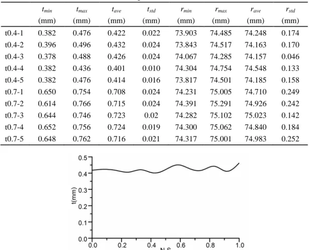
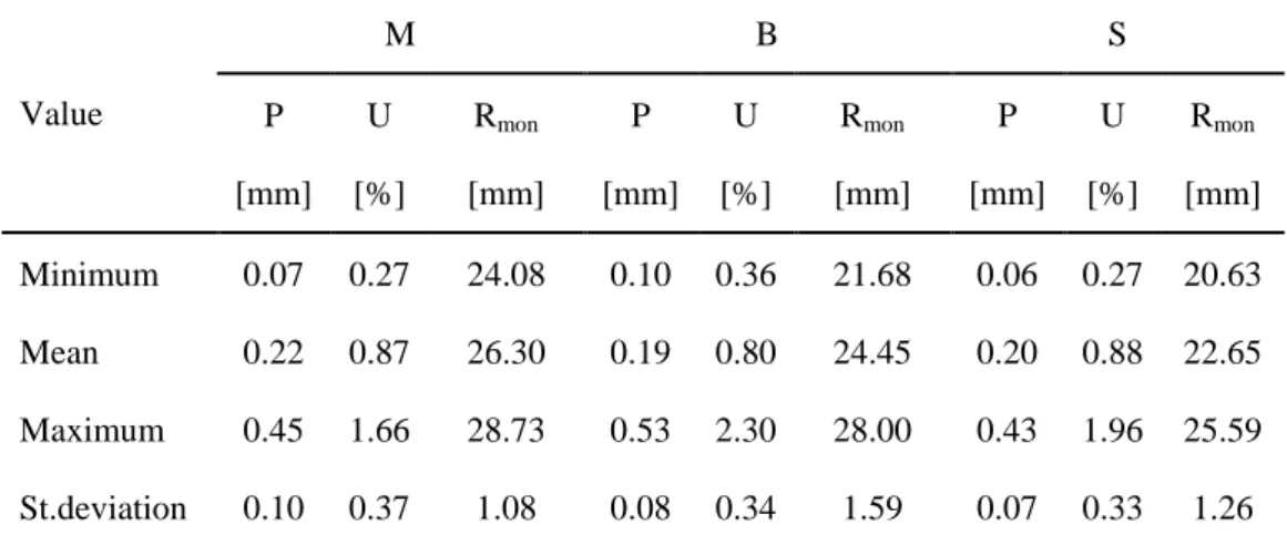
First, the thickness of each wall was measured using an ultrasonic probe at 13 equidistant points along a meridian for eight equally spaced meridians, as detailed in Fig.2-8. Each shell was measured at 8 ×11 + 2 = 90 points. The values of the minimum (tmin), maximum (tmax), and average wall thicknesses (tave), as well as the
corresponding standard deviations (tstd), are listed in Table 2-3. Overall average wall
thickness profile from the North-Pole to the South Pole for a t0.4-1 spherical shell and its thicknesses of all measure points are also showed in Fig.2-9 and Table 2-4 respectively. The average variation between the maximal and minimal wall thicknesses was approximately 17%, which may be attributed to the stamping process. Second, the geometries of all the spherical shells were obtained using a three-dimensional optical scanner, developed by Open Technologies Corporation. The scanned accuracy is not more than 0.02 mm reffering to operating manual provided by the corporation. Each shell surface was scanned in the form of a point cloud and automatically transformed into a CAD model. Each model demonstrated the real geometric shape of the corresponding shell, which contained deterministic geometric imperfections caused by manufacturing processes. Furthermore, the minimum (rmin),
maximum (rmax), and average radii (rave) of each shell were also obtained from the
CAD model in addition to the corresponding standard deviations (rstd); these values
curvature for a t0.4-1 spherical shell are presented in Fig.2-10.
Table 2-3 Testing values of the wall thickness and radius for spherical shells (minimum,
maximum, average, and standard deviation). tmin (mm) tmax (mm) tave (mm) tstd (mm) rmin (mm) rmax (mm) rave (mm) rstd (mm) t0.4-1 0.382 0.476 0.422 0.022 73.903 74.485 74.248 0.174 t0.4-2 0.396 0.496 0.432 0.024 73.843 74.517 74.163 0.170 t0.4-3 0.378 0.488 0.426 0.024 74.067 74.285 74.157 0.046 t0.4-4 0.382 0.436 0.401 0.010 74.304 74.754 74.548 0.133 t0.4-5 0.382 0.476 0.414 0.016 73.817 74.501 74.185 0.158 t0.7-1 0.650 0.754 0.708 0.024 74.231 75.005 74.710 0.249 t0.7-2 0.614 0.766 0.715 0.024 74.391 75.291 74.926 0.242 t0.7-3 0.644 0.746 0.723 0.02 74.282 75.102 75.023 0.142 t0.7-4 0.652 0.756 0.724 0.019 74.300 75.062 74.840 0.184 t0.7-5 0.648 0.762 0.716 0.021 74.317 75.001 74.983 0.252
Fig.2-9 Overall average wall thickness profile from the North-Pole to the South Pole for a t0.4-1
spherical shell
Table 2-4 Thickness (mm) at 13 equidistant points along 8 meridians for a t0.4-1 spherical shell.
![Table 2-2 Buckling loads [MPa] of spherical pressure hulls obtained from geometrically and materially nonlinear analysis with eigenmode imperfections included; the parentheses show non-dimensional buckling load that is the ratio of each buckling load to](https://thumb-ap.123doks.com/thumbv2/123deta/10124450.1958420/36.892.154.746.316.930/buckling-spherical-geometrically-materially-nonlinear-imperfections-parentheses-dimensional.webp)