イオン結晶の成長組織及び塑性変形組織に関するX線的研究
21
0
0
全文
(2) Vol. 4, No. 2 Journal of Hokkaido Gakugei University CSecl;. B) - July, 1953...?^ •'.••>••'". STUDIES ON THE GROWN AND DEFORMED . STRUCTURE OF SOME IONIC- CRYSTALS * • IVTasaaki Yanagisawa - ;. Laboratory of Chemistry, Asahikawa Branch, . Hokkaido Gakugei University - / ~. tWTEBg: ^^-^^^o^[email protected]^^®Kfca-rsx^6^% -^:^ SYNOPSIS. .. •. .^i. -.'-^M. The grown and deformed structure of some ionlc crystals have been investigated by X-ray, . .. -''.I. ^"•- ^^. and it was found that in some crystals worb-hardening and recrystallization phenomena existed, . ^^. and some trials to produce single crystal and to discriminate the grain-have been performed. • ''^. I. INTRODUCTION • ^ ".<s. Oriented structure in which micro crystal grains assume a definite orientation with respect to a corn- ~ .^S mon direction—that of worldng or growth, results from the plastic deformation and crystal growth; ' ^ Many studies have been reported as for the oriented structure by growth of metaJs and alloys -.^ in the case of cast texture1) i. e. growth to solid from liquid phase, of electro-deposited texture,2? • ^ of deposited structure of metals from solution by displacement,3) and of recrystallization texture*) '. ^ i. e. growth to solid from solid phase. Furthermore, the oriented structure by plastic deformation in the case of rolling, drawing, forging, compression, torsion and etc., have been studied. . .. But as it has not yet been known if plastic deformation or growth of ionic crystal produce. -.^. the oriented structure, in this studies, the cast texture of some ionic crystal as the structure of ; -^]. • ~fy^. growth to solid from liquid phase, the recrystallization texture as the structure of growth to solid ..:- ^ from solid, and the texture of rolling as the structure of plastic deformation have been subjected ^. to the X-ray, mechanical and other investigations. . . -^. "^. This studies have been carried out ou the crystals of rock-salt, cesium chloride and zincblende . »•?; type. lattice.. .. -. -. '-:. .^. It has been also subjected that some of these crystals had recrystallization and work-hardeniyg ' ?f| '•v.^. phenomena, and stress-annealing method was appUed to produce single crystals and several - \'^' discrimination method of grains were attempted for silver chloride crystals. ^ ^. II. PREPARATION OF SPECIMENS. ^. ,--. ^. Specimens used in this experiments are sodium chloride, potassium chloride, potassium bromide; . ::g potassium iodidp, silver chloride, and silver bromide, which belong to the lattice of rock-salt -;;; *"-. type, cuprous chloride aud cuprous bromide belong tn the ziricblende type, aud thallinm chroride, •. ~ g * Doctor thesis (Hokkaido University). — 25 —.
(3) Maaaaki Yanagisawa. thallium bromide and thallium iodide belong to the cesium chloride type. Alkali halides were purified by the recrystallization from their water solution, and melted. Silver chloride were prepared as follo>v ; silver nitrate dissolved in distillated water was treated with a little excess 12N. hydro-chloric acid, and precipitated powder-lilse silver chloride was washed fully with water, dried at 105 "C in electric dryer, melted in porcelein crucible and then cast in another crucibls. Silver chloride varied its colour from white to yellow with promoting the temperature and melt to brown liquid. With cooling the silver chloride, the colour varied inverse process and finally cast ingot had become semitransparent and it gave metallic sound when knocked. Silver bromide was prepared from silver nitrate, and ammonium bromide. Drying, melting and casting were performed in the same manner as silver chloride. Cast ingot thus obtained was semi-transparent yellow and gave also metallic sound. Silver chloride or broroidc can prepare from silver nitrate, treating with sodium chloride or potassium bromide instead of using hydroohloric acid or ammonium bromide. But the specimen thus obtained had little plasticity as would be described later. Cuprous chloride was prepared as follow ; after green colour of cupric carbonate solution • to which 12N. hydrocHoricacid and metallic copper were added had diminished by heating, white powder of cuprous chlorido precipitated when this solution was poured into a plenty of water. .To avoid the oxidation, this precipitates were washed with alcohol aud ether after washed with water, and melted in a porcelcia crucible under low pressure. -. Upper part of this ingot was composed of slag-like black substance which was probably cupnc oxide and could easily peeled off from white cast cnprous chloride ingot. 'Cuprous bromide was prepared from cnpric carbouate, ammonium bromide and metallic copper, and drying, melting and casting were performed in the same manner as cuprous chloride. Thallium chloride or bromide was prepared from thallium nitrate and hydrochloric acid, ammoniurn bromide and thallium iodide manufactured by British Drug Go. was used in this experiment.. These compounrls were heated iu porcelein crucible respectively at 50° C high above their melting point and cast in another preheated crucible, but cuprous chloride and bromide \vere cooled in the furnace. In the case of furnace coiling of alkali hfilides, dendrites grown perpendicular to the wall of crucible have not been observed, but single crystals of which dimension was about l~3m.m edge have grown. So, to obtain the dendritic crystals, casting in another crucible had to be applied. As for silver amd thallium halides, dendritic crystals grew either by casting or cooling in furnace, and by the former method ingot could be easily separated from the crucible. At the brofeen face of ingot of which climension is about 20m.m. in diameter and 15m.m. in length, the dendritic crystal whose length is shown in Table 1. had been observed near the wall, on the other hand, innerpart of ingot.was composed of random aggregates of micro crystal grains. Silver chlorule, brnmide, cuprous chloride and bromide had showed the remarfeable flencfritic growth.. — 26 —.
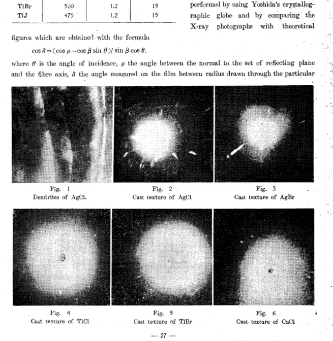
(4) '": ~w. 'i. Studies on the Grown and Deformed Structure of Borne lonic Crystals Table. specimen. casting tem peratnre. (°C). mean length of dendrites (m.mO. I. .. :->^. ;~. III. DETERMINATION OF;'. •ooling velocity. CAST STRUCTURE .BY. melting point. X-RAY LAUE METHOD.. (°C/min). 1.6. 15. KC1. 855 820. 1.5. 15. KBr. 770. 1.5. 730. 1.4. 17. the primary X-ray beam wliirh was. 510. 3.0. emitted from copper target, the diffrac-". AgBr. 480. 3.0. 20 20. CuCl. 470. 2.8. 3.5. CuBr. 540. 2.5. .3.5. T1G1. 480. 1.2. TlBr. 50U. 1.2. T1J. 475. 1.2. NaCI. KJ AgGl. 15. 15 15 15. When these dendrites were placed perpendicular or at an oblique augle to. tion rings were inteusive in localizeki parts.. The analysis of 'orientation can be perfurmed by using Yoshida's crystallog-. raphic globe and by comparing fbs X-ray photographs -with theoretical. figures which are obtaiuei'. with the formula cos 8 = (cos p— cos 0 sin 0)1 sin ft cos 0. where 0 is the angle of incidence, p the angle between the normal to the set of reflecting plane and the fibre axis, 8 the angle measured on the film between radius drawn through the particular. Fig. 1. Fig. 2. Fig. 3. Dend rites of AgCl.. Cast texture of AgCl. Cast texture of AgBr. Fig. 4. Fig. 5. Pig. 6. Cast texture of T1C1. Cast texture of TlBr. Cast- texture of CuCl. —27 —.
(5) Masaaki Yanagisawa. f'"w&Cast texture"ofTCuBF. Fig. 10 Cast texture of KBr. Fig. 8. Fig. 9. Cast texture of CuBr.. Cast texture of NaCl. Fig. 11. Fig. 12. Cast texture of EC1. Cast texture of KI. mten^maxima and the verticalline, aud 0 the angle between the fibre axis and the direction nf primaly X-ray beam, aud ^ is 90° or 45° in this experiment. By analysis as stated above, orientation of these dendrites have C 112:1 fibre axis paraUel to the directious of growth as indicated' in Table II. As lattice plane which have large growth. Table ][. velocity is covered and put out of sight by the lattice plaue which have small growth velocity, and, thus observable crystal plane may be the. specimen. plaue of which growth velocity is relatively small,. NaCl. and direction of growth corresponds to that of. KC1. fibre axis normal to the plane which have large growth velocity. When alkali-halides were prepared not by casting but by furnace cooliug, crystals growu. KBr. KJ. crystal lattice. projecting angle. c/o. ^90°. ditto. C1123. 90°. Cii2] C112] [112]. ditto. 9.0°. AgCl. ditto. 90°. .ditto. 90° & 45°. AgBr. ditto. C 1.12]. 90°. [112] CII23. CuCl. ZnS type. 90°. CuBr. (100), rarely (110) plane, and Alkali halides. T1C1. ditto. 90°. CsCl type. 90° & 45°. C 100) plane and so rarely have (110) or (111) - 28 -. CBkl]. NaCl type. near by wall were single crystals iuclosed by. .grown from these water solution had also generally. fibre axis. TlBr. TU. ditto. 90° & 45°. ditto. 90° & 45°. C 1123. , .C112]. [112]. '[1123..
(6) Studies on the Grown and Deformed Structure of 8ome lonic Crystals '.. plane that they were called abnormal plane. ^. which had come out when inorgamc,.:}eii[ such as stannous, cadmous, bismuth, a.ud. titauium ion or organic substance suc^ as urea exist.5). "•-• -syy. The fact above described iudicate that./in' these ionic crystals growth velocity jaf (,1'@Q). plane, and rarely (111) or Cl 10) is relatrvely: smaU.. -. .. .,. ."•-. This agree with that dendrites have Cll^J fibre axis.. IV. PLASTIC DEFORMATION- OF IONIC CRYSTALS. Many studies have been carried on fee'. Fig. 13 few. on. iouic. plastic deformation of metals and alloys 'but crystals.. '. .. .. .. '. .. m. ~-'. Stepanov6) reported, that some silver-halide cau draw out. The ingot of silver chloride and bromide prepared as described above could be bent and deformed by fingers and it could be realised that such crystals had relatively large plasticity. It seemed that ingot of another ionic crystal had not plasticity, but thallium chloride, bromide and iodide had plasticity by rolling as would be described later. It is interesting to investigate whether these iouic crystal have fiber structure or riot by. -n. /^ r;I. <^. •Si. •^. working.. Working had been carried out by the hand-drivuigi two steps roller of which diameter is 30m.m; Results obtained are as follow : ( 1 ) Both silver chloride and bromide have so plasticity in such a degree enough to be rolled, but silver chloride is easier to be rolled than bromide. In regards to silver chloride, rolling can be performed easier wheu this ingot was heated above about 60°C. The fact that both crystals give out slip sound when rolled or beut, as well as tin gives out so-called "Tin cry" when tiu was plastically deformed, suggests the occurance of slip of lattice plane with working. Both crystals can be easily rolled from 5 to 0.02m.m. in thiclmess by several times rolling without cracks, and as a matter of fact, be rolled to 1~3^ foil by further rolling.. ( 2 ) Albali halides, cuprous chloride and bromide have so little plasticity that they . crumble by rolling. Although these specimens were heated to 200°C, they had not so plasticity as can be rolled.. ~-::iM. ?a '."a ~. .•:». ^ 'uf. ^. ,--1. ^* In .-•1. ( 3 ) Thallium chloride, bromide and iodide can be rolled to thin foil, though cracks apt .to come out.. ( 4 ) Silver iodide from silver nitrate and excess hydrogen iodide have not plasticity but from " excess silver nitrate and hydrogen iodide at low tempertute (2 °C) can be rolled to thin plate. . -. 29. —. f! ;'<. • /-*•.
(7) Masaaki Yauaglsawa. (5 ) Silver chloride aud bromide prepared from silver nitrate with sodinm chloride or potassium bromide cau not be rolled easily aud have poor plasticity, but these Sjiecimes which have been washed a number of times with water have come to preserve plasticit}'. Kelation between plasticity and the number of washing- is shown m Table III where water used for washing is 150c.c. per one time per 25gr. of precipitates. As for silver chloride, same relation. Table ffl. exists and specimeu washed thirty times. Washing. can be rolled to thiu plate though cracks. Eoll cjack. times. apt to come out.. 3. This is probably due to the small. 10. amount of reaction product sodium uitrate or potassium uitrate which yet have left over iu the little even by. very remarkable remarkable. 15. less remarkabl, but can be made to foil. 20 30. slightly roll crack, but can be made to foil the same as above. washing aud have remaind while melting and prevented the occurance of slip when working. On the other hand, reaction product ammonium nitrate or mtric acid which have come from silver nitrate and hydrochloric acid or ammouiiim bromkle escape while melting and probably do not prevent the slip, when working is held ou.. V. WORK-HARDEN1NG OF SOME IONIG CRYSTALS. Such irreversible defbrmation as plastic deformatiou causes worb-hardening except the occurance of twin deformation. As described above, silver chloride, and sume ionic crystal have plasticity, therefore it is expected that phenomenon of work hardening exists in such crystal. Alternatiou of hardncss accompanied by rolliug have beeu measured by Shore scleroscope on silver chlorule and bromide plate, but the experiments have uot been perfdimed ou thallium Kalides because of their crack which had preveuttid the mt'asurement of hardness. The value /. of harduess adopted is the mean value of measurements of twenty times.. The hanlness of cast state is shown in Table IV. where upper part mean the surfuce which is. Table IV. No7r. -No.. 2. AgCl. Mean hardness. No.3 No. 4 No75. -AgBr. No. 1 ^o72-No7y No; 4. Upper sarface. 12.4. II..7. 12.0. 12.3 12.3. 11.5. 11.6 11.3. 11.3. Under surface. 12.0. 11..4. 11.6. 11.0 11.9. 11.0. 11.5 9.7s. 11.1. Total mean hard ness 11 -So. 10.8,. in contact with air and the under part in contact with the base of crucible, Hardm'ss is higher in upper surface and mean value of upper aud luuler surface is 11.8 for silver chloritlc and 10.9 fur silver bromide. It had been found by Goldschmidt that in sodium halide crystals which belonged to the lattice of rock-salt type, Moh's hardness elevated in regular order of iodlde, bromide, chloride and fluoride, and that the more decreased the ion distance, the more increased the hardness. 0. '. 0. •. As the iou distauce, is 2.88 A iu silver chloride ami 2.77 A in silver bromide, the result. - 30 —.
(8) -',[^ ^'. Studies on the Grown and Deformed Structure of Some lonic Crystals. Table V "AgCT No. 1. Eednction. C%). Hardnes!. "AgCT So. 1. Eediiction. C%0. Hardness. AgBr:. Reduction. W). No. 2 .. HardneaS.. 0. 11.2s. 13.3. 13.0. 20. 8. 47.7. 13.6. 18.5. 12.8. 52.7. 14.0. 13.5. I3.I6. 34.8. 14.1. 33.4. 13.0g. 61. 15.7s. 23 ,. 13.5. 15.1. 39. 13.2. 69.5. 14.1. 38.5. 13.4. 13.3. 13.7s. 13.5. 13.1. 52 58. 13.0. 67.5. 15.4. 75 92. 12.2. 3.6. 14.0. 9.2-. 15.1. (%). NoTT. 12.1s. 0. • 19.3. "AgBr; Eeductioi. 11.8. 12.2. 67 73. AgCl. So. 3. Eeductiou Hardnesi (.%'). 0. 0. 31. HardnesE 11.5r,. 18.4. 41.6. 79 85. 16.2. 50. 15.0. 44. 14.8. 58.5. 16.9. 53.3. 13.3. 80 91. 92. 12.9. 16.2.,. 92. 66 70 72. 18.3. 68. 20.8. 73. 12.9. 18.0. 80. 13.0. 87. 13.5. 92. 14.2. 0. 3.8,,. 10.-5. 12,4s. 15.5. 12.4. obtained agree with the interpreta-. tion by Goldschmidt. For silver chloride altemation of hardness by working is shown in. Table V and Fig. 14 iu which the reduction percent of rolling -y/as defined by the relation reduction '/a = (d—d/)/d X 100 where d was the thickness of the plate 4.0. before rolling and d/ after rolling.. o0. Reiluction '/<. The harduess of silver chloride. Fig. 14. increases with the rate of reductions aud has a maximum point at about 1Q°/a and decends as reduction proceeds. When thickness of foil readied to 0.1 m.m. the hardness. measured were influenced by the under ground, so the measurments. were performed to the thickness above 0.25m.m.. For silver bromide hardness increased with the rate of reduction 40 60. 80. Reduction^. and had a maximum point at 60%. The results obtained are shown in. Fig. 15. Table V and Fig. 15.. — 31 —.
(9) Masaaki Yanagisawa. VI.. HARDNE8S ALTERNATION OF ROLLED SILVER CHLORIDE AND SILVER BROMIDE PIATE BY HEA.T-TREATMENT.. As would be described later, thje rolled silver chloride and bromide plate have fibre structure. and the recrystallization phenomenon by heat-treatment, therefore, it is'expected that these plate show the hardness alternation with annealing. On silver chlonde plate specimen No. 3 of which reduction is 75%, annealing was performed 1~2 hour at 100°, 200° and 300°C. The results obtaineil are shown in Table VI and Fig. 16. '. Table V[. A2C1 x 100'C annealing. ^.nnealing. temp.. Annealing. 0 200°c anneaj.ng. 100°C. 100°C. 200°C. 300°C. 0 2. 12.9. 12.9. 12.9. 12.9. 5. 11.6s. time (mm.). 12.0. 10. 15 20 25. 17.0. 12.6.,. 12.4s. 12.8. 12.0s. 13.0s. 35. 40 45 50 55. 12.1s 12.6. 12.0. 12.0s. 11 (m in.). Fig. 16 11.9. ~. 12.5 12.3. 12.0. o 3<*o"C an-neal.n.^. 12. 120. 12.5. x 100°C annealing. 13ff.•^v--^—«.,,. 12.2;. 60 80 115. 11.8. 12.9. 30. }". 12.0 11.85. 12.3a 12.5. d 13. 12.0. Wheu annealed at 100 °C, hardness fell with the time and then rose to the larger value. 12.7. compared with the hardness before annealing and -. 12.0. again fell with the progress of anneaUng and tended to constant value. .. The fact that the hardness elevates in pure substance, have been found in metals and have been investigated from the point of view with disslocation theory. For example, Tshida and Yasumori7) found abnormal hardening in Alminium and concluded that the hardness falling at the beginning of annealing was caused by disapearance of disslocation i. e. cancellation of positive and negative disslocations, and the succesive rising by appearance of subgrain which came out from the movement of same sign disslocations and the next falling came out from crystal growth. When aunealed 200°C, hardness have elevated to maximum in 20 min., but this maximum has been lower then the one before annealing and when annealed at 300° G hardness have fallen with the time and tended to constant value. That abnormal hardening have not been observed at 200° C and 300 °C depends on the recrystallization which begins rapidly at relatively high temperature and agrees with the result by X-ray investigation that recrystallization Lane spots have come out after 120 min at 100°C anuealmg but after 3 min. at 150°C, -32.
(10) :-@1. Studies on the Grown and. Deformed Stracture; of Some Tonic Crystals. -•^. For silver bromide plate No. 1 of which reduction is (A°/o and initial hardngss is 15.75, by keeping this plate at room temperature for 5 days, the hardness have fallen to 11.7 and further aunealing have made to elevate the hardness in 2 mm, and to show the maximum and have. :8 "-^. -^. ...3. fallen to constant value.. Table Anaealing time (inin.). IOO°C 11.7. 2. 13.0.. 5. hardening has been caught at 100 °C but not at 200°C. 100°C -15.5. 15-5. 14.1. 13.1. 15.3. 12.3. 16.8. 12.2. 200° C annealing. Results obtained are shown in. 13.5. 20 25 30 35. 12.5 12.2. 12.4. 40. 12.1. 12.1. I. '-i A^i. 58% RenLuct.un. 61% P.e(l,ut,»n. 15. ;;^ ..^,. Table VII and Fig. 17.. • 13.0. 10. ;<i. reduction is 58% and hardness is 15.5, abnormal;. Annealing temp. 0. 8. For another silver bromide plate No. 2 of which. VI. ICO'C an.ned.l-nfl. 10o°c ATincal.Ti^. ZOO'ia anneiil.ng. 12.3 12.1. 45. 30 40 (Trun;). 12.2.. 60. 20 30 40 50 60 (•mift.). Fig. 17. 12.1. VI. DETERMINATION OF DEFORMED TEXTURE. ^. BY X-EAY INVESTIGATION. A s described above silver chloride, bromide, thallium chloride, bromide and iodide have .had so plasticity that could be rolled to foil and gave out the sound as "Tin-cry", it has been expected that these foil had the structure in which micro crystal grains arranged in special axis parallelto the direction of rolling. Applying the X-ray Laue method emitted by copper target, photograph showed that the discoutenious intensity maxima in the Debye-ring diffracted by the characteristic X-ray aud radiation baud diffracted by white X-ray The analysis of these photographs have been performed by the Yoshida's crystallograpliic globe and the theoretical figure. Results obtaineil are as follow : .silver chloride foil of which rediu'tion is 98^ has showed intensity maxima existed ou the (111) and (^200) Dcby ring, and. 18. of which reduction is 96 and 98.2 °/y intensity maxima in. AgClCllO^fibre structure of Which. Deby-ring and radiation baud. Analysing these photograpb, it found that these foil had the fibre structure of which axis was C 110] parallel to the direction of rolling. Silver bromide foi-ls have showed the same maxima — 33 -. rednctiou is W% and of -which axis is parallel to the direction of rolling, showing the intensity ma.x-. imiim in (HI) and <ZOOj Debye rings diflTracted by the characteristic X-rays.. ,.t.
(11) M'asaaki. Yanagisawa.. C'[°3-V\'\. + ''('[in). Fig. 20 The same structure of which. Fig.. 19. reduction, is 96% showing the radiation band diffrac-ted by the white X-rays.. Fig. 21 AgBr[ 110]fibre structure of. which reduction is 98.5 %, showing the intensity max-. imum inC 111) and(200) Debye rings difFracted by the characteristic X-rays.. 22. Fig. 23. AgBr C 110] fibre structure of which reduction is 98 %, showing theC I lO^axis is parallel to the direction of rollng.. Texture of rolled T1C1 foil. Fig. .24. Texture of TlBr rolled foil. of which axis is C 100] parallel. showing the [100] fibre s-. to the direction of rolling.. tructure.'. as silver chloride foil and had the fibre structure of which axis was C110J. As for thallium chloride, bromide and iodide which belong to cesium chloride'tyjie, it has been fouml that these foil had fibre structure of which axis was C 1003 by analysing the X-ray photograph.. VII. DETERMINATION OF RECRYSTALLIZATION TEXTURE BY- X-RAY INVESTIGATION. Worked metals and alloys, in aeneral, recrystalize by heat-treatment and the recrystallization structure with regards to the aggregates of micro crystal, are olassified to , ( 1 ) aggregates of random arrangement.9) ( 2 ) aggregates of another fibre structure different from the initial fibre structure.8) ( 3 ) aggregates of identical fibre structure with initial one.1") X-ray Laue method has been applied to silver chloride rolled plate to investigate the. - 34 —.
(12) ^ '.m. Studies on the Grown and Deformed Structure of. Some Tonic Crystals recrystallization aud its structure and the results obtained are as follow. . - , .. 100 "C 30 mill. annealing : there have been no changes compared with the photograph of the original rolled foil and recrystallizatiou have not yet beeu begau. 100 °C. 60 miu nunealing : ditto 100°C. 120 mill anncaliug : Lane spots by the srowth of micro crystal grams, have come out departing from the original fibre axis Cl KD and - recrystallization has been begginiug. 100"C 240 min. arinealiug : photographs have showed the Laue spots by recrystalliziition,and the Cl KTl fibre structure which liave rcsiducd 125°C. 10 min. aimealing-: no changes have not been. observed and' reurystallization have not yet been began • 125 °C. 15 min. aunealiug : ditto. Fig. 25. 125°C. 30 min. annealing : recrystallizatiou haveproceeded comparatively but original fiber structure which. Fig. 26 AgCl foil annsaled at 100°C. Laue spots have camming out.. 240 inin.. Fig. 28 AgCl foil anaealed at 100°0 180 min.. Fig. 30. Fig. 29 AgCl foil annealed at 100°C. 30 min.. Fig.. AgCl foil annealed at 100°C. 120 min. Recrystallizatiou. 60 rain.. AgCl foil annexed at 100°C '. AgCl foil annealed at 120°C 10 niin.. Fig. 31 AgCl foil annealed at 1 25°C 15 ruin.. 35 —. •'^.
(13) Masaald Yanagisawa. Fig. 32. Fig. 33. AgCI foil annealed at I25-C. 30 inia.. Ag.Cl foil annealed at I50'C 3 min.. Fig. 35. Fig. 34 AgCl foil annealed at 150°C 6 inin.. Fig. 36. AgCl foil annealed at I50aC 10 juin.. AgCl foil annealed at 150°C 30 min.. FJg-. 38. Kg-. Pig. 37 AgCl foil annealed at 200°C 30 min.. 39. ^. ;. """Pig.. 40. -. —. ^ga foil aunealed at 300°C ^ ^AgC] foil anneal.ed at 400°C .• AgBr foU~kept at. room. 30. UUJ». ^0. •rn. •lit. .. •. temperature about 30 hours.. had beeu derived by rolling, has been remained. . \50°C. 3^ia annealing : the same as the photograph of specimen m the case of 125°C. 30 miu. aunealiug.. 150°C. 6 min. annealing : recrystallizations have proceeded almost perfectly.. — 36 —.
(14) :"-m Studies on the Grown and Deformed Structure of Some lonic Crystals. Fig. 42. Fig. 41 AgBr foil kept at room. Fig. 43-. temperature about a month.. temperature about 87 hours.. AgBr foil annealed at 100°C. AgBr foil kept at room. 10 min.. ^. m ^1. :i. M. • y'f-*. •^. i. '1. Fig. 44 AgBr foil annealed at 100°C 30 niin. 10. T1C1 foil kept at room. AgBr foil annealed at IOO°C 60 min.. 150°C.. ruin. ;.?1. Fig. 46. Fig.. -^. temperatnre about 60 hours.. annealiug. :. ditto. .. .. .. .. 150°C. 30 min anuealiug : ditto . • " •' .' ;.'. '.. 200°C. 30 miu annealiug : recrystallization have proceeded perfectly. '.'^. •^. :^. .'•. .;•. 300°C. 30 min aimealing : ditto . ; 400°C. 30 min auirealing : ditto . . \ Therfore it has been found tliat silver chloride foil had-not special recrystallization strucfure, aud was composed of aggregates of random grains by heat-treatmeat. aud recrystallization began. at. 100°C. 120. min.. .. .. ,. •. Among these specimens, X-ray photographs of which annealing had been performed at 100'°G 240 miu, 125°C. 30 miu aud 150°C. 3 min were almost the same with respect to the Laue spots by recrystallization and to the reraainiug fibre structure, therefore, if these three specimens were in same recrystallized state and recrystallization velocity obey the Anhenius equation, activation energy can be calclated as 27500 cal/mol by the .formula Ac/At = kM = Aexp C-Q/RT) - where Ac is the quactity recrystallized, Q activation energy of recrystaUization and R gas constant.. As for X-ray investigation of silver bromide rolled foil of which reduction is 98^, at room. — 37 —. -;y. "&.
(15) Masaaki Yanagisawa. temperature after a month radiation bauds have diminished with the time elapsed and asterism had become shorter, and recrystullizat.ion structure had not been a &pecial one and consisted of random aggregates As for thaUium chlonde, bromide and iodide recrystallization have proceeded at room temperature 50 ~ 70 hours, and these recrystaUization structures were also consisted pf raudom aggregates of their micro crystal grains. In regards to the grain size, it was found by the X-ray investigation : ,As for silver chloride crystal grains had not grown so remarkably at relatively high a.nuealing temperature i. e. 200 °C., 300°C. and 400°C. 30 min. respectively. As for silver bromiile, crystal grains had grown comparatively when the specimens had been kept at 100 °C. 60 min. aud at room temperature one month, and asterisms had come out when annealed at room temperature 30 hours or at 100° C. 10 min. and diminished at room temperature 87 hours or at 100°C. 10 min.. VIII. METHOD OF PRODUCING SINGLE CRYSTAL ,t. A.s described above silver chloride had remarkable plasticity and could be rolled to thin plate . which had,fibre and recrystallization .phenomenon by auuealing under the proper temperature, therefore, it has been expected that besides the methods of crystalllzation from the solution and solidification from molten state,10) the method of the so-called stress-annealing i. e. recrystallization method which had been used mostly when metallic rods or plates composed of micro, crystals were to be converted into single one could be applied to prepare the single crystal of silver uhloride. As the silver chloride which was prepared from silver nitrate and hydrochloric acid has more remarkable plnsticity than those from silver uitrate and alkali chloride, origiual silver chloride specimen was prepared from silver uitrate and hydrochloric acid. The white powder of silver chloride thus obtaiucd, was melted in ..the ]iorcelain crucible at 510°C and was cast into another crucible aud then it was rolled by the haud-driving two steps roller (roll diameter being about 30m.m.) to the plate whose thickness is abuut 1.5m.iu. corresponding to 60?^ reduction. From this plate, specimens whose dimensions are about 15x50xl.Sm.rn., were . cut off and annealed about 2 hours at 350°C. Annealiug in the above condition is thought to be enough for recrystallization to remove the stress which is caused during the rolliug, since it has been already confirmed from the X-ray uivestigatioa that silver chloride was recrystsdlized by the anneaUug at 100°C for 250 miu. or at 150°C for 3 min. To give the proper strain for the rccrystallization, specimeus were agftin rolled to 1.5, 3.2 alid 8.3 reduction percentage, and then anuealed for 2 hours at 250°, 300° and 380 °C. The increase in grain size with annealing temperature and with the decrease of reduction percentage can be seen qualitatively in microseope and results obtaind are shown in Table VIII in which the value of numbers of grain, per cm. shows the mean value of grain numbers couuted in two directions which are vertical each other. . •. Since the fact that the smaller the reduction percentage, the larger the grain size becomes, it is desirable that the reduction percentage is as small as possible and the annealing temperature is as high as possible below the melting point, as in the case of metals and alloys. Further, annealiug on a descending specimpn was attempted. The apparatus, as shown. — 38 -.
(16) .,%. Studies on the Grown and Deformed Structure of Some lonic Crystals. Table Annealing. Reduction. (%). 300°C. 250°C. temp (°C). M'aximum diameter of grain(m.in.). Numbers of grains per cm.. Maximum. diameter of grain^in.m.). 380°C '. Numbers'of grains per cm.. Maximum diameter of grainCm.m.). Numbers of grains per . cm.. 1.5. 5. 6.1. 5:6. 5.3. 7.0. 3.2. 2.1. 7.1. 2.8. 7.1. 2.5. 7.5. 8.3. 1.8 -. 15.3. 2.5. 12.5. 2.1. 13.8. 4.2. diagrammatically in Fig. 47 was designed for the purpose of producing a long single crystal plate. In Fig. 47, Awhich is fixed vertically, is the electric furnace" consisting of a porcela.in tube (20cm. long and 4cm. in diameter) and around it mchrome wire is wound in different density to keep proper temperature gradieut B is the supporter on which the specimen is fixed and this is attached to the cork plate D which is floating on the water in a water-vessel. Descending velocity of the specimen through the electric furnace is controlled by the cock of syphon which is connected with a water-vessel.. Among the several experients, the largest single crystal, whose diameter was about 2cm., was obtained under the following condition : the highest temperature in the furnace 400°C, reduction percentage of rolling 1.5^, and descending velocity of specimens lcm. per hour, respectively.. When the excess tension are applied to the metals which have been composed of poly-crystals, the rupture of recrystallized metal proceeds, in general, through the inner part of crystal grains at low temperature, and through the grain boundry at high Fig. 47. temperature, except the Tungsten iu which rupture proceeds through the grain boundary even at low temperature.. Applying the tension gradually, the state of proceeding rupture has been taken in photograph to observe whether the rupture of ionic crystals such as silver chloride proceeds Fig. 48 Proceeding rupture through. the grain boundry of AgCl crystals.. Fig. 49 Laue photograph of AgCl single crystal.. through grain boundary or through the crystal grain.. (Fig. 48). .. The rupture has been. — 39 —.
(17) Masaaki Yanagisawa. proceeded through the grain boundary, and this .suggests that the binding force is larger in crystal grain than in grain boundary in the case of silver chloride.. IX. DISCRIMINATION QF CEYSTAL GRAINS Crystal grains thus obtained were examined by the Laue method using the heterogeneous X-rays emitted from copper target. By the inspection with crystallographic globe and the stereographic analysis of X-ray Lane photograph obtained from each crystal grain, these crystal grains were confirmed to be a single crystal. (Fig. 49). In order to discriminate the crystal grains macrocsopically, several dSscrimmatiou methods were tried and the results obtained were as follows : (a) Macroscopical discrimination When the specimen contains crystal grains which are large enough to be seen by the naked eye and are suitably etched, the grain size and shape are readily obserbed. Sodium thiosulphate Solution Las hitherto been used as a etching reagent of silver chloride,12.) but this metbod is not always successful to discriminate grain and moreover by this method, the etching must be deep enough to form the difference of each etched grain surface to make visible to the naked eye. But silver depositing method on silver chloride specimen from ammoniacal silver nitrate solution by the so-called silver-mirror reactions is very suitable and simple for the macroscopical examinations of crystal grains. Ammoniacal silver nitrate solution was prepared by the following way : 8 g. of silver nitrate was dissolved in lOOcc. water, and then added concentrated ammonium hydroxide solution until precipitation disappeared. After silver chloride specimen was dipped into the solution, a few drops of formaldehyde were added, and then silver was deposited on the specimen within few minutes. By taking out the specimen from the above solution and by washing with water, it was observed clearly by the naked eye that the lustre of silver deposited on the surface of different crystal grains, were distinguished apparently, and thus we could digcrinribate the crystal grains, as shown in Fig. 50. As lustre of silver deposited on uneven surface of the same crystal grain could not be distinguished, it was supposed that the differences of lustre did not depend on the uneveiiess of crystal surface, hut on the so-called. epitaxy growth on matrix silver c.'hloride crystal grains.. Another strong point of this silver depositing method is that the deposited silver can be easily removed by. Fig. 50 Silver coated Ag Cl polycrycrystalline plate. < X 30). Fig. 51 Etching figure of AgCl grains treated with sodium thlosulphate. solution. (>; 150). dissolving in nitric acid — 40 -.
(18) •'':n. r;?S. ;sl. Studies on the Grown and Deformed Structure of Some Tonic Crystals.. -Q'-s. —I '^".. .•s •,T •>. Fig. 52 Etching figure of AgCl. Fig.. Etching figure of AgC'l. crystal grains treated with. crystal grains treated .with. sodium thio-sulghale solution. sodiuru thio-sulphate and sodium chloride solution.. only. (x 50). Cx50). Fig. 55 Etching figure of AgCl crystal grains treated with sodium thio-sulphate and sodium chloride solution.. Cx 150). Fig. 56 Etching figure of AgCl. crystal grains treated with sodium thio-sulphate and sodiura chloride solution.. C x 150). fig. 54. '^. Etching figure of AgGl. crystal grains treated with sodium thio-sulphate and sodium chloride solution.. (x 1W). Fig. 57 Etching figure of AgCl. crystal grains treated with sodium thio-sulphate and sodinm chloride solution. Cxl50> -. '. without damaging the specimen. ;. Cb) MicTOScopical discrimiuation ~ One of the other ways to discriminate the grain more precisely is to produce the etching figure on the grain surface. This method is very convenient for the determination of crystal plane indices and for the detection of slip band as well as the deformation band.!3) In this investig^tioD, among many etching reagents which were attempted for the microscopical discrimination of'silyer chloride, the following method was most suitable for this purpose : after dipping the specimen. in sodiun thiosulphate solution (200g. sodlum thiosulphate/L.HzO), and washing with distilled water, the specimens were treated with -saturated sodium chloride solution at about 70°G for 10 minutes. The etching figure can be observed clearly. In this case hydrochloric acid (12 N.) can be used instead of saturated sodium chloride solutioa, but the results obtained are inferior to the former. •. - 41.
(19) Maaaaki Yainagisawa. X. DISCRINATION OF GRAIN BY THE EPITAXY GROWTH. In relation to the phenomenon from the crystallization of solid, i. e. solidificatioD after melting, to the remarkable efficiency of silver iodide in promoting the nucleatiou of snow,14) numerous examples of epitaxy growth of one crystal have been reported. , , In seArching for epitaxy growth, Solat and IMenzins15) observed that such growth occurred only when the lattice dimensions were commensurate within about a few percent. Royer16^ considered that similarity of interatomic binding of partners favoured such growth. That this view requires modification concerning the interatomic binding and misfit of lattice dimensions between both crystals, has been indicated in recent works : G, W. Johnson17) found the epitaxy growth of iouic crystal on metals and the author^) found that silver or copper diposited from ammomacal silver nitrate solution of Fehling's solution by adding a drop of formaldehyde on the crystal plane of rock-crystal, calcite, icelandspar and on the surface 'of glass had not the oriented structure, but silver deposited on the cleavage (001) plane of mica had the oriented structure of. which. axis. was. CllO^l-. '. As it is expected that epitaxy growth can be applied for the discrimiuation of grain, alkali halides and ammonium chloride which have also-ionic binding, were attempted in relatiou to tho matrix silver chloride specimen. All ojbservations of the orientation of crystal were made with an optical microscope. The solution of the compounds was applied by the dropper.to the surface of specimen which was placed on the glass plate and was heated by the gasburner under the glass plate. In this procedure, it is important that the heating must be made slowly and be stopped before the perfect drying so as to prevent epitaxy crystal from bu'rstiug. When iodide solution was applied, yeUow film which was supposed to be" silver iodide produced on the matrix, and when lithium chloride was applied, as this crystal was soinewhat deliquesceucy, to observe with optical microscope was very difficult. " Among the results obtained, shown in Table IX the epitaxy growth of potassium chloride and c -. Table g Matrix. Epitaxy > crystal. NH^Cl. KBr. KC1. LiCl. NaCl. CsCl. NaCl. NaCl. NaCl. NaOl. Difference of ion distance (A~). 0.57. 0.52. 0.37. 0.20. 0,04. Eatio of ion radius. 1.22. 1.46. 1.36. 3.02. 1.90. Easy. Easy. Easy. Difficult. Difficult. Type of crystal lattice 0. Epitaxy growth. AgCl NaCl. 1.44. bromlde occured easily as illustrated in Fig. 58~61 aud each grown crystals lie arranged in their corresponding direction in parallel each other. Ammonium chloride has phase transition and belongs to sodium chloride type above 184°C, and to cesium chloride type at room temperature, but hi either case it belongs to cubic system and also showed the epitaxy growth. By comparing the difference of ion distance which is equal to a half of lattice coustant and. — 42 -.
(20) Studies on the Grown and Deformed Structure of Some lonic Crystals. the ratio of ion radius which are calculated from-.the-. value by L. Pauling, it is confirmed that th6 ratio of: iou radius is an importaut factor as well as the difference of iou distance. As described above, epltaxy growth can also .be applied to discriminate the silver chloride crystal grains, but it ia iuferior to the method with sodium thiosulphate and sodium chloride solution.. Fig. 58 Bpitaxy growth of NaCl OD AgCl crystal grains.. XL CONCLUSION From the present investigation, the author comeludes as follow. •^ '"I. -,^. : 31. ?i. ;.^. 1. :^i '•/s-. ( 1 ) Dendrites produced.by casting of sodium chloride,. !^. ^ ~^^\. ".'^. -^ •^. •I. '"s. :;^ Fig. 59 Epitaxy growth of KC1 on AgCl crystal grains. :i. Fig. 60 Epitaxy growth of -CBr on AgCl crystal grains.. Fig. 61 Epitasy growth of NH,|CI. ; ',;i. "1. on AgOl crystal graing.. potassmm chloride, potassium bromlde, silver chloride, slver bromide, cuprous cUoride, cuprous bromide, thallium chloride, thallium bromidc and thaUium iodide have the oriented structure of which axis is C1123 parallel to the direction of growth.. ( 2 ) Silver chloride, silver bromlde, thallium chloride, thallium bromide, and thalUum iodide have so remarkable plasticity that can de rolled to thin foil aud these foil have the fibre structure of which axis is CI103 paraUel to the direction of rolling for silver chloride and silver. u;. ^. bromide, and of which axis is CIOO] for thalUum chloride, thallium bromide and thallium iodide. ( 3 ) Work hardening effect also exist in ionic crystals such as silver cUoride aud silver . bromide, and maximum harduess come out at about 60—70^ reduction of rolling.. ( 4 ) Silver chloride, silver bromide, thaUium chloride, thamum bromide and thallium iodide can recrystallise at proper temperature respectively, and the recrystallization texture are composed of random aggregates of crystal grains and have not special orientation. (5) Recrystallizatiou begins at 100°C. 120 niiu. aunealing for silver chloride-rolled foil. but for rolled foil of another iouic crystals at room temperature.. (6) Abnormal hardeuiugs exist in silver chloride and silver bromide rolled foil when — 43 —. -;i. ^. "- '-^.
(21) Masaaki Yanagisawa. annealiugs have beeu performed at relatively low temperature. - •<7-) The single crystals of silver chloride of ionic biuding can be prepared by the so-called stress-annoal-uig method which Has been applied to the metals and alloys. ( 8 ) For the microscopical discrimination, sodium thiosulphate solutiou has been generally used for silver cUoride. Among many method which has been tried to discrimiuate the grain size, the treatment with sodium thiosulphate and sodium chloride solution is suitable for this purpose.. ( 9 ) For macroscopical discrimination, the "silverdepositing method" by the silver mirror. reaction i. e. reduction of ammoniacal silver nitrate solution is also suitable.. (10) Epitaxy growth can also be applied to the discrimination of grains and potassium chloride and bromide are desirable for this purpose aud from the above facts the ratio of ion radius, is thought to be au important factor for the epitaxy growth.. LITERATURE CITED ( 1 ) M. Straumanis, Z. Phys. Chem., B, 30, 117, (1935) E. Schmidt, Z. Metalkde., 21, 286, C1929) (2) G. Finch, Trans. Farady Soc., 31, 1051, (1935;) H. Hirata, Mem. Coll. Sci. JKyoto, A, 17, 143, (1934;, J?i Inst. Metals Japan, 3, 12, (1939) (3 ) M. Yanagisawa, Bull. Inst. Chem. Ees., 31, 85 Cl953^ K. Yasuda, Bull. Inst. Chem. Ees., 19, 46 C1949) (4) M. Yanagisawa, Mem. Shiga Univ. 1, 75, (1952 ~, Bull. Insl. Chem. Res., 28, 58, C 1952) (5) T. Yamamoto, Kagaku Zikkengabu Inorg. Chem. Vol. 2. Kawalde Book Co. CI940) ' S. Oka, Seisan Kenkyu, 4, 1,5, (,1952) (6) A. Stepanov, Phys. Z. sow j. Union., 6, 312, (1934) r 7 ) S. Ishida, Eep. Osaka Eogyo Shoreikan, 10, 3, (1951) (8) H. Hirata & M. Yanagisawa, X-ray, 5, 3, C1949), Bull, Chem. IriBt. 18, 94, (1949; M. Yanagisawa, Mem. SUiga .Duiv., 2, 25, (1953) (9) E. Micbaud, Eev, Metal, 34, 195, C1937,). (10) W. Hofman, Z. Metalkde., 39, 226, C 1937) (11) Y. Sakaki, J. App. Phys. 19, 172, (1951) D. C. Stockbarger, 3. 0. S. A., 39, 731, (1949) Y. Uchida, J, App. Phys., 16. 25, (1947) (12) Y. Kan & J. Sonoike, Meeting, App. Phys., (1951) N. Shioda, Meeting. Japan Tnst. Metals, (1951) C13) N. Koda, Meeting. Japan Inst. Metals (1951) (14) B. Vonnegat, Chem. Eev. 2, 277, C1947), J. App. Phys., 18, 593, (1948) (15) C. A. Solat & W. C. Menzies, J. Phys. Ohem. 35, 2005, C1932) (16) M. L. Boyer, Bull. Soc. France Min. 51, 7, C 192S) (17) G. W. Johnson, Nature, 166, 2213, 189, (1950;, 3. Chem. Phys., 18, 154, < 1950), Phys. Rev., 78. 316, (1949), J. App. Phys., 21, 10, 1057, (1950). - 44 -.
(22)
図
関連したドキュメント
に垂直の方向で両側眼窩中心をよぎり鋭利な鋸でこれ
漿膜自己ノ総核極病蟹或ハ漿膜二階凄セル部妓ノ緒棲性病餐ノ反旗及ビ漿膜被覆紬胞ノ表
「エピステーメー」 ( )にある。これはコンテキストに依存しない「正
小田25)は「デトラヨ■一ドフエノールフタレンナ
しかしながら生細胞内ではDNAがたえず慢然と合成
21世紀に推進すべき重要な研究教育を行う横断的組織「フ
参考資料ー経済関係機関一覧(⑤各項目に関する機関,組織,企業(2/7)) ⑤各項目に関する機関,組織,企業 組織名 概要・関係項目 URL
Keywords: continuous time random walk, Brownian motion, collision time, skew Young tableaux, tandem queue.. AMS 2000 Subject Classification: Primary:
