九州大学学術情報リポジトリ
Kyushu University Institutional Repository
MOF-Polymer Hybrid Materials towards High MOF- Loaded Thin Films
片山, 雄治
http://hdl.handle.net/2324/4110581
出版情報:九州大学, 2020, 博士(理学), 論文博士 バージョン:
権利関係:
MOF-Polymer Hybrid Materials towards High MOF-Loaded
Thin Films
Yuji Katayama
September 2020
Performance Materials Technology Center Corporate Research & Development
Asahi Kasei Corporation
Contents
General Introduction 1
Porous Solids-Polymer Hybrid Materials 1 Porous Solids-Polymer Hybrid Films 2 Metal-Organic Frameworks (MOFs) 6
MOFs for Film Application 8
MOF-Polymer Hybrid Materials 9
MOF-Polymer Hybrid Films 10
MOF Modification Methods 11
Core-Shell MOFs Approach 13
Purpose of This Research 15
References 17
Chapter 1 22
Abstract 22
Introduction 24
Experimental Section 32
Result and Discussion 41
Conclusions 78
References 79
Chapter 2 85
Abstract 85
Introduction 86
Experimental Section 91
Result and Discussion 97
Conclusions 123
References 124
Concluding Remarks 128
List of Publications 130
Acknowledgements 131
1
General Introduction
Porous Solids-Polymer Hybrid Materials
The development of nanoporous materials including zeolites and Metal-organic frameworks (MOFs, vide infra) have attracted enormous attention towards a variety of applications (e.g., separation, adsorption, storage, catalysis, and so on).1-6 However, nanoporous materials are mostly used as powder due to their crystalline or
microcrystalline nature.7 In most cases, it is difficult to process those materials because of their brittleness and the poor form factor derived from their rigid nature, which limits the application of the nanoporous materials. Therefore, improvement of their flexible form factor enables the further development of nanoporous materials towards practical applications.
One of the attractive approaches to obtain the flexible and processable materials with nanoporous solids is to use hybrid materials consisting of nanoporous solids and polymer. While inorganic porous solids are rigid and crystalline materials, polymers have a flexible nature. The flexible polymers have already demonstrated the excellent processability in various applications such as films. For example, in
separation membranes, although inorganic separation membranes are still struggling to be widely commercialized despite their excellent capabilities in terms of separation performance, polymeric separation membranes have been used in the industry for decades. In the inorganic membranes, the difficult handling of the brittle inorganic active layer, the complicated fabricating processes, and the use of expensive porous inorganic substrates which is generally used as the support of the thin inorganic active layer limit the access towards the practical applications. Therefore, combining the properties of nanoporous materials and the flexible form factor of polymer can achieve the flexible and processable hybrid materials, generating the great advance on the utility of nanoporous materials towards practical applications.
2
Porous Solids-Polymer Hybrid Films
One of the attractive applications of porous solids-polymer hybrid materials is formation of films, because the films can be applied to the various applications such as separation membranes, adsorptive films, battery separators, and other applications.7-9 These applications cannot be achieved with the properties obtained from the nanoporous powder. A number of efforts towards forming flexible films with nanoporous
materials have been performed for decades.
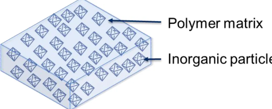
For example, among those studies, Mixed-matrix membranes (MMMs) have been most widely studied to hybridize nanoporous particles and polymer.8 MMMs consist of dispersed inorganic porous solids and polymer matrix to obtain hybrid materials having flexible form factor of polymer and the desired properties of porous solids (Figure 1). This concept has been studied for decades with porous solids such as zeolites, porous carbon especially towards high performance gas separation
membranes.
Figure 1. Concept of Mixed-matrix membranes.
Zeolites are porous minerals consist of metal-oxide bonds, and applied for separations, gas sorption, and catalysis.1, 10 The narrow pore size of zeolites is suitable for separating gas molecules with similar size, such as O2, N2, CO2, CH4 etc.. While, porous carbon such as activated carbon have also shown the excellent size-sieving abilities towards small molecules.11 Because the trade-off between permeability and selectivity is observed in pure-polymer gas separation membranes (known as the
Robeson Upper bound),12, 13 zeolite particles or activated carbon powder have been used as a filler in an attempt to exploit the size-sieving effect of the narrow pore size via creating MMMs to improve the separation performance of pure polymer membranes.10,
14
3
These MMMs are mostly prepared through physically mixing of particles and polymer matrix. Most widely used method to prepare the physically mixed MMMs is simple particle dispersion and casting methods. In the typical approach, the solution including homogeneously dispersed inorganic particles, polymer and organic solvent is casted on the substrate, heated to evaporate the solvent, producing the physically mixed MMMs. This method has been widely used for fabricating MMMs with various porous particles and polymers towards a wide range of applications. As thick MMMs can also be fabricated with this physical mixing method, flexible and easy-handling free-standing MMMs can be readily obtained.
In general, higher particle loading (e.g., over 50 wt %) is desired to make the most of the capability of porous particles in MMMs, and a thinner film is preferable in many applications. For example, in separation membranes, thinner membrane results in greater flux, which is important toward commercialization. The parameter of permeability (P, barrer, defined as a transport flux per unit transmembrane pressure difference per unit membrane thickness) is used to evaluate the separation capability of the membrane material, and the parameter of permeance (Q, GPU, defined as a transport flux per unit transmembrane pressure difference, meaning pressure normalized flux) is used to evaluate the membrane capabilities. There is a correlation that permeance (Q) is in inverse proportion to membrane thickness (l) and in proportion to permeability (P):15
𝑄 =𝑃 𝑙 The unit of permeability (P) is barrer, defined as
1 𝑏𝑎𝑟𝑟𝑒𝑟 = 1 × 10⁻¹⁰ 𝑐𝑚3(𝑆𝑇𝑃) × 𝑐𝑚 𝑐𝑚2 × 𝑠 × 𝑐𝑚𝐻𝑔 The unit of permeance (Q) is GPU, defined as
1 𝐺𝑃𝑈 = 1 × 10⁻⁶ 𝑐𝑚3(𝑆𝑇𝑃) 𝑐𝑚2 × 𝑠 × 𝑐𝑚𝐻𝑔
In the practical applications, permeance (Q) that is the pressure normalized flux is the important parameter because it finally defines the efficiency of the membrane modules.
Based on the correlation above, thinner membranes such as submicron-scale thin
membrane are preferable. Therefore, a thinner film with high particle loading is one of the most desired factors in fabricating MMMs.
Despite the extensive works with MMMs with porous solids towards high particle loading thin MMMs, there are still limitations: suboptimal structures (“sieve- in-a-cage” and “plugged sieves”) and non-uniform morphologies such as aggregations.
4
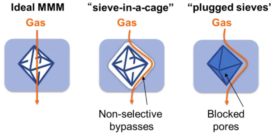
The suboptimal structures including defective interfaces between the particles and polymers (called “sieve-in-a-cage” structure) and blocked pore of porous materials (called “plugged sieves” structure) result in poorer separation performances compared with desired ideal MMMs (Figure 2).8 These undesired suboptimal structures are caused by insufficient control of the interface between inorganic particles and polymer matrix, and the porous particles do not control the separation of gas molecules in these structures.
Figure 2. Ideal and suboptimal structures of MMMs.
The poor particle/polymer compatibility can result in “sieve-in-a-cage”
structures (Figure 3).16, 17 In case of this architecture, the space between particles and polymer matrix is generated, causing nonselective bypass pathways for gas molecules.
As particles are not involved in the separation mechanism in this structure, the desired size-sieving properties of the filler are not obtained, which result in the decreased or maintained selectivity at best. Though permeability would increase due to the bypass pathways, this architecture causes the pinhole defects especially in thin films as thinner films tend to be susceptible to the pinhole formation. The critical pinhole defects defeat the ability of the membranes to separate.18, 19 The pinhole defects cause a non- selective convection transport, resulting in the significant decrease of selectivity.
On the other hand, the pores of the porous solids can be blocked with the small molecules and polymer chains, which results in “plugged sieves” structures.8 In this structure, the gas molecules are not able to pass through the pore of the filler, having to circumvent the blocked particles, passing through longer pathway, resulting in the decrease of gas permeability.
Non-uniform morphologies such as severe aggregation often occur in
physically mixed MMMs with high particle loading (over 50 wt %), even though high particle loading is desired. The particle aggregation generates the macrovoids or
5
pinhole, resulting in a severe decrease of selectivity. These non-uniform structures are caused by the poor particle dispersibility in the polymer matrix and a lack of particle assembly control.
Therefore, towards the high-performance porous solids/polymer hybrid films including MMMs, the precise control of the particle/polymer interface is essential.
Developing the way to control the interfaces between porous solids and polymer would avoid suboptimal and non-uniform structures, generating the new materials including films to overcome current limits of porous solids/polymer hybrid materials towards diverse applications.
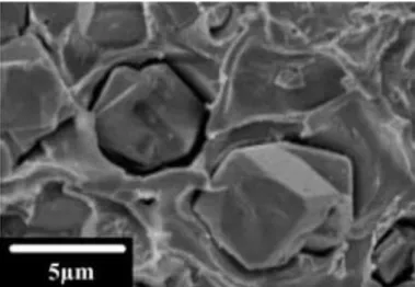
Figure 3. The example of “sieve-in-a-cage” structure: MMMs with Zeolite 4A particles.20
6
Metal-Organic Frameworks (MOFs)
To control the interface between nanoporous materials and polymer, Metal- organic frameworks (MOFs) also known as Porous coordinating polymers (PCP) have been sought after because of their distinctive properties. MOFs are three-dimensional crystalline porous materials with inorganic metal ions and rigid organic linkers, which are connected with coordination bonds (Figure 4).21-23 Therefore, MOFs have both properties of organic and inorganic materials in contrast to other porous solids like zeolites, which is the significant advantage towards the integration of inorganic porous materials and polymer.22 For example, the particle/polymer interfaces in the hybrid materials can be controlled by modifying the organic linker of the inorganic MOF particles with organic reagents, which also enables to tune the diverse chemical functionality of MOFs towards the specific applications. Moreover, due to their unique structure, MOFs demonstrate the extraordinary high surface area with uniform nanopores. As MOFs can be designed with the countless combinations of metal ions and organic linkers, the extensive structural variety and the tunable porosity can be achieved. In addition, MOFs can be synthesized with simpler and more processable conditions compared to conventional porous inorganic materials like zeolites, which enables MOF materials to access to the commercial applications.24 By taking
advantage of these unique properties, MOFs have demonstrated exceptional separation, storage, and catalysis capacities, pushing the limits of the nanoporous inorganic
materials toward a wide range of applications over the last two decades.2-5, 25 Therefore, MOFs have a particularly high potential towards MOF-polymer hybrid materials due to the organic/inorganic functionality for the control of particle/polymer interfaces, the diverse chemical tunability, the high surface area with uniform
nanopores, structural varieties, and simple synthesis conditions.
7 Figure 4. Metal-organic frameworks (MOFs)
8
MOFs for Film Application
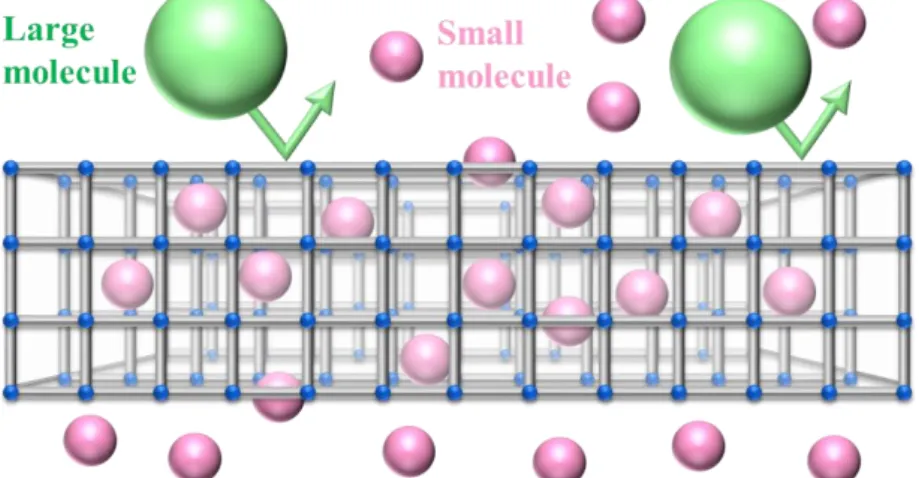
To date, pure-MOFs films have shown the potential to the practical application such as separation membranes, adsorptive films, battery separators, and sensors and so on.9, 26 For example, pure-MOF membranes have shown the excellent features in gas separation in terms of selectivity and permeability. Because the uniform MOF pores are an ideal structure for the size-sieving and the high porosity of MOFs allows more gas molecules to pass through the membranes, the high selectivity and permeability have been achieved (Figure 5). For example, separation membranes with ZIF-8 (ZIF:
Zeolitic Imidazolate Framework), a class of zinc-based MOFs, have shown the excellent separation performances. ZIF-8 membrane shows the great propylene permeability and propylene/propane selectivity beyond Robson upper bound which is the trade-off limit of polymer membranes.27
Towards practical applications, though the pure-MOF films are brittle and have a poor processability due to their crystalline nature as well as other inorganic materials like zeolites, MOFs have a great potential to achieve the high performance porous solids-polymer hybrid films by taking advantage of the unique MOF properties such as the controllable particle/polymer interfaces.
Figure 5. Size-sieving property of MOF-based separation membrane.
9
MOF-Polymer Hybrid Materials
Therefore, hybridizing MOFs having a high performance towards practical application and flexible polymer would generate the novel flexible and processable nanoporous materials. A number of efforts towards combining the properties of MOFs and the flexible nature of polymer have been performed, showing the advance of the utility of MOFs. Recently, various approaches to create MOF-polymer hybrid materials have been studied, which includes MMMs,28 polymers grafted from MOF particles,29 polymerization in MOFs, polymers templating MOF growth, MOFs composed of polymer ligands (PolyMOFs).30-34 (Figure 6). These approaches are classified into two strategies; top-down and bottom-up approaches. Top-down approach is the way where MOF particles are initially synthesized and subsequently hybridized with polymer (e.g., MMMs).28 While bottom-up approach is the way where MOF-polymer hybrid materials are synthesized when MOF formation is
proceeding (e.g., PolyMOFs). Some of these approaches about MOF-polymer hybrid materials would create a platform to utilize these materials toward practical
applications. Among these strategies, top-down approaches including MOF-based MMMs have been most widely studied towards MOF-polymer hybrid fims.28
Figure 6. Overview of MOF-Polymer hybrid materials.35
10
MOF-Polymer Hybrid Films
By taking advantage of the unique properties of MOFs, where MOF has both properties of organic and inorganic materials, a numbers of efforts to control the MOF/polymer interface have been performed in the top-down approach of MOF-based MMMs.22 Various approaches have been studied to obtain improved MMMs
especially for the gas separation application for a decade.7, 35 Since some MOFs demonstrate higher flux and selectivity than polymer-only membranes, the
incorporation of MOF particles in polymer matrix have been sought after towards high performance gas separation membranes.
In MOF-based MMMs, there are two main approaches to control the MOF/polymer interfaces. First approach is MMMs fabricated through the
conventional simple physical mixing with unmodified MOF particles and polymer in order to generate noncovalent bonding such as - stacking or hydrogen bonding between MOF particles and polymer matrix. The second approach involves the chemical modification of the organic ligands of MOF particles in order to improve the surface properties of the particles.
The second approach of MMMs with modified MOF particles have attracted the enormous attention recently because most MMMs in first approach are focusing on relatively low MOF loadings (less than 40 wt %). Especially, the modification MOF particles with polymer offers a variety of approaches to tailor MOF surface properties towards desired MMMs. For example, by attaching polymers to the MOF linker with covalent bonds, it is possible to introduce the strong interactions at the particle/polymer interface, which shows the potential to achieve the complete integration of MOF and polymer components towards the desired MOF/polymer hybrid films.
11
MOF Modification Methods
Compared to other porous solids like zeolites, one of the great advantages of MOF materials is the unique ability for the modification. In order to control
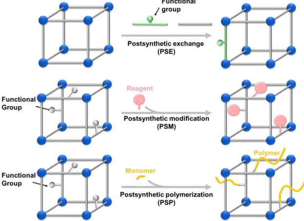
MOF/polymer interface in MMMs, it is a strong tool to modify presynthesized MOF particles through postsynthetic manners such as postsynthetic exchange (PSE), postsynthetic modification (PSM), postsynthetic polymerization (PSP) (Figure 7).36 These unique methods make it possible to generate functional MOFs that are not
accessible from direct synthesis, and to functionalize the surface of the MOF particles.
Through PSE reaction, linkers in MOF particles are readily replaced with other linkers without loss of MOF crystallinity or porosity.37 In the case that the newly introduced linker is bigger than the pore size of MOF particles, PSE reaction tend to proceed only on the particle surface leaving the inside pore intact, which result in the surface modification of the MOF particles.
PSM is a process involving the reaction with reagents and MOF particles.36 The reagents react with the functional groups of organic linkers or metal nodes, which results in the functionalization of MOF particles. When the reagents react with the functional groups of the organic linkers and form covalent bonds, the strong connection between MOFs and the newly introduced components can be achieved. If reagents are balky, the modification can occur only on the particle surface.
In PSP reaction, a polymer chain grows from the functional groups of linkers as a “grafting-from” method.38, 39 The covalent surface modification of MOF particles with polymer can be achieved through the PSP reaction. By attaching the
polymerization initiator to the MOF linker, a living radical polymerization can be used for the PSP reaction, resulting in the precise control of the polymerization.
Through these postsynthetic methods or combination of these, the modification of the surface properties of MOFs without loss of original MOF properties can be achieved, enabling the precise control of MOF-polymer interface towards MOF- polymer hybrid materials.
12
Figure 7. Schemes of Postsynthetic methods: postsynthetic exchange, postsynthetic modification, postsynthetic polymerization.
13
Core-Shell MOFs Approach
One of the interesting approaches to modify MOF particles is to utilize core- shell MOFs with polymer shell. Polymer shells provide unique properties: a strong adhesion of covalent bonds between inorganic MOF particles and organic polymer shell; a good dispersibility in organic solvent or polymer matrix; further reactions form the functional groups in the polymer shell; protection of MOF pores from pore-
blocking; adhesions of each particles via physical interactions of the flexible polymer shell and so on.
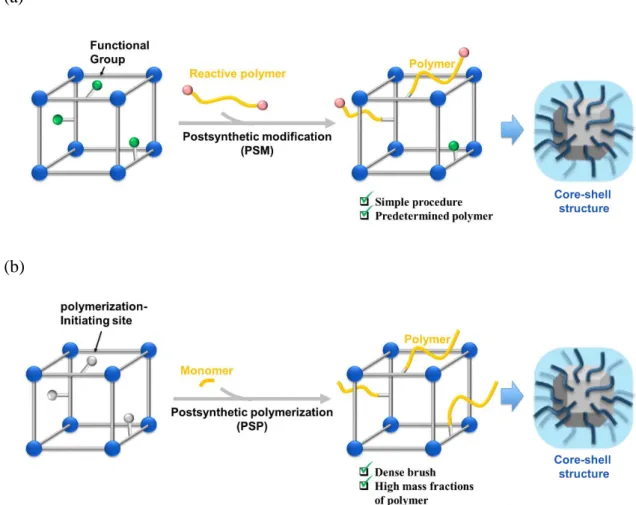
There are two common methods to synthesize core-shell MOF particles;
“grafting-to” and “grafting-from” method.35, 40-43 A “grafting-to” method is achieved through PSM reactions with presynthesized polymers with reactive groups and MOF particles with functional groups. As the polymer can be prepared with precise control of the molecular weight and dispersity prior to PSM reaction, the shell size of core-shell MOFs is controlled facilely with a simple procedure. It is a significant advantage to characterize the properties of the polymer before the “grafting-to” reaction. However, the grafting density tend to be poor through the “grafting-to” method, which limits the amount of polymer on the MOF particles.
In contrast, “grafting-from” method is performed through PSP reaction with MOF particles modified with polymerization-initiating sites.44 The polymers are grown from the initiating sites through PSP reaction. This method generates highly dense polymer brushes and results in large amount of polymer on the MOF particles.
In this method, a living radical polymerization such as Atom transfer radical
polymerization (ATRP) can be applied and the dense polymer shell can be achieved.
Though several studies about these approaches towards MMMs with good MOF/polymer compatibility have been reported,38, 45-51 it is still challenging to achieve high MOF-loaded MOF-polymer hybrid films, especially in the case of thin films.
14 (a)
(b)
Figure 8. Schemes of grafting routes: (a) “Grafting-to” method. (b) “Grafting-from”
method
15
Purpose of This Research
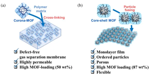
In this study, in order to control the MOF-polymer interfaces and to achieve MOF-polymer hybrid materials towards high MOF-loaded thin films, we synthesized core-shell structured MOFs with the polymer shell (termed “corona-MOF” in Chapter 1, termed “core-shell MOF” in Chapter 2) (Figure 9). The polymer chain of the shell is covalently integrated to the surface of the MOF particles using postsynthetic methods such as PSM, PSE, and PSP in order to obtain core-shell structured MOF particles. By using core-shell structured MOFs, the flexible MOF-polymer hybrid films with high MOF loading were achieved. Additionally, to demonstrate the potential of the core- shell strategy, we also synthesized thin MMMs with high MOF loading and the high MOF loading monolayer with ordered particles.
In Chapter 1, we synthesized a PDMS-decorated MOF (termed here “corona- MOF”) by covalently grafting allyl-functionalized UiO-66 (UiO-66-Allyl) (UiO:
University of Oslo) with hydride-terminated poly(dimethylsiloxane) (PDMS) as a
“grafting-to” method. The corona-MOFs and PDMS polymer matrix were used to fabricate defect-free MMMs for gas separation membranes. The hydrophobic corona generates the excellent particle dispersibility in the PDMS polymer matrix, and the cross-linking of the corona and PDMS polymer matrix with covalent linkages gives strong MOF/polymer adhesion. These factors allowed for fabrication of the defect- free MMMs with 50 wt % MOF loading. The single gas separation tests demonstrated the improved separation performance of corona-MOF MMMs, showing the significant advantage of corona-MOFs strategy. This strategy is also able to be used for the fabrication of free-standing flexible thin films (<1 μm thickness) without any apparent macrovoids, which demonstrates the applicability of this concept towards practical applications.
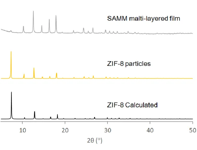
In Chapter 2, we synthesized porous monolayers and free-standing multilayer films via self-assembly. Despite a lot of efforts towards fabricating monolayers with nanoparticles for various applications, densely ordered porous thin monolayers have not been reported. The self-assembled MOF monolayers (termed here “SAMMs”) were achieved with core-shell MOF particles via a liquid-air interface method, resulting in an extremely thin MOF/polymer hybrid film with the controlled particle assembly. Core- shell MOFs were obtained by synthesizing the layer of poly(methyl methacrylate) (PMMA) on ZIF-8 particles using a histamine anchor via ATRP reaction (“grafting- from” method). SAMMs were obtained as thin films with 87 wt % (89 vol %) MOF loading and the intact porosity. Additionally, MOF multilayers such as alternating
16
MOF/polymer heterostructures were synthesized by stacking SAMMs. SAMMs were also able to be covered on the three-dimensional object such as silicon microparticles, and free-standing self-assembled films with five-particle thickness showing opalescence were also fabricated. This achievement of MOF-polymer monolayer is a significant advancement for creating a platform towards various applications such as porous membranes and coatings. To the best of our knowledge, this study is the first report about self-assembled porous monolayer and free-standing self-assembled multilayer films composed of MOF nanoparticles.
(a)
(b)
Figure 9. Purpose of this research: (a) Defect-free MOF-based MMMs obtained by corona cross-linking for gas separation. (b) Self-assembly of MOF nanoparticle monolayers.
17
References
1. Rangnekar, N.; Mittal, N.; Elyassi, B.; Caro, J.; Tsapatsis, M., Zeolite membranes – a review and comparison with MOFs. Chemical Society Reviews 2015, 44 (20), 7128-7154.
2. Kirchon, A.; Feng, L.; Drake, H. F.; Joseph, E. A.; Zhou, H. C., From fundamentals to applications: a toolbox for robust and multifunctional MOF materials.
Chem Soc Rev 2018, 47 (23), 8611-8638.
3. Li, J. R.; Sculley, J.; Zhou, H. C., Metal-organic frameworks for separations.
Chem Rev 2012, 112 (2), 869-932.
4. Suh, M. P.; Park, H. J.; Prasad, T. K.; Lim, D. W., Hydrogen storage in metal-organic frameworks. Chem Rev 2012, 112 (2), 782-835.
5. Khan, N. A.; Hasan, Z.; Jhung, S. H., Adsorptive removal of hazardous materials using metal-organic frameworks (MOFs): a review. J Hazard Mater 2013, 244-245, 444-56.
6. Li, Y.; Li, L.; Yu, J., Applications of Zeolites in Sustainable Chemistry.
Chem 2017, 3 (6), 928-949.
7. Dechnik, J.; Gascon, J.; Doonan, C. J.; Janiak, C.; Sumby, C. J., Mixed- Matrix Membranes. Angew. Chem. Int. Ed. 2017, 56, 9292-9310.
8. Rezakazemi, M.; Ebadi Amooghin, A.; Montazer-Rahmati, M. M.;
Ismail, A. F.; Matsuura, T., State-of-the-Art Membrane Based CO2 Separation Using Mixed Matrix Membranes (MMMs): An Overview on Current Status and Future Directions. Prog. Polym. Sci. 2014, 39, 817-861.
9. Li, W., Metal–organic framework membranes: Production, modification, and applications. Progress in Materials Science: Vol. 100, pp 21-63.
10. Bastani, D.; Esmaeili, N.; Asadollahi, M., Polymeric mixed matrix
membranes containing zeolites as a filler for gas separation applications: A review. J.
Ind. Eng. Chem. 2013, 19, 375-393.
11. Saufi, S. M.; Ismail, A. F., Fabrication of carbon membranes for gas separation––a review. Carbon 2004, 42 (2), 241-259.
12. Robeson, L. M., The Upper Bound Revisited. J. Membr. Sci. 2008, 320, 390- 400.
13. Robeson, L. M.; Liu, Q.; Freeman, B. D.; Paul, D. R., Comparison of transport properties of rubbery and glassy polymers and the relevance to the upper bound relationship. Journal of Membrane Science 2015, 476, 421-431.
14. García, M. G.; Marchese, J.; Ochoa, N. A., High activated carbon loading
18
mixed matrix membranes for gas separations. Journal of Materials Science 2012, 47 (7), 3064-3075.
15. Freeman, B. D., Yampolskii, Y., Pinnau, I, Materials Science of Membranes for Gas and Vapor Separation. John Wiley & Sons: 2006.
16. Lin, R.; Villacorta Hernandez, B.; Ge, L.; Zhu, Z., Metal Organic Framework Based Mixed Matrix Membranes: An Overview on Filler/Polymer Interfaces. J. Mater. Chem. A 2018, 6, 293-312.
17. Anjum, M. W.; Vermoortele, F.; Khan, A. L.; Bueken, B.; De Vos, D.
E.; Vankelecom, I. F. J., Modulated UiO-66-Based Mixed-Matrix Membranes for CO2 Separation. ACS Appl. Mater. Interfaces 2015, 7, 25193-25201.
18. Gao, X.; Zhang, J.; Huang, K., ROMP for Metal–Organic Frameworks: An Efficient Technique toward Robust and High-Separation Performance Membranes. ACS Appl. Mater. Interfaces 2018, 10, 34640-34645.
19. Park, H. B.; Kamcev, J.; Robeson, L. M.; Elimelech, M.; Freeman, B. D., Maximizing the Right Stuff: The Trade-Off Between Membrane Permeability and Selectivity. Science 2017, 356, eaab0530.
20. Moore, T. T.; Koros, W. J., Non-ideal effects in organic–inorganic materials for gas separation membranes. Journal of Molecular Structure 2005, 739 (1), 87-98.
21. Meek, S. T.; Greathouse, J. A.; Allendorf, M. D., Metal-Organic
Frameworks: A Rapidly Growing Class of Versatile Nanoporous Materials. Adv. Mater.
2011, 23, 249-267.
22. Yaghi, O. M.; O'Keeffe, M.; Ockwig, N. W.; Chae, H. K.; Eddaoudi, M.; Kim, J., Reticular Synthesis and the Design of New Materials. Nature 2003, 423, 705-714.
23. Eddaoudi, M.; Kim, J.; Rosi, N.; Vodak, D.; Wachter, J.; O'Keeffe, M.; Yaghi, O. M., Systematic design of pore size and functionality in isoreticular MOFs and their application in methane storage. Science 2002, 295 (5554), 469-72.
24. Stock, N.; Biswas, S., Synthesis of metal-organic frameworks (MOFs): routes to various MOF topologies, morphologies, and composites. Chem Rev 2012, 112 (2), 933-69.
25. Yuan, S.; Feng, L.; Wang, K.; Pang, J.; Bosch, M.; Lollar, C.; Sun, Y.; Qin, J.; Yang, X.; Zhang, P.; Wang, Q.; Zou, L.; Zhang, Y.; Zhang, L.;
Fang, Y.; Li, J.; Zhou, H. C., Stable Metal-Organic Frameworks: Design, Synthesis, and Applications. Adv Mater 2018, 30 (37), e1704303.
26. Shekhah, O.; Chernikova, V.; Belmabkhout, Y.; Eddaoudi, M., Metal–
Organic Framework Membranes: From Fabrication to Gas Separation. Crystals: 2018;
19 Vol. 8, p 412.
27. Kwon, H. T.; Jeong, H.-K., In Situ Synthesis of Thin Zeolitic–Imidazolate Framework ZIF-8 Membranes Exhibiting Exceptionally High Propylene/Propane Separation. J. Am. Chem. Soc. 2013, 135, 10763-10768.
28. Denny Jr, M. S.; Moreton, J. C.; Benz, L.; Cohen, S. M., Metal–organic frameworks for membrane-based separations. Nat. Rev. Mater. 2016, 1, 16078.
29. Wang, H.; He, S.; Qin, X.; Li, C.; Li, T., Interfacial Engineering in Metal–Organic Framework-Based Mixed Matrix Membranes Using Covalently Grafted Polyimide Brushes. J. Am. Chem. Soc. 2018, 140, 17203-17210.
30. Ayala, S.; Bentz, K. C.; Cohen, S. M., Block co-polyMOFs: morphology control of polymer-MOF hybrid materials. Chem Sci 2019, 10 (6), 1746-1753.
31. Ayala, S.; Zhang, Z.; Cohen, S. M., Hierarchical structure and porosity in UiO-66 polyMOFs. Chem Commun (Camb) 2017, 53 (21), 3058-3061.
32. Schukraft, G. E. M.; Ayala, S.; Dick, B. L.; Cohen, S. M., Isoreticular expansion of polyMOFs achieves high surface area materials. Chem Commun (Camb) 2017, 53 (77), 10684-10687.
33. Zhang, Z.; Nguyen, H. T.; Miller, S. A.; Ploskonka, A. M.; DeCoste, J.
B.; Cohen, S. M., Polymer-Metal-Organic Frameworks (polyMOFs) as Water Tolerant Materials for Selective Carbon Dioxide Separations. J Am Chem Soc 2016, 138 (3), 920-5.
34. Zhang, Z.; Nguyen, H. T.; Miller, S. A.; Cohen, S. M., polyMOFs: A Class of Interconvertible Polymer-Metal-Organic-Framework Hybrid Materials. Angew Chem Int Ed Engl 2015, 54 (21), 6152-7.
35. Kalaj, M.; Bentz, K. C.; Ayala, S.; Palomba, J. M.; Barcus, K. S.;
Katayama, Y.; Cohen, S. M., MOF-Polymer Hybrid Materials: From Simple Composites to Tailored Architectures. Chem Rev 2020.
36. Cohen, S. M., Postsynthetic Methods for the Functionalization of Metal–
Organic Frameworks. Chem. Rev. 2012, 112, 970-1000.
37. Kim, M.; Cahill, J. F.; Su, Y.; Prather, K. A.; Cohen, S. M., Postsynthetic ligand exchange as a route to functionalization of ‘inert’ metal–organic frameworks.
Chemical Science 2012, 3 (1), 126-130.
38. Yao, B.-J.; Jiang, W.-L.; Dong, Y.; Liu, Z.-X.; Dong, Y.-B., Post- Synthetic Polymerization of UiO-66-NH2 Nanoparticles and Polyurethane Oligomer toward Stand-Alone Membranes for Dye Removal and Separation. Chem. Eur. J. 2016, 22, 10565-10571.
39. Kalaj, M.; Denny Jr., M. S.; Bentz, K. C.; Palomba, J. M.; Cohen, S. M.,
20
Nylon–MOF Composites through Postsynthetic Polymerization. Angewandte Chemie International Edition 2019, 58 (8), 2336-2340.
40. Dukes, D.; Li, Y.; Lewis, S.; Benicewicz, B.; Schadler, L.; Kumar, S.
K., Conformational Transitions of Spherical Polymer Brushes: Synthesis, Characterization, and Theory. Macromolecules 2010, 43, 1564-1570.
41. Hansson, S.; Trouillet, V.; Tischer, T.; Goldmann, A. S.; Carlmark, A.;
Barner-Kowollik, C.; Malmstrom, E., Grafting Efficiency of Synthetic Polymers onto Biomaterials: A Comparative Study of Grafting-from versus Grafting-To.
Biomacromolecules 2013, 14, 64-74.
42. Radhakrishnan, B.; Ranjan, R.; Brittain, W. J., Surface Initiated Polymerizations from Silica Nanoparticles. Soft Matter 2006, 2, 386-396.
43. Bentz, K. C.; Savin, D. A., Chain Dispersity Effects on Brush Properties of Surface-Grafted Polycaprolactone-Modified Silica Nanoparticles: Unique Scaling Behavior in the Concentrated Polymer Brush Regime. Macromolecules 2017, 50, 5565- 5573.
44. Xie, K.; Fu, Q.; Kim, J.; Lu, H.; He, Y.; Zhao, Q.; Scofield, J.;
Webley, P. A.; Qiao, G. G., Increasing Both Selectivity and Permeability of Mixed- Matrix Membranes: Sealing the External Surface of Porous MOF Nanoparticles. J.
Membr. Sci. 2017, 535, 350-356.
45. Gao, X.; Zhang, J.; Huang, K.; Zhang, J., ROMP for Metal–Organic Frameworks: An Efficient Technique toward Robust and High-Separation Performance Membranes. ACS Appl. Mater. Interfaces 2018, 10, 34640-34645.
46. Molavi, H.; Shojaei, A.; Mousavi, S. A., Improving Mixed-Matrix Membrane Performance via PMMA Grafting from Functionalized NH2–UiO-66. J. Mater. Chem.
A 2018, 6, 2775-2791.
47. Tien-Binh, N.; Rodrigue, D.; Kaliaguine, S., In-Situ Cross Interface Linking of PIM-1 Polymer and UiO-66-NH2 for Outstanding Gas Separation and Physical Aging Control. J. Membrane Sci. 2018, 548, 429-438.
48. Yao, B.-J.; Ding, L.-G.; Li, F.; Li, J.-T.; Fu, Q.-J.; Ban, Y.; Guo, A.;
Dong, Y.-B., Chemically Cross-Linked MOF Membrane Generated from Imidazolium- Based Ionic Liquid-Decorated UiO-66 Type NMOF and Its Application toward CO2 Separation and Conversion. ACS Appl. Mater. Interfaces 2017, 9, 38919-38930.
49. Zhang, Y.; Feng, X.; Li, H.; Chen, Y.; Zhao, J.; Wang, S.; Wang, L.; Wang, B., Photoinduced Postsynthetic Polymerization of a Metal-Organic
Framework toward a Flexible Stand-Alone Membrane. Angew. Chem., Int. Ed. 2015, 54, 4259-4263.
21
50. Jiang, W.-L.; Ding, L.-G.; Yao, B.-J.; Wang, J.-C.; Chen, G.-J.; Li, Y.-A.; Ma, J.-P.; Ji, J.; Dong, Y.; Dong, Y.-B., A MOF-Membrane Based on the Covalent Bonding Driven Assembly of a NMOF with an Organic Oligomer and its Application in Membrane Reactors. Chem. Commun. 2016, 52, 13564-13567.
51. Satheeshkumar, C.; Yu, H. J.; Park, H.; Kim, M.; Lee, J. S.; Seo, M., Thiol–Ene Photopolymerization of Vinyl-Functionalized Metal–Organic Frameworks Towards Mixed-Matrix Membranes. J. Mater. Chem. A 2018, 6, 21961-21968.
22
Chapter 1
Defect-Free MOF-Based Mixed-Matrix Membranes Obtained by Corona Cross-
Linking for Gas Separation
Abstract
Allyl-functionalized UiO-66 (UiO: University of Oslo) type Metal-organic framework (MOF) particles were grafted with hydride-terminated
poly(dimethylsiloxane) (PDMS) with covalent bonds via “graft-to method” as
postsynthetic modification (PSM). The PDMS-grafted particles (termed here “corona- MOFs”) were utilized to fabricate high MOF loaded Mixed-matrix membranes
(MMMs) with PDMS polymer matrix. Because the PDMS corona possesses unreacted terminal hydride group, it can be further reacted with PDMS polymer matrix.
Therefore, the corona is bound to both the particles and the polymer matrix, acting as a bridge, creating a strong MOF/polymer matrix adhesion. Attributed to the improved MOF/polymer matrix adhesion with covalent linkages and the dispersibility of the particles in the polymer matrix, 50 wt % defect-free MOF-loaded MMMs were achieved.
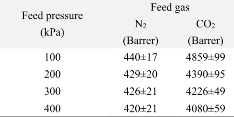
In single gas permeation tests, the corona-MOF MMMs demonstrated the higher CO2 gas permeability than PDMS-only membrane without loss of the selectivity, which shows distinct property of corona-MOF MMMs. On the other hand, MMMs with undecorated MOF particles showed the decreased selectivity, indicating the presence of pinholes. To identify the separation mechanism of corona-MOF MMMs, the permeability of various sized gases such as CO2, N2, and propane were measured with single gas separation tests. The results show that the corona-MOF MMMs demonstrate the size-sieving ability, which supports the fact that the separation mechanism of corona-MOF MMMs is an “ideal MMMs” scenario which avoids sub- optimal “sieve-in-a-cage” and “plugged sieves” structures.
In addition, by taking advantage of the strong MOF/polymer adhesion and the
23
excellent dispersibility of the particles in the polymer matrix, the self-standing thin MMMs (<1 μm in thickness) with good flexibility were achieved. The covalently attached corona of low quantities of polymer (<5 wt %) acts an important role in fabricating the defect-free, high MOF-loaded thin MMMs.
24
Introduction
One of the most attractive applications of Metal-organic frameworks (MOFs) is MOF-based separation membrane.1-3 Since separation membranes can separate
without phase change and heat, membrane separations can drastically reduce the energy consumption compared to the conventional distillation, which is the most common separation method now in various purification processes. For example, Sholl et al.
reported that the chemical separations such as hydrocarbon separation, separation of alkenes from alkanes and separation of benzene derivatives from each other, account for half of the US industrial energy consumption and 10-15 % of the world’s energy use, suggesting one potential way to reduce the huge energy use is to apply separation membranes. As separation membranes require 90% less energy than distillation (Figure 1−1), developing high performance separation membranes would generate a huge impact on industrial processes.4 One attractive strategy is to develop MOF-based membranes. Because their uniform and tunable nanopores can be suitably applied to the size-sieving separations, separation membranes with MOFs have a huge potential for the future separation processes.
Figure 1−1. Total US energy consumption and the potential of membrane separation for energy reduction. 4
25
As discussed in general introduction, several efforts have performed to prepare pure-MOF membranes, where the thin MOF active layer is synthesized on the porous substrate such as ceramic supports through secondary growth, seeded growth or direct growth methods.1, 2, 5-7 As an uniform pore size and versatile functionalities of MOFs are suitable for separating molecules, pure-MOF membranes show excellent separation performances such as permeability and selectivity. However, due to their crystalline nature, the brittleness and poor processability limit the industrial applications. In addition, expensive rigid porous ceramic substrates are widely used to support the brittle MOF active layer, which also hampers pure-MOF membranes from the
commercialization. Though there are some efforts to use organic polymer substrates instead of inorganic substrates,8-11 the complicated processes to deposit MOF active layer on the polymer substrate and the careful handling of fragile MOF active layer still limit the application of the membrane in the industry.
One of the alternative route toward fabricating MOF membranes is Mixed- matrix membranes (MMMs) (Figure 1, see General introduction).12-14 MMMs consist of dispersed inorganic porous solids and polymer matrix to make hybrid materials having flexible form factor of polymer and the desired properties of porous solids.
MMMs have shown a potential to obtain an outstanding separation performance derived from size-sieving effects of porous solids with a good processability and flexibility.
Additionally, fabricating free-standing MMMs or MMMs on flexible polymer substrates can avoid the use of expensive inorganic substrates, which is a significant advantage towards commercial applications. To surpass the upper bound that is the trade-off relationship of the permeability and the selectivity in conventional polymeric membranes, selecting the suitable combinations of porous solids and polymers for separating molecules is required, which have been studied for decades.15
For maximizing the potential of MOF-based MMMs, it is essential to synthesize “ideal” MMMs, and avoid suboptimal structures and non-uniform morphologies (vide supra). In ideal MMMs, gas molecules permeate through the MOF pore and are separated with MOF properties such as size-sieving effects.16-18 However, suboptimal structures such as “sieve-in-a-cage” or “plugged sieves” and non- uniform morphologies such as particle aggregations often hamper the ideal structure, as discussed in general introduction (Figure 2).17 In these undesired structures, MOF particles cannot control the gas permeation in the membrane. The “sieve-in-cage”
scenario and non-uniform morphologies such as particle aggregations often cause critical pinhole defects with a non-selective convection transport, resulting in the significant decrease of the selectivity especially in MMMs at high MOF loadings with
26
submicron-scale thickness. On the other hand, in “plugged sieves” structures, the gas molecules cannot enter the pore of the filler, having to circumvent the blocked particles, passing through longer pathway, resulting in the decrease of gas permeability without increasing selectivity.
Therefore, the control of MOF/polymer interface is crucial to achieve defect- free high-MOF loaded MMMs.16, 19 By taking advantage of the MOF modification methods discussed in General introduction, the surface functionalization of MOF particles can be readily achieved, which differs from the conventional inorganic particles such as zeolites (Figure 7). Therefore, MOFs are attractive materials to control MOF/polymer interfaces and create the ideal MMMs with high-MOF loading.
Recently, MOF-based MMMs with improved particle dispersibility and the MOF/polymer interface have been reported. The improvement of MOF/polymer interaction has been achieved with π-π stacking, van der Waals forces, hydrogen bonding and so on. For example, preparing polymers with hydroxyl groups has reported to introduce hydrogen bonding between MOF/polymer interface. Another example shows the positive effect of π-π stacking between MOF particles and polymer matrix via introducing the aromatic substituents on the MOF particles.20-23
Some efforts have demonstrated improved MOF/polymer interaction via polymer grafting on the surface of MOF particles. The grated polymer can physically interact with polymer matrix, resulting in the improved interaction between MOF and polymer matrix. For example, MMMs with polymer-grafted UiO-66 (UiO: University of Oslo) type MOFs have been reported; poly(ethylene glycol methacrylate) (PEGMA) was grafted on the initiator-functionalized UiO-66 through controlled radical
polymerization (Figure 1−2a), poly(methyl methacrylate) (PMMA) was also grafted through glycidyl methacrylate functionalized UiO-66-NH2, and polyimides (PI) brushes was introduced on the surface of UiO-66-NH2 via step growth polymerization (Figure 1−2b). 24-26 In the latter example, the covalently grafting of PI brushes produced the core-shell MOF, showing the PI brush amount was 12 wt % of the MOF particles (Figure 1−2b).26 As the selected PI polymer matrix for MMMs was compositionally identical to PI brushes, PI-grafted UiO-66-NH2 showed excellent dispersibility in the PI polymer matrix. As PI brushes are not covalently crosslinking with polymer matrix, the interaction between PI brushes and polymer matrix is van der Waals force. The obtained MMMs demonstrated an improved plasticization resistance under CO2 high pressure condition, ductility and an improved gas separation performance for CO2/N2
and CO2/CH4. However, though this strategy produced MMMs with 43 wt % MOF loadings, clear macrovoids are observed in scanning electron microscopy (SEM)
27
images, indicating the complete MOF/polymer integration was not achieved. And the ability to form thin films using this material was not reported.
(a)
(b)
Figure 1−2. Example of MOF-based MMMs with controlled surface properties of MOF particles: (a) MMMs using MOFs grafted with PEGMA thorough surface-initiated atom transfer radical polymerization (ATRP).24 (b) UiO-66-NH2 grafted with polyimide, which is used for fabricating MMMs.27
28
To obtain the improved MOF/polymer interaction, several reports have
introduced covalent bonds between them using methods such as cross-linking with heat treatment,28 condensation reactions,27, 29 photopolymerization,30-32 in situ cross-linking during polymer synthesis,25, 33 or ring-opening metathesis polymerization (ROMP).34
For example, Gao et al. introduced covalent bonds between MOF and polymer matrix with ROMP as a postsynthetic polymerization (PSP), producing 50wt% MOF loaded MMMs. The MMMs demonstrated improved gas separation performance for H2/CO2 and H2/N2 (Figure 1−3).34 However, SEM images of MMMs show
macroscopic voids between the MOF particles, demonstrating the poor dispersibility and the aggregation of MOF particles, which indicates a suboptimal “sieve-in-a cage”
morphology. The 20 wt% MOF-loaded thin MMMs with 5 μm thickness were also fabricated on porous supports, however, high MOF-loaded thin MMMs such as 50 wt % MOF-loaded thin MMMs were not reported.
Yao et al. also reported MMMs with UiO-66 functionalized with imidazolium- based ionic liquids. (Figure 1−4).27 The covalent linkage was introduced by cross- linking of hydroxy groups of the functional MOF particles and isocyanate groups in polymer matrix of polyurethane oligomers, and the resulting MMMs with 50 wt% MOF loading demonstrated improved selectivity and permeability compared to the polymer- only membranes. However, the poor permeability of polyurethane polymer matrix caused low permeability of MMMs.
29
Figure 1−3. (a) MOF-based MMMs synthesized through ring-opening metathesis polymerization (ROMP). (b) Fabrication of MMMs via ROMP. (c) Optical images of MMMs.34
Figure 1−4. Fabrication of covalently cross-linked MMMs with the polyurethane oligomer.27
30
The careful selection of polymer matrix is essential to design high-MOF loaded MMMs for gas separation, because the polymer matrix should have both capabilities of gas separation performance and processability including flexibility. Among a bunch of polymers, poly(dimethylsiloxane) (PDMS) is one of the attractive membrane materials, as this rubbery polymer readily forms flexible thin films with high gas permeability.
PDMS is one of silicone polymers having excellent flexibility and the most widely used silicone polymer in practical applications. Therefore, a variety of functional silicones are commercially available, such as PDMS functionalized with acrylate, vinyl, alcohol, hydride, vinyl groups, and branched PDMS and so on, allowing for the diverse ways for the modification (Figure 1−5). In rubbery materials including PDMS, condensable gases such as CO2 can permeate faster than poorly condensable gases such as N2, resulting in solubility selectivity.35, 36 Since silicone membranes have already been commercialized for several applications such as organic solvent nanofiltration and gas separation, MMMs with PDMS potentially have an ability to scale. 37, 38
a)
b) c)
d)
Figure. 1−5 Chemical structure of various PDMSs; (a) trimethylsiloxy terminated PDMS, (b) hydride terminated PDMS, (c) vinyl terminated PDMS, (d) silanol terminated PDMS.
Though there are a number of studies on PDMS MMMs, few studies about MMMs with MOF particles and PDMS have been reported. MOF-PDMS MMMs also suffer from the suboptimal structures like “sieve-in-a-cage” or “plugged sieves”
structures and the particle aggregation as with the example of MMMs with other inorganic particles such as zeolites. One of the challenges of MOF-PDMS MMMs is the integration of relatively hydrophilic MOF particles and hydrophobic PDMS polymer matrix. To date, MOF-PDMS MMMs with 40 wt % MOF loading have been achieved using physical mixing method.39 However, these MMMs demonstrated a decreased selectivity due to the macrovoids derived from the insufficient MOF/polymer
interaction. Bae et al. reported MOF-PDMS MMMs with Mg2(dobdc) (MOF-
74(Mg)), fabricating MMMs with 20 wt % MOF loading via physical mixing method.40 However the MMM demonstrated decreased permeability, indicating the “plugged sieves” suboptimal structure. Therefore, in order to avoid theses undesired structures,
31
the precise control of the MOF/polymer interface in MOF-PDMS MMMs is required.
In this study, in order to improve MOF/polymer interaction and particle dispersibility and to avoid suboptimal structures and non-uniform morphologies,
hydride-terminated PDMS was grafted to the surface of MOF particles, generating core- shell structured MOFs (termed here “corona-MOF”); and the corona-MOF was used to fabricate PDMS MMMs with 50 wt % MOF-loading (Figure 1−6). In corona-MOF MMMs, the corona is connected to both MOF particles and PDMS polymer matrix with covalent bonds, acting as a bridge between the MOF particles and polymer matrix, resulting in the strong MOF/polymer matrix connection. Additionally, the PDMS corona is compositionally identical to PDMS polymer matrix, which eliminates any boundary between the corona and the polymer matrix, resulting in an excellent particle dispersion in the polymer matrix. These benefits of corona strategy can generate defect-free high MOF-loaded MMMs. In addition, this corona-MOF MMM avoids
“plugged sieves” suboptimal structure due to the steric buffer of the corona, resulting in the improved gas permeability. Although some studies about PDMS-grafted MOF particles have been reported,41-46 this is the first study that achieved the covalent integration of MOF particles and PDMS polymer matrix, and also the first report about defect-free MOF-PDMS MMMs with 50 wt% MOF loading without any suboptimal structures. Moreover, due to the excellent MOF/polymer interactions and strong MOF/polymer linkage with covalent bonds, flexible MMMs with the thickness of <1 μm was fabricated without macrovoids, which demonstrates the potential of this corona- MOF approach towards thin MMMs for practical applications.
Figure 1−6. Corona-MOF MMMs with PDMS polymer matrix.
32
Experimental Section
Ligand Synthesis
Starting materials were purchased and used from commercially available suppliers (Sigma-Aldrich, Matrix Scientific, Acros Organics, and others) and used without further purification.
Dimethyl 2-bromoterephthalate (1). Compound 1 was synthesized according to literature procedures (Inorganic Chemistry 2011, 50, 729-731). Yield: 90 %. 1H NMR (400 MHz, CDCl3): δ 8.31 (d, J = 1.5 Hz, 1H), 8.00 (dd, J = 8.1, 1.4 Hz, 1H), 7.81 (d, J = 8.1 Hz, 1H), 3.95 (d, J = 4.4 Hz, 6H).
2-Allylterephthalic acid (3). To a 250 mL round bottom flask was added compound 1 (7.00 g, 25.6 mmol), tetrakis(triphenylphosphine) palladium (0) (0.59 g, 0.51 mmol, 0.02 eq), and allyltributylstannane (8.74 mL) in 120 mL of toluene. The solution was heated to reflux under N2 for 5 days. After cooling, the reaction solution was
quenched using 30 mL of a 4% CsF solution and the obtained precipitate was removed by filtration. The filtrate was extracted with ethyl acetate and dried with magnesium sulfate. The crude product was purified using flash chromatography with silica gel to give the desired product dimethyl 2-allylterephthalate (2), which was used for the next reaction without further purification.
To a 500 mL of round bottom flask was added compound 2 in 100 mL of THF and 100 mL of 4% KOH solution. The solution was stirred at room temperature for 24 h. 100 mL of water was added and THF was removed by evaporation, and the aqueous solution was washed twice with hexane. The aqueous layer was acidified to pH ~1 with conc. HCl to precipitate a white solid that was collected by filtration and dried under vacuum to give the desired product (compound 3). Yield: 81 % (over two steps from 1). 1H NMR (400 MHz, d6-DMSO): δ 7.97 – 7.83 (m, 3H), 6.18 – 5.81 (m, 1H), 5.16 – 4.98 (m, 2H), 3.78 (d, J = 6.5 Hz, 2H). ESI-MS Experimental: 205.06.
Calculated for [C12H15O5]-: 205.06.
33
Model reaction for Postsynthetic modification (PSM) (4). To a 3.7 mL vial were added compound 2 (10 mg, 0.043 mmol), hydride terminated polydimethylsiloxane (average Mn ~580, Sigma-Aldrich) (50 mg, 0.085 mmol) and platinum(0)-1,3-divinyl- 1,1,3,3-tetramethyldisiloxane complex solution (in xylene, Pt ~2%, 5 μL, Karstedt’s Catalyst), in 2 mL of toluene. The capped vial was heated to 100 °C for 30 min in an oven. After cooling to room temperature, toluene was removed by evaporation to give a crude compound 4. Conversion of the allyl group of dimethyl-2-allylterephthalate was calculated by measuring a crude compound 4 with 1H NMR (400 MHz, CDCl3).
The allyl group of crude compound 4 disappeared after the reaction (Figure 1-9).
MOF Syntheses
UiO-66-Allyl. 3 (43 mg, 0.21 mmol) and Zirconium(IV) chloride (48 mg, 0.21 mmol) were dissolved in the mixture of 12 mL DMF, 3.6 mL glacial acetic acid and 7.5 μL water in a 20 mL vial. The capped vial was heated to 120 °C for 24 h in an oven.
After cooling to room temperature, the particles were collected with centrifugation (fixed-angle rotor, 6500 rpm, 15 min). The particles were washed with 3×10 mL portions of MeOH, and dried under vacuum at room temperature. Yield: 83%. The crystallinity was confirmed by PXRD to be UiO-66 (Figure 1−9), and the particle shapes were confirmed by SEM to be octahedral ~300 nm particles (Figure 1−10).
BET surface area (m2/g) was measured to be 783 m2/g. The pore size distribution was measured with N2 at 77 K on a Micromeritics ASAP 2020 (Figure 1−28).
UiO-66-Allyl-C. UiO-66-Allyl (200 mg) was dispersed in 20 mL toluene using sonication in an ultrasonic bath for 30 min. Hydride terminated polydimethylsiloxane (average Mn ~580, Sigma-Aldrich, 40 mg) was added to the MOF suspension. The combined suspension was sonicated for 30 min. Platinum(0)-1,3-divinyl-1,1,3,3- tetramethyldisiloxane complex solution (Karstedt’s Catalyst, in xylene, Pt ~2%, 40 μL) was then added to the suspension. The suspension was sonicated for 30 min with an ultrasonic bath, and then the suspension was stirred and the capped vial was heated to 100 °C for 24 h. After cooling to room temperature, the particles were collected with centrifugation (fixed-angle rotor, 6500 rpm, 15 min). The collected particles were washed with 3×40 mL portions of THF, soaked with THF for 24h, and dried under vacuum at room temperature. Yield: 91% based on the UiO-66-Allyl quantity (PDMS quantity was subtracted using the digestion results (Table 1−1)). The crystallinity was confirmed by PXRD to be UiO-66 (Figure 1−9), and the particle shapes were confirmed by SEM to be octahedral ~300 nm particles (Figure 1−10).
34
BET surface area (m2/g) was measured to be 734 m2/g. The pore size distribution was measured with a Micromeritics ASAP 2020 (Figure 1−28).
UiO-66-Allyl+PDMS. UiO-66-Allyl (200 mg) was dispersed in 20 mL toluene using sonication for 30 min. Hydride terminated polydimethylsiloxane (40 mg, average Mn
~580, Sigma-Aldrich) was then added to the MOF suspension. The combined suspension was sonicated for 30 min in an ultrasonic bath. Then the suspension was stirred, and the capped vial was heated to 100 °C for 24 h in an oven. After cooling to room temperature, the particles were collected by centrifugation (fixed-angle rotor, 6500 rpm, 15 min). The collected particles were washed with 3×40 mL portions of THF, soaked with THF for 24 h, and dried under vacuum at room temperature. Yield:
99% based on the UiO-66-Allyl quantity (PDMS quantity was subtracted using the digestion results (Table 1−1)). The crystallinity was confirmed by PXRD to be UiO- 66 (Figure 1−9), and the particle shapes were confirmed by SEM to be octahedral ~300 nm particles (Figure 1−10). BET surface area (m2/g) was measured to be 767 m2/g.
UiO-66. Terephthalic acid (35 mg, 0.21 mmol) and zirconium (IV) chloride (48 mg, 0.21 mmol) were dissolved in the mixture of 12 mL DMF and 3.6 mL glacial acetic acid. The capped vial was heated to 120 °C for 24 h in an oven. After cooling to room temperature, the particles were collected by centrifugation (fixed-angle rotor, 6500 rpm, 15 min). The collected particles were washed with 3×10 mL portions of MeOH, and dried under vacuum at room temperature. Yield: 83 %. The pore size distribution was measured using a Micromeritics ASAP 2020 (Figure 1−28).
Digestion of MOF particles. 10.0 mg of dry MOF particles were immersed in mixture of 350 μL NaOD solution (40 wt % in D2O) with bath sonication for at least 3 h. Next, 350μL of D2O was added, the residue was removed by centrifugation (fixed- angle rotor, 10000 rpm, 5 min), and collected supernatant was used as the solution for NMR analysis (Figure 1−11).
35 Membrane Fabrication
Mixed matrix membranes (MMMs). In a 20 ml vial, 200 mg of dry MOF powder was dispersed in 5.0 mL of acetone using sonication for 30 min. A mixture of 182 mg of RTV615A and 18 mg of RTV615B in 0.87 mL of toluene was added to the MOF suspension such that the final MOF:PDMS ratio was 1:1 w/w. The combined
MOF/PDMS suspension was sonicated for 1 h in an ultrasonic bath. Then acetone was removed by evaporation until the total solution weight was ~1 g, resulting in a MOF
‘ink’ which consists of MOF, PDMS and toluene. Coatings were prepared on BYTAC substrates (Teflon Resin Surface Protectors, Aluminum Backing, purchased from Saint Gobain Performance Plastics) and a glass plate. The Teflon surface of BYTAC was effective to prevent MMM films from sticking to the substrate. The ink was cast onto BYTAC which was put on the glass plate. Films were formed by bar coating with spacer thickness of 200 µm. The coated films were then heated in an isothermal oven to crosslink the polymer and remove the solvent (at 100 °C for 24h. The thickness of the MMMs prepared this way were ~20-60 μm determined with Mitutoyo Digital Micrometer (0.001 mm resolution, 0-25 mm range, IP 54 standard) and also checked via cross section SEM image. PXRD patterns of these MMMs are shown in Figure 1−19 and SEM images are shown in Figure 1−20 − 1−22.
PDMS membranes for gas separation tests. The mixture of 500 mg of RTV615A, 50 mg of RTV615B, and 250 mg of toluene was cast onto BYTAC substrates. Films were formed by bar coating with 300 µm thickness. Then the coated films were heated to crosslink and remove solvent in an isothermal oven at 100 °C for 24 h. The
thickness of the freestanding membrane was ~100 μm. Since thin PDMS membranes are difficult to handle, PDMS membranes were prepared to be thicker than MMMs.
PDMS membrane for DMA. A mixture of 2.13 g of RTV615A, 213 mg of
RTV615B, and 4.26 g of toluene was cast into a PTFE evaporating dish purchased from VWR International. The casted solution was then heated and dried to crosslink and remove solvent (60 °C, 24h) using a hotplate, then heated to 100 °C, 24h in an isothermal oven. The thickness of PDMS membranes was 620 μm.
Thin MMMs. 45 mg of dry MOF powder was dispersed in 1 mL acetone using sonication in a 20 ml vial for 30 min. A mixture of 41 mg of RTV615A, 4.1 mg of RTV615B, and 340 mg of toluene was added to the MOF suspension such that the final MOF:PDMS matrix ratio was 1:1 w/w. The combined MOF/PDMS suspension was
36
sonicated with an ultrasonic bath for 1 h, then the acetone was removed by evaporation until total solution mass was 300 mg, resulting in a MOF ‘ink’ which consist of MOF, PDMS and toluene. The ink was cast onto BYTAC to prevent MMM films from sticking to the substrate (Figure 1−32). Films were formed by bar coating with wet film applicator rods No. 4 (AP-JR-04 purchased from Gardco, wet film thickness is 10 μm). The coated films were then heated to crosslink and remove solvent at 100 °C for 24 h in an isothermal oven. The obtained thin MMMs were peeled off from the coating substrate with masking tape which reinforced the edge of the thin film for easy handling. SEM images of thin MMMs are shown in Figures 1−34 − 1−36.
Characterization
Nuclear magnetic resonance (NMR). 400 MHz Varian FT-NMR spectrometer was used to record proton nuclear magnetic resonance spectra (1H NMR). Chemical shifts are measured in parts per million (ppm) with a reference of the appropriate solvent peak.
Powder X-ray diffraction (PXRD). For the analysis with PXRD, ~50 mg of dry MOF powder or 0.5 cm2 of MMM was put on silicon sample holder. A Bruker D8 Advance diffractometer was used and PXRD data was collected at room temperature, at 40 kV, 40 mA for Cu Ka (l = 1.5418 Å), with a scan speed of 2 sec/step, a step size of 0.05° in 2θ, and a 2θ range of 2-50°.
Brunauer-Emmett-Teller (BET) surface area analysis and pore size distribution measurement. Prior to analysis, samples were evacuated on a vacuum line at room temperature overnight. Then, ~50 mg samples were put to pre-weighed sample tubes and degassed at 105 °C until the outgas rate was less than 5 mmHg on a Micromeritics ASAP 2020 Adsorption Analyzer. After degassing, the sample tubes were re-weighed to get a mass for the samples. BET surface area (m2/g) were measured with N2 at 77 K with a Micromeritics ASAP 2020 Adsorption Analyzer using volumetric techniques.
Pore size distribution data were calculated from the N2 sorption isotherms at 77K based on N2-DFT model (density functional theory model, slit pore geometry,
regularization=0.001) in the MicroActive software provided from Micromeritics.
37
Scanning electron microscopy (SEM). MOF particles or MMM films (~3 mm2) were put on conductive carbon tape attached to a SEM sample holder disk and coated using an Iridium-sputter coating for 8 s. A FEI Quanta 250 SEM instrument was used to measure images with an energy source of 5 kV at a working distance at 10 mm under vacuum.
Dispersibility test of MOF particles. ~7 mg MOF particles were dispersed in 7 mL of toluene. After 30 min sonication, the solutions were allowed to settle and
dispersibility was visually confirmed at every various times (Figure 1−12).
Contact angle measurements. Contact angle were measured with a CAM Micro (Tantec). The MOF powder (approximately 5-10 mg) was pressed onto a glass plate with another glass plate. A drop of water was slowly dropped on the pressed sample with a microsyringe and then the contact angle was measured (Figure 1−12).
Dynamic light scattering (DLS). 10 mg/mL solutions of UiO-66-Allyl, UiO-66- Allyl+PDMS, and UiO-66-Allyl-C in toluene were prepared and hydrodynamic
diameters were measured to determine the degree of dispersibility of the particles. The MOF solution of 10 mg/mL MOF particles in toluene was sonicated for 30 min to disperse MOF particles, in pre-cleaned quartz cuvettes prior to analysis. DLS was performed on a Malvern Zetasizer ZS90 (Malvern, UK) at 90° (Figures 1−13 − 1−15), and hydrodynamic diameters were obtained from number-averaged weighted
calculations from fitting the autocorrelation functions to distribution fits.
Scanning electron microscopy - Energy dispersive X-ray spectroscopy (SEM- EDX). MMMs were adhered to a SEM sample holder disk with conductive carbon tape to measure cross sectional views. To obtain images , an FEI Quanta FEG 250 ESEM instrument was used under vacuum with a 10 kV energy source at a working distance at 10 mm for SEM. Energy dispersive X-ray spectroscopy (EDX) spectra were measured with a 10 kV energy source via the attached Thermo Scientific Pathfinder EDX system (Figure 1−17, Table 1−2).
38
Dynamic mechanical analysis. Storage moduli data were acquired using Perkin Elmer Dynamic Mechanical Analyzer 8000 (Waltham, MA). Sample thickness was measured using a Mitutoyo Digital Micrometer (0-25 mm range, 0.001 mm resolution, IP 54 standard). Measurement areas were approximately 5mm width and 5mm length.
Frequency sweeps at 0.1Hz to 35 Hz with strains of 0.05 mm were used. All samples were run in triplicate and the average of all measurements was shown with error bars calculated as a standard deviation(Figure 1−23). The dynamic elastic modulus, also known as storage modulus, E’, is a quantity that describes the resistance of a material to elastic deformation, or more generally is related to the stiffness of a material.
Application of a sinusoidal stress, σ, to a material results in a sinusoidal strain response, ε, shifted by a quantity δ, known as the phase angle. The ratio of the applied stress to strain response gives the complex modulus, E*. Finally, the storage modulus at any particular frequency, ω, is given by:
𝐸′(𝜔) = |𝐸∗| ∙ cos 𝛿
where cos δ represents the real, in-phase, component of the strain response.