マイクロチャネル内二相流に対する有限要素解析
Finite element analysis for two phase flow in micro channels
○正 倉橋 貴彦(長岡技科大) 曵地 玲香(長岡技科大院) 正 古口 日出男(長岡技科大)
Takahiko Kurahashi, Nagaoka University of Technology, 1603-1 Kamitomioka, Nagaoka, Niigata,
Reika Hikichi, Graduate School of Nagaoka University of Technology, 1603-1, Kamitomioka-cho, Nagaoka-shi, Niigata Hideo Koguchi, Nagaoka University of Technology, 1603-1, Kamitomioka-cho, Nagaoka-shi, Niigata Key Words: Finite element method, Stabilized bubble function element, Two phase flow, Micro channel
1. は じ め に
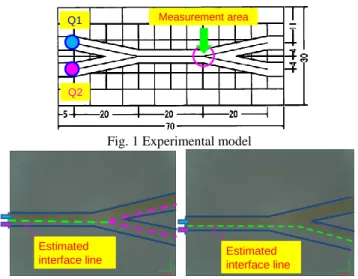
小スペースにおける短時間の反応や,マイクロスケールの 粒子を対象とする液体に混入させる等の目的で,図 1 に示す マイクロ化学チップが近年着目されている.現在マイクロ化 学チップは,研究段階にあり,様々な利用法について模索さ れているが,①ダイオキシンをはじめとする環境分析に対す る利用,②アレルギーなどの医用分析、抗ガン剤の製造など 薬品合成等の医療分野に対する適用,③エネルギーの分野で は「小型の燃料電池(携帯電話のバッテリー等)」の作成,
④化粧品の分野ではエマルジョン化粧品の作成,⑤文具の分 野ではエマルジョンインクの作成等,幅広い分野における利 用が期待される.
マイクロ化学チップの利用の際の問題点の一つとして,マ イクロ流路における多層流の形成が困難であることが挙げ られる[1].実際に図1に示すチップを用いてデジタルマイク ロスコープ(倍率540倍)により界面観察を行った結果を図 2に示す.図1におけるQ1(染色液(23℃:純水+サンセッ トイエロー))およびQ2(アセトン(23℃))を同流量とし,5 μl/min,50μl/minと設定したところ,50μl/minでは,染色 液がアセトン側に入り込む結果となったことに対し,5μl/mi においては界面位置がおおむね流路中心線上で安定する結 果を得た.5μl/minを下回る流量設定にした実験では,両種 の液体が混合する結果となり,界面安定における流量設定の 上下限界の幅が狭いことが想定される.そこで,本検討では,
マイクロ流路内の界面安定性に関する検討に先立ち,マイク ロ流路内における二層流に対する有限要素解析を行う.本検 討では,安定化気泡関数有限要素法を適用する.
Measurement area Q1
Q2
Fig. 1 Experimental model
Estimated
interface line Estimated
interface line Case 1 Case2
Fig. 2 Pictures by digital microscope (Magnification:×540) Case 1: Q1 = 5μl/min Q2 = 5μl/min,
Case 2: Q2 = 50μl/min Q2 = 50μl/min
2. 基礎方程式
本検討では,流れ場を表現するために,式(1)に示す運動 方程式と式(2)に示す連続式,また,界面位置を表す輸送方 程式を用いる.
ij ji
j iV ij i j
i VV P V V f
V , 1 , , , ,
………(1)
,i 0
Vi ………(2)
, 0
Vii
………(3) ここに,Viは流速,Pは圧力である.また,νは動粘性係数,
ρは密度,fiVは外力(チップを水平に置いているため,重 力項は無視し,本検討では体積力のみを外力として考慮す る.),φは界面形状を表す指標関数(以後,指標関数)を示 す.また表面(界面)張力を表す CSF モデル[2]では,体積力 fiVは式(4)の様に表される.式(4)における
x は表面(界面)曲率を表しており,式(5)により与えられる.
x x x x
fiV i
] [
, ………(4)
ii
i
i n
x
1
n , ,n n
n ………(5) ここに,は表面(界面)張力係数であり, ,
および界面上における法線ベクトルniは,
1 2
2
1
,
21(12),ni,iと与えられる.3. 基礎方程式の離散化
式(1)に対してオイラー法による時間方向の離散化を行い,
得られた式の発散を取り,式(2)を陰的に表現した式を代入 することにより,式(6)に示す圧力ポアソン方程式が得られ る.
i n
j i n j n
i n i
ii V V
t P V
, . 1 ,
, ………(6) 式(6)を解くことで圧力場が得られ,得られた圧力分布を式 (7)に示す運動方程式(式(1)に対してオイラー法を適用する ことで得られる式)に代入することで,流れ場を求めること ができる.
n
j i n
i j n
j i n i n
j i n j n i n
i V t V V P V V f
V 1 , 1 , 1 , , ,
……(7)
式(7)により得られた流れ場を式(8) (式(3)に対してθ法を適 用することで得られる式)に代入することで,界面の位置の 判別を行うことができる.
nin i n n i n i
n1 t1 V 1, 1 tV ,
……(8)
ここにθは0≦θ≦1で設定される値であり,指標関数φの 値が,0.5≦φあるいはφ<0.5 により流体の種別を分けるこ とができる.
式(6)~(8)を有限要素法により離散化するため,流速に対 しては気泡関数要素,圧力に対しては三角形一次要素,指標 関数に対しては気泡関数要素を適用する(図 3).また,式
(7),(8)については,SUPG 法と等価となる数値粘性を要素重
心点のみに付与する安定化パラメータを導入する[3].
Velocity Pressure
4
~ Vi 3
Vi
1
Vi Vi2 P1 P2
P3
4
~
1 2
3
Index function
Fig. 3 Element type
4. 数値解析例 4.1 キャビティ流れに対する検証例題
流れ解析結果の精度を確認するため,図4に示すキャビテ ィ流れの問題に対して検証を行う.Ghiaらの解析結果[4]は精 度が高く比較に良く用いられる.レイノルズ数を100とし,
上面における流速値(境界条件の値)により正規化した
x=0.5mm, y=0.5mm上における流速分布(実線)とGhiaらの
結果(十字点)の比較を図5に示す.両者とも良い一致を示 しており,高精度に計算を行えていることを確認できる.
Total number of nodes : 2,061 Total number of elements : 5,000 Δt : 10-5sec
Convergence criterion,
6 1
ˆ 10
x n n
V U U
U Vx2Vy2
Kinematic eddy viscosity ν: 0.893, mm2/s Density ρ: 10×10-6,kg/mm3
: 89.3,mm/sec, Reynolds number: Re=100 Vˆx
Wall : Vx0, Vy0 on 2
0 1
ˆ,
V V on
Vx x y
Top surface :
0 Corner : P
Fig. 4 Cavity model and computational conditions
A A’
B B’
Fig. 5 Distribution of each velocity component on x = 0.5mm(left) and y=0.5mm(right) (Computational velocity is normalized by
velocity on top surface. )
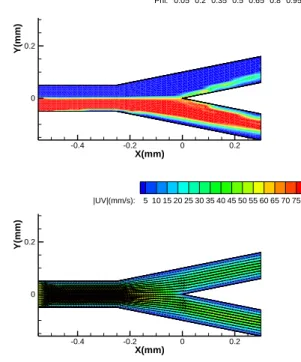
4.2 CSFモデルを用いたマイクロ流路内の2層流流れ解析 次に表面(界面)張力効果を考慮したマイクロ流路内の 2 層流れの結果を示す.解析モデルおよび境界条件を図 6 に示 す.図 2 の観察結果に基づき,水とアセトンの流入量を 5μ l/min(水側:Re=2.7×10-3,アセトン側:Re=5.7×10-3)と 設定し,解析を行った.指標関数値と流速分布を図 7 に示す.
分岐部において,指標関数値が上部と下部に対して完全に分 離した結果とはなっていないが,適切な流れ場の基,界面の 移動過程を良好に表せているものと考えられる.
Q2(Acetone) 5μl/min Vx2= 50.30mm/s Vy2=0.0mm/s, φ1=1 Q1(Water) 5μl/min Vx1=50.30mm/s Vy1=0.0mm/s, φ1=0
Q1(Water) ν: 0.938, mm2/s ρ: 9.979×10⁻⁶,kg/mm3
Q2(Acetone) ν: 0.444, mm2/s ρ: 7.770×10⁻⁶,kg/mm3 50μm
50μm Vx1,Vx2=0.0mm/s
Vx1,Vx2=0.0mm/s
Vx1,Vx2=0.0mm/s P=0MPa
P=0MPa 100μm
100μm Total number of nodes : 1,836
Total number of elements : 3,400 Δt: 10-6sec
Parameter θin θ method : 0.5
Surface tension (Asetone 20℃) σ1: 23.3×10⁻⁶N/mm, (Water 20℃) σ2: 72.75×10⁻⁶N/mm Interface tension : σ12 ≒σ1+ σ2– 2 (σ1σ2)1/2 = 13.71×10⁻⁶N/mm
Fig. 6 Computational model and boundary definition
X(mm)
Y(mm)
-0.4 -0.2 0 0.2
0 0.2 0.4 0.6
Phi: 0.05 0.2 0.35 0.5 0.65 0.8 0.95
X(mm)
Y(mm)
-0.4 -0.2 0 0.2
0 0.2 0.4 0.6
Phi: 0.05 0.2 0.35 0.5 0.65 0.8 0.95
X(mm)
Y(mm)
-0.4 -0.2 0 0.2
0 0.2 0.4 0.6
|UV|(mm/s): 5 10 15 20 25 30 35 40 45 50 55 60 65 70 75
X(mm)
Y(mm)
-0.4 -0.2 0 0.2
0 0.2 0.4 0.6
|UV|(mm/s): 5 10 15 20 25 30 35 40 45 50 55 60 65 70 75
Fig. 7 Computational results at T=0.025sec.
(Upper: Index function, Lower: Velocity distribution)
5. おわりに
本稿では,安定化気泡関数有限要素法に基づくマイクロス ケール流路内における流れ解析結果を示した.今後は,実験 による観察結果との比較より現象の再現性について更なる 検討を行う予定である.
謝辞
本研究を行うにあたり科学研究費補助金(若手(B))23760149 の援助を受けた.ここに謝意を表す.
参考文献
[1] Arata Aota, Akihide Hibara, and Takehiko Kitamori, Pressure Balance at the Liquid-Liquid Interface of Micro Countercurrent Flows in Microchips, Anal. Chem., 79, pp.3919-3924, 2007.
[2] J.U. Brackbill, D.B.Kothe and C.Zemach, Continuum method for modeling surface tension, Journal of computational physics.
100, pp.335-354, 1992.
[3] J.Matsumoto, A.A.Khan, S.S.Y.Wang and M.Kawahara, Shallow Water Flow Analysis with Moving Boundary Technique Using Least-squares Bubble Function, International Journal of Computational Fluid Dynamics, 16, (2), pp.129-134, 2002.
[4] U.Ghia,K.N.Ghia and C.T.Shin, High-Re Solutions for Incompressible Flow Using the Navier-Stokes Equations and a Multigrid Method, J. Compt. Phy., 48, 387-411, 1982.