Evaluation of Friction Durability of Extremely Thin Diamond-Like Carbon Films by Statistical Cluster and Regression Analyses of Friction Coefficient
12
0
0
全文
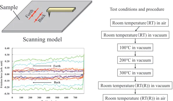
(2) Shojiro Miyake and Masatoshi Miyake magnetic disks, softer substrate materials, such as NiP, are used. Therefore, there is a need to study the tribology properties for different substrate materials. In the present study, to clarify the durability properties for actual application, we used statistical cluster analysis to study the effect of the substrate (NiP or Si) on the tribological properties (such as friction coefficient and durability) for extremely thin DLC films at high temperature. The films were deposited using FCVA and P-CVD. The nanotribology and durability properties were evaluated using AFM and a friction tester, respectively. The friction durability of the films was evaluated using statistical cluster and regression analyses.. 2 Experimental methods 2.1 Specimens Approximately-2-nm-thick DLC films on NiP and Si substrates were used as specimens. These films were deposited using FCVA and P-CVD [9]. The thicknesses were evaluated using transmission electron microscopy (TEM). The surface profile change (roughness (Ra)) of the thin films was evaluated using AFM with a carbon-nanotube tip. There was only a small difference in the surface roughness between films prepared with FCVA and P-CVD. The roughness values of the films on NiP and Si were approximately 0.32 and 0.15 nm, respectively, which were similar to those of the substrates themselves [9, 14]. 2.2 Evaluations of nanomechanical properties 2.2.1 Nanoindentation test The nanoindentation properties of the films were investigated using AFM (Digital Instruments Nanoscope III) with a nanoindentation measurement system (Hysitron Inc.) [25]. The loading time was 20 s and the maximum load was 600 μN. The elastic and plastic deformation properties of the films were evaluated from the load dependence of the nanoindentation depth curves.. 2.2.2 Nanofriction test The dependence of the nanotribology properties on the surface temperature of films was evaluated using environmentally-controlled AFM (SII 38000) [9]. The testing method is shown in Fig. 1. The relative friction force is defined as half of the difference between the “back” and “forth” directions of the friction curves. A cantilever with a ~150-nm-radius diamond tip was used. To avoid damage to the electrical parts of the AFM, nanofriction tests at high temperatures were performed in vacuum. Samples were placed in the vacuum chamber and the nanofriction test was first performed at room temperature (~20°C) in air. Then, the chamber was evacuated to achieve a vacuum of 6 × 10⁻⁵ Pa using rotary and turbo-molecular pumps. The nanofriction test was then conducted at room temperature in vacuum, after which the specimen temperature was changed from room temperature to 100, 200, and 300°C with tests carried out at each temperature using a different testing position on the sample each time. The temperature was then returned to room temperature and the test was repeated in vacuum and in air. Tests were performed by sliding the tip under loads from 500 to 4500 nN and scanning over an 800-nm length. After the sliding test, the surface profiles were observed using the same tip, and the wear profiles were evaluated. The wear depth was evaluated from the topographic change of the area subjected to sliding friction by measurement using AFM [8, 14, 17, 23, 26, 27]. Each nanofriction test was performed more than three times, and the average value was reported. 2.3 Evaluation of the friction and durability 2.3.1 Friction To evaluate how the friction properties of the film depend on load, the friction coefficient was measured using a load increase-and-decrease type friction tester [9], a schematic view of which is shown in Fig. 2. A 2-mm-diameter Al2O3-TiC ball was used as the opposing surface. The sliding width was 10 mm, and the speed was 5 mm/s. The applied load was changed from 0.05 to 0.5 N. The total number of reciprocating cycles was 100. The specimen surfaces were heated by infrared light, and. Sample. Test conditions and procedure Room temperature(RT) in air Room temperature(RT) in vacuum. Scanning model. 100℃ in vacuum. 0.40. Friction force [arb. unit]. 0.30. 200℃ in vacuum. 0.20. Forth. 0.10. 300℃ in vacuum. 0.00 -0.10. Back. Room temperature(RT(R)) in vacuum. -0.20 -0.30 0. 100. 200. 300. 400 500 Position [nm]. 600. 700. Fig. 1. Japanese Society of Tribologists (http://www.tribology.jp/). Room temperature (RT(R)) in air Nanofriction test. Tribology Online, Vol. 16, No. 2 (2021) /114.
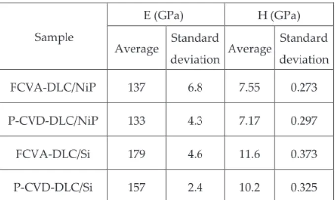
(3) Evaluation of Friction Durability of Extremely Thin Diamond-Like Carbon Films by Statistical Cluster and Regression Analyses of Friction Coefficient. Reciprocating Load. Ball. Specimen Load weight. Undulation sensor Specimen. Spirit level. Friction sensor Heater. Counter weight. Reciprocation. Table Cooling device. Ball Fig. 2. Load increase and decrease reciprocating friction test. the surface temperatures were measured using a thermocouple fixed on the specimen surface. The surface temperature was controlled to ±3°C during the friction test.. 700. 2.3.2 Durability Cluster analysis of the dependence of the friction coefficient on load and number of reciprocating cycles was performed on the data from the friction test using the statistical analysis software R [28]. A hierarchical clustering technique, the k-means method, was used to evaluate the durability of the films. The dependence of the friction coefficient on the load and number of reciprocating cycles was classified into two clusters: a lowfriction region, in which the film was effective (cluster-I), and a high-friction region where the lubricating effect of the film was lost (cluster-II) [9]. There was a certain boundary value of the friction coefficient at which the effectiveness of the DLC film was lost. When the friction coefficient exceeded that value, the region changed from cluster-I, to cluster-II. Thus, the friction durability cycle and critical load could be evaluated from the boundary conditions of these clusters. The durability of the films was evaluated from the number of reciprocating cycles at a certain load endured by the cluster analysis. To clarify the durability mechanism, regression analysis of the friction coefficient dependence on load and reciprocating cycle number of cluster-I was performed [17].. 500. 3 Results and discussion 3.1 Nanomechanical properties 3.1.1 Nanoindentation properties The densities of the FCVA-DLC and P-CVD-DLC films were 3.3 and 1.9 g/cm3, respectively, as evaluated by Rutherford backscattering. The nanoindentation hardness values of these two films at a 40-mN load were 57 and 25 GPa, respectively [8]. The nanoindentation curves of the films on both substrates are shown in Fig. 3. Tests were performed six times, and their average and standard deviation are shown in Table 1. To clarify the dependence of the deformation depth on the substrate material, the maximum load was set at 600 nN. For both. Japanese Society of Tribologists (http://www.tribology.jp/). FCVA-DLC/NiP P-CVD-DLC/Si. Load (nN). 600. Si(100) FCVA-DLC/Si. 400 300 200. P-CVD-DLC/NiP. 100 0. 0. 10. Fig. 3. 20 30 Indentation depth (nm). 40. 50. 60. Nanoindentation properties of DLC films. Table 1. Elastic modulus E and Hardness H. E (GPa) . H (GPa) . Sample . Average . FCVA‐DLC/NiP . 137 . 6.8 . 7.55 . 0.273 . P‐CVD‐DLC/NiP . 133 . 4.3 . 7.17 . 0.297 . FCVA‐DLC/Si . 179 . 4.6 . 11.6 . 0.373 . P‐CVD‐DLC/Si . 157 . 2.4 . 10.2 . 0.325 . Standard deviation . Average . Standard deviation . substrates, the hardness and elastic modulus of the FCVA-DLC film are higher than those of the P-CVD-DLC film. Moreover, on NiP, the indentation depth of the FCVA-DLC film is smaller than that of the P-CVD-DLC film. Films on NiP have lower hardness and elastic modulus than what is found for those on Si, as shown in Fig. 3 and Table 1.. Tribology Online, Vol. 16, No. 2 (2021) /115.
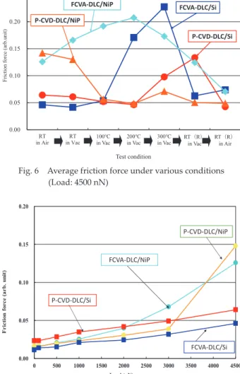
(4) Shojiro Miyake and Masatoshi Miyake. 0.30. 100℃ In Vac. 200℃ In Vac. 300℃ In VAc. RT In Vac. RT In Air. RT(R) In Vac. temperature in air and under vacuum; however, it decreased at higher temperature in vacuum. The FCVA-DLC film had a higher force than the P-CVD-DLC film at 100, 200, and 300°C in vacuum on both substrates. The reason that the friction force is lower on Si than NiP is because of the lower elastic modulus and hardness of NiP. Upon substrate deformation of NiP, the friction of the film increased. The dependence of the friction force on the load at room temperature and at 200°C is shown in Figs. 7 and 8. At room. 0.25. FCVA‐DLC/NiP. P‐CVD‐DLC/Si 0.15. 0.10. 0.05. 0.00. RT in Air. RT in Vac. 100℃ in Vac. 200℃ in Vac. 300℃ in Vac. RT(R) in Vac. RT(R) in Air. Test condition. Fig. 6. RT(R) In Air. Average friction force under various conditions (Load: 4500 nN). 6. 0.20. 0.20 0.10. P‐CVD‐DLC/NiP 0.15. Forth. 0.00. FCVA‐DLC/NiP. Back -0.10 -0.20 -0.30. 0. Fig. 4. 100. 200. 300. 400 500 Position (nm). 600. 700. Friction force (arb. unit). Friction force (arb.unit). FCVA‐DLC/Si . P‐CVD‐DLC/NiP. 0.20 Friction force (arb.unit). 3.1.2 Nanofriction properties The friction curves of the films on NiP at a load of 4500 nN are shown in Figs. 4 and 5. The friction force of the FCVADLC film on NiP (Fig. 4) is high at all temperatures in vacuum. However, it decreased for RT(R) (i.e. the return set of roomtemperature measurements, after the high-temperature testing) in air. By contrast, the friction force of the P-CVD-DLC film on NiP (Fig. 5) is high at room temperature in air and vacuum but is low at higher temperature in vacuum. The friction force is lower for RT(R) in both vacuum and in air, which we attribute to the formation of tribochemical products on the diamond tip during the previous sliding tests. After previous sliding friction tests, the P-CVD-DLC film had formed a lubricating transfer layer on the diamond tip under high temperature in vacuum [29-31], which meant that the friction force for the P-CVD-DLC film in the subsequent RT(R) tests was low. In this case, the transfer layer formed on the diamond tip can reduce the friction force. The dependence of the friction force on the test conditions for the films on both substrates at a load of 4500 nN is shown in Fig. 6. The friction force of the FCVA-DLC film on NiP is higher at high temperature. On both substrates at high temperature, the friction force is higher for the FCVA-DLC film than for the P-CVD-DLC film. On Si, the force for the FCVA-DLC film increased rapidly from 200°C and reached a maximum value at 300°C. The force decreased at RT(R) in vacuum. In contrast, the friction force for the P-CVD-DLC film on NiP was high at room. 0.10. P‐CVD‐DLC/Si 0.05. FCVA‐DLC/Si 0.00. Nanofriction curves of FCVA-DLC/NiP under various conditions (Load: 4500N). RT In Air. 0.20. RT In Vac. 300℃ In Vac. 100℃ In Vac. RT(R) In Vac. RT(R) In Air. 500. 1000. 1500. 2000. 2500. 3000. 3500. 4000. 4500. Load (nN). Fig. 7 0.25. 0. 200℃ In Vac. Nanofriction dependence on load at room temperature. 0.25. 0.10 0.05. Forth. 0.00. -0.10 -0.15 -0.20. Fig. 5. 0. 100. 200. 300 400 Position (nm). FCVA‐DLC/Si. 0.15. Back. -0.05. -0.25. FCVA‐DLC/NiP. 0.20. Friction force (arb. unit). Friction force (arb.unit). 0.15. 500. 600. 700. Nanofriction curves of CVD-DLC/NiP under various 5 conditions (Load: 4500nN). Japanese Society of Tribologists (http://www.tribology.jp/). 0.10. P‐CVD‐DLC/Si P‐CVD‐DLC/NiP. 0.05. 0.00. 0. Fig. 8. 500. 1000. 1500. 2000 2500 Load (nN). 3000. 3500. 4000. 4500. Nanofriction dependence on load at 200°C in vacuum. Tribology Online, Vol. 16, No. 2 (2021) /116.
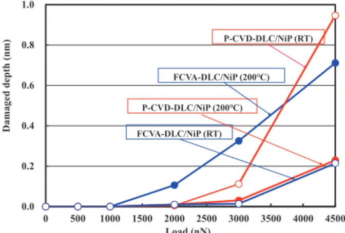
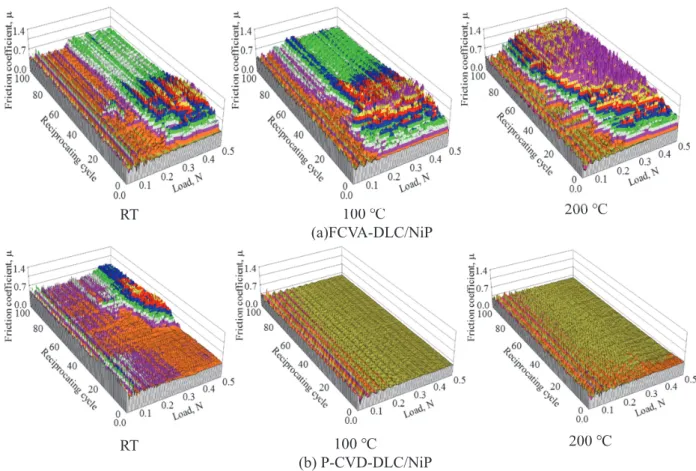
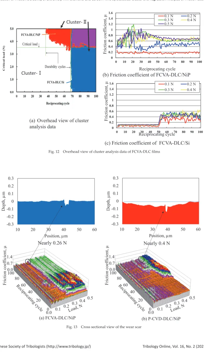
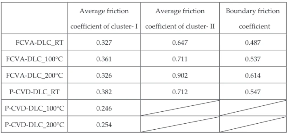
(5) Evaluation of Friction Durability of Extremely Thin Diamond-Like Carbon Films by Statistical Cluster and Regression Analyses of Friction Coefficient temperature, the force of the FCVA-DLC film on NiP is low at low load, and then increases sharply when the load reaches 3000 nN. The force of the P-CVD-DLC film on NiP also increases rapidly from 4500 nN. On Si, the force of the FCVA-DLC film is low and stable at room temperature in air, while that of the P-CVD-DLC film is slightly higher and also stable. At 200°C, the friction forces of the FCVA-DLC film on both substrates in vacuum are very high and increase rapidly with load, as shown in Fig. 8. In contrast, the friction force of the P-CVDDLC film on both substrates is lower at higher temperature than at room temperature because of the higher lubricity at higher temperature. However, at high load (4500 nN), the large deformation of the NiP substrate means that sliding can damage the P-CVD-DLC film. The effect of the applied load on the wear depth after the nanofriction tests at room temperature and 200°C on NiP is shown in Fig. 9. The wear depth of the FCVA-DLC film at room temperature was very shallow because of its high hardness. The film remained even after sliding of the tip, resulting in a low friction force. In contrast, the wear depth at 200°C was very deep at loads greater than 2000 nN. In the FCVA-DLC films, which are hydrogen-free, the adsorbate site and the surrounding hydrocarbon materials are adsorbed strongly. However, at high temperatures in vacuum, the adsorbate is removed by sliding. Therefore, the rapid increases of friction and wear for the FCVADLC film are caused by film degradation. For the P-CVD-DLC film at 200°C, a wear scar is hardly observed until a load of 3000 nN is reached; the wear depth increases to 0.2 nm at 4500 nN. At room temperature, the wear depth increases to 1.0 nm at 4500 nN. At this high load, the P-CVD-DLC film on NiP was removed because of plastic deformation. These results demonstrate the correlation between friction force and wear depth. The load-dependence of the friction properties of the films was more pronounced on NiP than on Si. In particular, there was substantial deterioration of the hard and brittle FCVA-DLC film at high temperature because of the large deformation of the soft NiP substrate under friction. This, in turn, reduced the durability of the DLC film. The friction force of the P-CVD-DLC films was low at 100 and 200°C. This result is consistent with the low wear rate of these films observed in the nanofriction tests at 100 and 200°C. We consider that at high temperature, the tribochemical products from these hydrogen-containing DLC films work as a lubricating layer [9]; the increase in the friction force and wear of the P-CVD-DLC film at 4500 nN at room temperature is attributable to the large deformation of the NiP substrate.. 3.2 Friction and durability properties 3.2.1 Dependence of the friction coefficient on the substrate material The dependence of the friction coefficients on the load and number of reciprocating cycles for the films on NiP is shown in Fig. 10. The friction coefficient of the FCVA-DLC film increased rapidly above a critical load after a few cycles (Fig. 10(a)). At room temperature, at loads above approximately 0.28 N, the friction coefficient increased after only two reciprocating cycles, owing to film degradation. Degradation was defined as the state in which the friction coefficient increased and the lubricating effect of the DLC film was reduced. At 100°C, the friction coefficient increased after two cycles at loads above 0.15 N. At 200°C, the friction coefficient increased after two cycles above a load of approximately 0.15 N. Below these critical loads, the friction coefficient does not increase with increasing cycle number. Figure 10(b) shows the dependence of the friction coefficient on load and number of reciprocating cycles of the P-CVD-DLC film on NiP. In general, the friction is lower and more stable than seen with the FCVA-DLC film. At room temperature, the friction coefficient increases after 38 reciprocating cycles at loads above 0.4 N. However, at 100 and 200°C, the friction coefficient is low and does not undergo any abrupt increase during the 100 reciprocating cycles of the test. Thus, the durability of the P-CVD-DLC film is greater than that of the FCVA-DLC film at all temperatures. The friction coefficients of the two films on Si (Fig. 11) are lower than on NiP. At room temperature, the friction coefficient of the FCVA-DLC film (Fig. 11(a)) on Si is low, and no rapid increase with increasing cycle number was observed. However, at 100°C, the friction coefficient rapidly increased after around 52 cycles at all loads. At 200°C, it increased after two cycles, which was similar to the behavior on NiP. Thus, on both surfaces, the durability of the FCVA-DLC film decreases at high temperature. At high temperature on Si, the P-CVD-DLC film (Fig. 11(b)) shows greater durability than the FCVA-DLC film does. At 100 and 200°C, the friction coefficient of the P-CVDDLC film on Si is low, and does not rapidly increase over the 100 reciprocating cycles of the test.. Damaged depth (nm). 1.0 P-CVD-DLC/NiP (RT). 0.8. FCVA-DLC/NiP (200℃). 0.6. P-CVD-DLC/NiP (200℃). 0.4. FCVA-DLC/NiP (RT). 0.2. 0.0. 0. 500. Fig. 9. 1000. 1500. 2000 2500 Load (nN). 3000. 3500. 4000. 4500. Damage depth dependence on load. Japanese Society of Tribologists (http://www.tribology.jp/). 9. 3.2.2 Durability evaluation To evaluate the durability of these DLC films, the dependence of their friction coefficients on load and reciprocating cycle number at various temperatures were evaluated by statistical cluster analysis. Figure 12(a) shows a representative overhead view of the cluster analysis data. Cluster-I represents the low-friction region in which lubrication of the film was effective, and cluster-II represents the highfriction region where this lubricating effect was lost. The critical load and durability (i.e., the number of reciprocating cycles over which the friction was stable) can be evaluated. When these conditions are exceeded, the effect of the DLC film is lost and the friction coefficient changes from cluster-I to cluster-II. Thus, the friction durability can be evaluated from the boundary conditions of these clusters. At room temperature, the friction coefficient of the FCVADLC film on NiP increased rapidly from the second cycle above 0.2 N owing to degradation of the film. Destruction appeared as substantial damage of the extremely thin DLC film, and penetrated deep into the substrate, as shown in Fig. 13. However, below these critical loads, the friction coefficient does not increase during cycling, as shown in Fig. 12(a) and (b). On Si, the friction coefficient of the FCVA-DLC film is stable at. Tribology Online, Vol. 16, No. 2 (2021) /117.
(6) Shojiro Miyake and Masatoshi Miyake. RT. 100 ℃ (a)FCVA-DLC/NiP. 200 ℃. RT. 100 ℃ (b) P-CVD-DLC/NiP. 200 ℃. Fig. 10. Friction properties of DLC films on NiP at various temperature. RT. 100 ℃ (a) FCVA-DLC/Si. 200 ℃. 200 ℃. 100 ℃ (b) P-CVD-DLC/Si. Room temp Fig. 11. Friction properties of DLC films on Si at various temperature. Japanese Society of Tribologists (http://www.tribology.jp/). Tribology Online, Vol. 16, No. 2 (2021) /118.
(7) Friction coefficient, . Evaluation of Friction Durability of Extremely Thin Diamond-Like Carbon Films by Statistical Cluster and Regression Analyses of Friction Coefficient. Cluster‐Ⅱ. 1.6. 0.1 N 0.3 N 0.5 N. 1.4 1.2. 0.2 N 0.4 N. 1 0.8 0.6 0.4 0.2 0. 0. 10. 20. 30. 40. 50. 60. 70. 80. 90. 100. Reciprocating cycle. Cluster‐Ⅰ. Friction coefficient, . (b) Friction coefficient of FCVA-DLC/NiP. (a) Overhead view of cluster analysis data. 1.6. 0.1 N 0.3 N. 1.4 1.2. 0.2 N 0.4 N. 1 0.8 0.6 0.4 0.2 0. 0. 10. 20. 30. 40. 50. 60. 70. Reciprocating cycle. 80. 90. 100. (c) Friction coefficient of FCVA-DLC/Si Overhead view of cluster analysis data of FCVA-DLC films. 0.3. 0.3. 0.2. 0.2. 0.1. 0.1. Depth, m. Depth, m. Fig. 12. 0 -0.1. 10. 20. 30 40 Position, m. 50. -0.3. 60. Nearly 0.26 N. Friction coefficient, . Friction coefficient, . 1.4 0.7 0.0 100. -0.1 -0.2. -0.2 -0.3. 0. 1.4 0.7 0.0 100. 80 60. 10. 20. 30 40 Position, m. 50. Nearly 0.4 N. 80 60 40. 40 20. 0.3. 0.2 0 0.1 0.0 (a) FCVA-DLC/NiP. Fig. 13. 0.4. 0.5. 60. 20. 0.3. 0.2 0 0.1 0.0 (b) P-CVD-DLC/NiP. 0.4. 0.5. Cross sectional view of the wear scar. Japanese Society of Tribologists (http://www.tribology.jp/). Tribology Online, Vol. 16, No. 2 (2021) /119.
(8) Shojiro Miyake and Masatoshi Miyake first, but increases after a similar number of reciprocating cycles (i.e., ~52) at all loads, as shown in Fig. 12(a) and (c). Even at 0.1 N load, the friction coefficient increases. The destruction of the DLC film occurred at regions of high load, then expanded from the high load areas to the low load areas. The average friction coefficients of the films were higher on NiP (Table 2) than on Si (Table 3). The durability of the FCVADLC film was low at room temperature, reducing even further at 100°C (Figs. 10 and 11). We consider this decrease in friction durability at high temperature to be due to degradation of this hard and brittle film, as was observed in the nanofriction test. In cluster-II, the friction coefficients on NiP are higher than those on Si, as was the case in cluster-I. In cluster-II, because of film degradation, the substrate had a substantial effect on the friction coefficient. The friction coefficient of the P-CVD-DLC film on Si is low (0.05–0.13), decreasing with increasing temperature on both substrates. Above the critical load, the durability of both films on NiP is lower than on Si; however, below this critical load, the durability is similar on both substrates. At low load, the contact stress is low because of the low elastic modulus of NiP. Therefore, the films are barely damaged, and show high durability. 3.2.3 Deterioration mechanism We performed regression analysis of the dependence of the friction coefficient on load and reciprocating cycle number in cluster-I [17]. The empirical formula of the friction coefficient Table 2. Average friction coefficient of cluster- I and - II for NiP Average friction . . was defined as µ = aL bN c (µ: friction coefficient; L: load; N: number of reciprocating cycles; a, b, c: constants). Both the load dependence of the friction coefficient and the dependence of the friction coefficient on relative velocity can be expressed as an exponential function [32, 33], and we have previously evaluated exponential power indices by multiple regression analysis [34]. In this study, the friction coefficients of the extremely thin DLC films increase exponentially as the DLC film eventually becomes ineffective at higher loads or longer cycles. Therefore, to evaluate the degradation process at various loads, we expressed the friction coefficient as an exponential function of the number of sliding cycles. The results of regression analysis for the FCVA-DLC film on NiP are shown in Table 4. The coefficient of each parameter, standard deviation, and p-values are given. A p-value less than 0.05 is considered statistically significant. The friction coefficient increases with load, and the power index, b, increases from 0.27 to 0.57 with temperature. Moreover, at higher temperature, greater load dependence was observed. At high temperature and high load, the lubricity of the FCVA-DLC film deteriorates, the friction coefficient increases, and therefore the durability decreases. Larger b shows that there was a rapid increase in friction coefficient at high load on NiP, which we attributed to film degradation. The load dependence b of the friction coefficient of the FCVA-DLC film on NiP was especially large at high temperature. This hard and brittle film partially fractured during the sliding test owing to stress concentration after deformation of the softer NiP substrate. For the P-CVDDLC film (Table 5), the value of b is small (0.04–0.07), therefore. Average friction . Boundary friction . coefficient of cluster‐ I coefficient of cluster‐ II . coefficient . FCVA‐DLC_RT . 0.327 . 0.647 . 0.487 . FCVA‐DLC_100°C . 0.361 . 0.711 . 0.537 . FCVA‐DLC_200°C . 0.326 . 0.902 . 0.614 . P‐CVD‐DLC_RT . 0.382 . 0.712 . 0.547 . P‐CVD‐DLC_100°C . 0.246 . . . P‐CVD‐DLC_200°C . 0.254 . . . Table 3. Average friction coefficient of cluster- I and - II for Si Average friction . Average friction . Boundary friction . coefficient of cluster‐ I . coefficient of cluster‐ II . coefficient . FCVA‐DLC__RT . 0.171 . . . FCVA‐DLC_100°C . 0.106 . 0.451 . 0.279 . FCVA‐DLC_200°C . 0.278 . 0.436 . 0.357 . P‐CVD‐DLC_RT . 0.185 . . . P‐CVD‐DLC_100°C . 0.139 . . . P‐CVD‐DLC_200°C . 0.046 . . . . Japanese Society of Tribologists (http://www.tribology.jp/). Tribology Online, Vol. 16, No. 2 (2021) /120.
(9) Evaluation of Friction Durability of Extremely Thin Diamond-Like Carbon Films by Statistical Cluster and Regression Analyses of Friction Coefficient Table 4. Regression analysis of friction coefficient dependence on load and number of cycles for FCVA-DLC/NiP. RT. µ=aLbNc RT . Coefficient . Standard deviation . p Value . a . 0.4586 . 0.0083 . 2E‐16 . b(L) . 0.2706 . 0.0090 . 2E‐16 . c(N) . 0.0480 . 0.0038 . 2E‐16 . 100°C . Coefficient . Standard deviation . p Value . a . 0.5694 . 0.0108 . 2E‐16 . b(L) . 0.3253 . 0.0097 . 2E‐16 . c(N) . 0.0601 . 0.0045 . 2E‐16 . 200°C (100) . Coefficient . Table 5 Regression analysis of friction coefficient dependence on load and number of cycles for P-CVD-DLC/NiP. Standard deviation . p Value . a . 0.6765 . 0.0140 . 2E‐16 . b(L) . 0.5793 . 0.0107 . 2E‐16 . c(N) . 0.1092 . 0.0052 . 2E‐16 . the friction coefficient has a weaker dependence on load than was seen for the FCVA-DLC film and was stable at high temperature because of its superior lubricity. Index c, which relates the friction coefficient to the number of reciprocating cycles, ranged from 0.05–0.11 for the FCVADLC film on NiP, as shown in Table 4. At high temperature, the friction coefficient has a large dependence on reciprocating cycle number, indicated by the higher value of c. In contrast, c of the P-CVD-DLC film is very small or negative, as shown in Table 5. Thus, the friction coefficient of this film is stable or decreases with increasing reciprocating cycles. The results from the regression analysis for the FCVADLC film on Si are shown in Table 6. The friction coefficient increases with load, and b increases from 0.06 to 0.233 with increasing temperature; this range of b values is lower than that of the FCVA-DLC film on NiP but shows a similar trend with temperature. As shown earlier in Fig. 10(a), at 200°C (b = 0.233), the surface lubricity decreases and the friction coefficient increases with load. In contrast, index c of the P-CVD-DLC film on Si is very small or negative, as shown in Table 7, indicating higher durability. Moreover, the friction coefficient is very low (0.04) at low load. The decrease in durability of FCVADLC films at high temperature was due to degradation of this hard, brittle film. This led to fracture and disconnection of the lubricative surface adsorption layer. In contrast, the decrease in friction coefficient of the P-CVD-DLC film at high temperature is related to the tribochemical hydrocarbon products that are readily produced from this film at high temperature. Therefore,. Japanese Society of Tribologists (http://www.tribology.jp/). Coefficient. Standard deviation. p Value. a. 0.3952. 0.0041. 2E-16. b(L). 0.0448. 0.0043. 2E-16. c(N). 0.0097. 0.0025. 0.000121. Coefficient . Standard deviation . p Value . 100°C a . 0.3003 . 0.0035 . 2E‐16 . b(L) . 0.0634 . 0.0045 . 2E‐16 . c(N) . ‐0.0303 . 0.0027 . 2E‐16 . 200°C (100) . Coefficient . Standard deviation . p Value . a . 0.3854 . 0.0037 . 2E‐16 . b(L) . 0.0697 . 0.0040 . 2E‐16 . c(N) . ‐0.0882 . 0.0022 . 2E‐16 . low friction and better durability at high temperature can be obtained for the P-CVD-DLC film. 3.2.4 Damage-formation mechanism The cross-section profiles of the wear scars after the sliding test (at loads of approximately 0.26 and 0.4 N for the FCVA-DLC and P-CVD-DLC films, respectively) are shown in Fig. 13, along with the friction maps of the two films on NiP. The appearance of wear scars corresponds to the increase of the friction coefficient. Destruction was determined as when significant damage of the extremely thin DLC film allowed the scar to penetrate deep into the substrate, as shown in Fig. 13. The wear profile of the more durable P-CVD-DLC film is smaller than that of the FCVA-DLC film. However, macroscopic profile change produced by plastic deformation of P-CVD-DLC/NiP is observed as changes in the base line in the area surrounding the wear scar, particularly in Fig. 13(b). In contrast, the area surrounding the scar in the FCVA-DLC film is less deformed (Fig. 13(a)). The P-CVD-DLC film is softer than the FCVA-DLC film and therefore has a lower contact pressure [8]. At room temperature, the P-CVD-DLC film on NiP withstood higher loads and was deformed by ball sliding. Because NiP has a lower hardness and smaller elastic modulus than Si does, it can easily undergo plastic and elastic deformation with increasing load. Therefore, at high load, the hard and brittle FCVA-DLC film is more easily fractured on NiP than on Si. We deduce that this is because of the larger deformation of the NiP substrate which was caused by stress distortion as a result of loading and heating. At high temperature, the friction coefficient of the FCVADLC film on both substrates is relatively high, and the. Tribology Online, Vol. 16, No. 2 (2021) /121.
(10) Shojiro Miyake and Masatoshi Miyake Table 6. Regression analysis of friction coefficient dependence on load and number of cycles for FCVA-DLC/Si. RT . Coefficient . Standard deviation . Table 7 Regression analysis of friction coefficient dependence on load and number of cycles for P-CVD-DLC/Si. p Value . RT . Coefficient . Standard deviation . p Value . a . 0.156396 . 0.000642 . 2E‐16 . a . 0.164716 . 0.000686 . 2E‐16 . b(L) . 0.097363 . 0.001406 . 2E‐16 . b(L) . ‐0.02324 . 0.001417 . 2E‐16 . c(N) . 0.061904 . 0.000945 . 2E‐16 . c(N) . 0.022182 . 0.000957 . 2E‐16 . 100°C . Coefficient . Standard deviation . p Value . 100°C . Coefficient . Standard deviation . p Value . a . 0.172669 . 0.001228 . 2E‐16 . a . 0.090733 . 0.001562 . 2E‐16 . b(L) . 0.110561 . 0.002718 . 2E‐16 . b(L) . 0.052758 . 0.006388 . 2E‐16 . c(N) . ‐0.01579 . 0.001626 . 2E‐16 . c(N) . 0.07522 . 0.004641 . 2E‐16 . 200°C (100) . Coefficient . Standard deviation . p Value . 200°C (100) . Coefficient . Standard deviation . p Value . a . 0.387033 . 0.005673 . 2E‐16 . a . 0.463296 . 0.018837 . 2E‐16 . b(L) . 0.233721 . 0.005318 . 2E‐16 . b(L) . 1.570343 . 0.031525 . 2E‐16 . c(N) . 0.015815 . 0.002953 . 9.04E‐08 . c(N) . ‐0.05061 . 0.007653 . 3.97E‐11 . durability cycle and critical load are lower than those at room temperature. The hard and brittle FCVA-DLC film is easily fractured by stress caused by deformation of the substrate. On the softer NiP, deformation increases at a lower load than on Si owing to the overlap of sliding and thermal deformation of the NiP substrate. In contrast to the FCVA-DLC film, the friction coefficient of the P-CVD-DLC film is relatively high at room temperature; however, the friction coefficient decreases at high temperature, associated with an increase in durability and critical load. At high load, the P-CVD-DLC film was degraded on softer NiP. However, the friction coefficient on both substrates decreased at high temperature. We attribute this to the lubricating effect of the products of a tribochemical reaction of the hydrogencontaining P-CVD-DLC film at high temperature. For a P-CVD-DLC film deposited by a similar P-CVD method, we have previously evaluated the tribochemical evidence with FTIR (Fourier transform infrared spectroscopy), SEM (scanning electron microscopy), and TDS (thermal desorption spectroscopy), among other techniques, to confirm the formation of the hydrocarbon transfer layer [29-31]. Subsequently, our papers about the hydrocarbon transfer layer have been cited in many other studies, including [35-39]. These hydrocarbon transfer layers formed by tribochemical reaction have been discussed as the basis for the superlubricity of hydrogen-containing DLC films, and explain why these films show low friction and better durability at high temperature. These results and explanation are consistent with the superior nanofriction and wear properties of the P-CVD-DLC film at high temperature. In summary, the P-CVD-DLC film has greater durability at low load and high temperature on NiP.. Japanese Society of Tribologists (http://www.tribology.jp/). 4 Conclusions To better understand the durability, we analyzed the tribological properties of extremely thin DLC films deposited by FCVA and P-CVD on NiP and Si substrates using statistical methods. From our results, we draw the following conclusions: (1) The measured nanoindentation hardnesses and elastic moduli of the DLC films were lower when the films were deposited on NiP than when they were deposited on Si. Using atomic force microscopy, we evaluated the dependence of the nanofriction and wear properties on load and temperature. There was a rapid increase in friction force at high load on NiP, which we attributed to film degradation. Degradation was defined as a state in which the friction coefficient increases and the lubricating effect of the DLC film is reduced. The load dependence of the friction coefficient of the FCVA-DLC film on NiP was especially strong at high temperature. This hard and brittle film partially fractured during the sliding test owing to stress concentration after deformation of the softer NiP substrate. In contrast, the friction coefficient of the P-CVDDLC film had a lower dependence on load and was stable at high temperature because of its superior lubricity. (2) The dependences of the friction maps on the load and number of reciprocating cycles were evaluated by load increase-and-decrease friction tests. The critical load and durability were then evaluated using statistical cluster analysis. The durability of the DLC film was defined as when the friction coefficient increased rapidly beyond a certain boundary value. At high temperature, the FCVADLC films on NiP had lower friction durability than did the. Tribology Online, Vol. 16, No. 2 (2021) /122.
(11) Evaluation of Friction Durability of Extremely Thin Diamond-Like Carbon Films by Statistical Cluster and Regression Analyses of Friction Coefficient P-CVD-DLC films. The friction coefficient of both films on NiP was higher and the durability was lower than on Si at high load and temperature. The durability of the P-CVDDLC film on NiP was high below the critical load. At lower load, the contact stress was low because of the low hardness and elastic modulus of NiP. Therefore, there was little damage to this DLC film. (3) The friction coefficient was deduced to be an exponential function of load and reciprocating cycles, and the degradation mechanism of each film was clarified by regression analysis in the low-friction region (Cluster-I). We concluded that the decrease in durability of FCVA-DLC films at high temperature was due to degradation of this hard, brittle film. This led to fracture and disconnection of the lubricative surface adsorption layer. In contrast, we explained the decrease in friction coefficient of the P-CVD-DLC film with increasing temperature in terms of the tribochemical hydrocarbon products that are easily produced from this film at high temperature. Therefore, low friction and better durability at high temperature can be obtained for this film; this is evident in the superior nanofriction and wear properties of the P-CVD-DLC film at high temperature.. Properties of B-C-N Extremely Thin Protective Films Deposited on Plasma Pretreated Magnetic Layers,” Surf. Coat. Technol., 195, 2-3, 2005, 214-226. [11] Miyake, S., Saito, T., Wang, M. and Watanabe, S., “Tribological Properties of Extremely Thin Protective Carbon Nitride Films Deposited on Magnetic Discs by Complex Treatment,” Proc. IMechE J. Engineering Tribology, 220, 2006, 587-595. [12] Yasui, N., Inaba, H. and Furusawa, K., “Characterization of Head Overcoat for 1 Tb/in2 Magnetic Recording,” IEEE Magn. Soc., 45, 2009, 805-809. [13] Marchon, B., Pitchford, T., Hsia, Y. T. and Gangopadhyay, S., “The Head-Disk Interface Roadmap to an Areal Density of Tbit/in2,” Adv. Tribol., 2013, 521086. [14] Miyake, S., Inagaki, J. and Miyake, M., “Dependence of the Friction Durability of Extremely Thin Diamond-Like Carbon Films on Film Thickness,” Wear, 356-357, 2016, 66-76. [15] Xu, S., Tay, B. K., Tan, H. S., Zhong, L.,Tu, Y. Q., Silva, S. R. P. and Milne, W. I., “Properties of Carbon Ion Deposited Tetrahedral Amorphous Carbon Films as a Function of Ion Energy,” J. Appl. Phys., 79, 9, 1996, 7234-7240. [16] Lemoine, P., Quinn, J. P., Maguire, P. and McLaughlin, J. A., “Comparing Hardness and Wear Data for Tetrahedral Amorphous Carbon and Hydrogenated Amorphous Carbon Thin Films,” Wear, 257, 5-6, 2004, 509-522.. Acknowledgements This research was performed with the experimental help of graduate students at Nippon Institute of Technology. Samples were partly supplied by the Storage Research Consortium. We thank Edanz Group (https://en-author-services.edanz.com/ac) for editing a draft of this manuscript.. [17] Miyake, S., Shindo, T. and Miyake, M., “Regression Analysis of the Effect of Bias Voltage on Nano- and Macrotribological Properties of Diamond-Like Carbon Films Deposited by a Filtered Cathodic Vacuum Arc Ion-Plating Method,” J. Nanomaterial., 2014, 657619. [18] Beakea, B. D., Daviesa, M. I., Liskiewiczc, T. W., Vishnyakovb, V. M. and Goodesa, S. R., “Nano-Scratch, Nanoindentation and Fretting Tests of 5–80 nm ta-C Films on Si (100),” Wear, 301, 2013, 575-582. [19] Katayama, H., Sawamura, S., Ogimoto, Y., Nakajima, J., Kojima, K.. References [1] Bhushan, B., “Tribology and Mechanics of Magnetic Storage Devices,” Springer-Verlag, New York, 1990. [2] Miyake, S. and Wang, M., “Nanotribology of Magnetic Disks,”. and Ohta, K., “New Magnetic Recording Method Using Laser Assist Read/Write Technologies,” J. Magn. Soc. Jpn., 23, 1999, 233-236. [20] Saga, H., Nemoto, H., Sukeda, H. and Takahashi, M., “New Recording Method Combining Thermo-Magnetic Writing and Flux Detection,” Jpn. J. Appl. Phys., 3B, 1999, 1839-1840.. Edited by H. S. Nalwa, Encyclopedia of Nanoscience and. [21] Pathem, B. K., Guo, X. C., Rose, F., Wang, N., Komvopoulos, K.,. Nanotechnology, American Scientific Publishers, Valencia, CA, 19, 3,. Schreck, E. and Marchon, B., “Carbon Overcoat Oxidation in Heat-. 2011, 399-451.. Assisted Magnetic Recording,” IEEE Trans. Magn., 49, 2013, 3721-. [3] Miyake, S. and Kaneko, R., “Microtribological Properties and Potential Applications of Hard, Lubricating Coatings,” Thin Solid Films, 212, 1-2, 1992, 256-261. [4] Yamamoto, T., Toyoguchi, T. and Honda, F., “Ultrathin Amorphous C:H Overcoats by pCVD on Thin Film Media,” IEEE Trans. Magn., 36, 2000, 115-119. [5] Robertson, J., “Ultrathin Carbon Coatings for Magnetic Storage Technology,” Thin Solid Films, 383, 2001, 81-88.. 3724. [22] Wang, N. and Komvopoulos, K., “Thermal Stability of Ultrathin Amorphous Carbon Films for Energy-Assisted Magnetic Recording,” IEEE Trans. Magn., 47, 2011, 2277-2282. [23] Miyake, S., Kawasaki, S. and Yamazaki, S., “Nanotribology Properties of Extremely Thin Diamond-Like Carbon Films at High Temperatures with and without Vibration,” Wear, 300, 2013, 189199.. [6] Yamamoto, T., Hyodo, H., Tsuchitani, S. and Kaneko, R.,. [24] Miyake, S. and Yamazaki, S., “Evaluation of Protuberance and. “Ultrathin Amorphous Carbon Overcoats by Filtered Cathodic Arc. Groove Formation in Extremely Thin DLC Films on Si Substrates. Deposition,” IEEE Trans. Magn., 39, 5, 2003, 2201-2204.. Due to Diamond Tip Sliding by Atomic Force Microscopy,” Wear,. [7] Hyodo, H., Yamamoto, T. and Toyoguchi, T., “Properties of Tetrahedral Amorphous Carbon Film by Filtered Cathodic Arc Deposition for Disk Overcoat,” IEEE Trans. Magn., 37, 4, 2001, 17891791. [8] Miyake, S., Kurosaka, W. and Oshimoto, K., “Nanometer-Scale Mechanical Properties of Extremely Thin Diamondlike Carbon Films,” Tribology - Materials, Surfaces & Interfaces, 3, 4, 2009, 158164. [9] Miyake, S., Suzuki, S. and Miyake, M., “Friction Durability of Extremely Thin Diamond-Like Carbon Films at High Temperature,” Materials, 10, 2017, 159. [10] Miyake, S., Wang, M., Saitoh, T. and Watanabe, S., “Microtribological. Japanese Society of Tribologists (http://www.tribology.jp/). 318, 2014, 135-144. [25] Miyake, S. and Yamazaki, S., “Nanoscratch Properties of Extremely Thin Diamond-Like Carbon Films,” Wear, 305, 2013, 69-77. [26] Miyake, S., “Atomic-Scale Wear Properties of Muscovite Mica Evaluated by Scanning Probe Microscopy,” Appl. Phys. Lett., 65, 8, 1994, 980-982. [27] Miyake, S., “1 nm Deep Mechanical Processing of Muscovite Mica by Atomic Force Microscopy,” Appl. Phys. Lett., 67, 20, 1995, 2925. [28] The R Project for Statistical Computing, Available Online: https:// www.r-project.org/ (accessed on10 July 2015). [29] Miyake, S., Takahashi, S., Watanabe, I. and Yoshihara, H., “Friction and Wear Behavior of Hard Carbon Films,” ASLE Trans., 30, 1, 1987,. Tribology Online, Vol. 16, No. 2 (2021) /123.
(12) Shojiro Miyake and Masatoshi Miyake 121-127.. Japanese).. [30] Sugimoto, I. and Miyake, S., “Oriented Hydrocarbons Transferred. [35] Donnel, C., Fontaine, J., Grill, A. and Mogne, T. L., “The Role of. from a High Performance Lubricative Amorphous C:H:Si Film. Hydrogen on the Friction Mechanism of Diamond-Like Carbon. during Sliding in a Vacuum,” Appl. Phys. Lett., 56, 19, 1990, 1868.. Films,” Tribology Letters, 9, 3-4, 2000, 137-142.. [31] Miyake, S., “Tribological Properties of Hard Carbon Films:. [36] Erdemir, A., “The Role of Hydrogen in Tribological Properties of. Extremely Low Friction Mechanism of Amorphous Hydrogenated. Diamond-Like Carbon films,” Surf. Coat. Technol., 146-147, 2001,. Carbon Films and Amorphous Hydrogenated SiC Films in Vacuum,” Surface and Coatings Technology, 54-55, 1993, 563-569. [32] Pascoe, M. W. and Tabor, D., “The Friction and Deformation of Polymers,” Proc. of the Royal Society of London A235, 1201, 1956, 210-224. [33] Kawasaki, K., “Friction of Plastic,” Trans. Jpn. Soc. Mech. Eng., 1962, 28, 196, 1707-1712 (in Japanese). [34] Miyake, S. and Katayama, Y., “The Sliding Friction of Thermoplastic Polymers,” J. Jpn. Soc. Lubr. Eng. (Junkatsu), 17, 2, 1972, 83-89 (in. 292-297. [37] Heimberg, J. A., Wahl, K. J., Singer, I. L. and Erdemir, A., “Superlow Friction Behavior of Diamond-Like Carbon Coatings: Time and Speed Effects,” Appl. Phys. Lett., 78, 2001, 2449-2451. [38] Chen, X. and Li, J., “Superlubricity of Carbon Nanostructures,” Carbon, 158, 2020, 1-23. [39] Erdemir, A. and Eryilmaz, O., “Achieving Superlubricity in DLC Films by Controlling Bulk, Surface, and Tribochemistry,” Friction, 2, 2, 2014, 140-155.. This paper is licensed under the Creative Commons Attribution-NonCommercial-NoDerivatives 4.0 International (CC BY-NC-ND 4.0) International License. This allows users to copy and distribute the paper, only upon conditions that (i) users do not copy or distribute such paper for commercial purposes, (ii) users do not change, modify or edit such paper in any way, (iii) users give appropriate credit (with a link to the formal publication through the relevant DOI (Digital Object Identifier)) and provide a link to this license, and (iv) users acknowledge and agree that users and their use of such paper are not connected with, or sponsored, endorsed, or granted official status by the Licensor (i.e. Japanese Society of Tribologists). To view this license, go to https://creativecommons.org/licenses/by-nc-nd/4.0/. Be noted that the third-party materials in this article are not included in the Creative Commons license, if indicated on the material's credit line. The users must obtain the permission of the copyright holder and use the third-party materials in accordance with the rule specified by the copyright holder.. Japanese Society of Tribologists (http://www.tribology.jp/). Tribology Online, Vol. 16, No. 2 (2021) /124.
(13)
図
+5

関連したドキュメント
In the experimental part, the path shape of a yarn contacting with the toric surface of twisting disk was photographed and simultaneously the yarn tension was measured under
Fig.7 Yam path on a disk surface In case the yarn is rotating 27... Yam path on a disk
Keywords: homology representation, permutation module, Andre permutations, simsun permutation, tangent and Genocchi
Standard domino tableaux have already been considered by many authors [33], [6], [34], [8], [1], but, to the best of our knowledge, the expression of the
H ernández , Positive and free boundary solutions to singular nonlinear elliptic problems with absorption; An overview and open problems, in: Proceedings of the Variational
It is a new contribution to the Mathematical Theory of Contact Mechanics, MTCM, which has seen considerable progress, especially since the beginning of this century, in
Keywords: Convex order ; Fréchet distribution ; Median ; Mittag-Leffler distribution ; Mittag- Leffler function ; Stable distribution ; Stochastic order.. AMS MSC 2010: Primary 60E05
Theorem 2 If F is a compact oriented surface with boundary then the Yang- Mills measure of a skein corresponding to a blackboard framed colored link can be computed using formula
