1. Introduction
Titanium and its alloy have become important medical materials [1-6]
for the human body hard organization to repair and/or replace, because they provides smaller elastic modulus close to the bone tissue of body, good chemical stability, corrosion resistance, and excellent biological compatibility, in addition to relatively low costs for fabrication.
The hydroxyapatite (HA) is an inorganic material which can be chemically connected with the bone tissue. It has been thought as the best bioceramics in biological compatibility at present[7]
.
The hydroxyapatite coating can be deposited directly on the surface of titanium alloy through such processes as laser melting or sol-gel method,but theses hydroxyapatite decompose easily and the integraty with the substrate is poor. Extensive application of these processes has been restricted[8, 9]
.
Micro-arc oxidation (MAO) is a novel technique[10, 11]
to deposit ceramic coatings on the surface of metals and alloys. The ceramic coating formed by MAO can be adhered tightly to its substrate, which is a most important
characteristic.
By means of the MAO technique, high quality ceramic coatings with high micro-hardness, high adhesion, high strength and high wear resistance can be obtained. The coatings can be used in many application fields, such as automotive, aerospace, textile engineering and medicine, etc.
MAO is a multifactor-controlled process. The qualities of MAO ceramic coating are affected by technical parameters like composition of electrolyte, temperature of electrolyte, alloy composition, voltage, current density, handling time, etc. High quality coatings can only be formed through the optimization of deposition parameters.
The effect of the electrolyte composition on morphologies and structures of ceramic coating on TC4 alloy prepared by MAO has been investigated in this work. 2. Experimental details
The substrates of TC4 (Ti6-Al4-V) titanium alloy with 30 mm in length and 20 mm in width and 1 mm thickness were cleaned with acetone in a ultrasonic cleaner and
Study on Morphologies and Structures of Ceramic Coating Prepared
by Micro-Arc Oxidation on TC4 Alloy in Different Electrolytes
Li Pengfei*
(College of Materials Science and Engineering, Inner Mongolia University of Technology, Huhhot, 010051, CHINA) Abstract: In this work, the effects of concentration and mixture ratio of Ca(CH3COO)2•H2O and Na5P3O10 in electrolyte on surface morphology, and phase structure of ceramic coating prepared by micro-arc oxidation (MAO) on TC4 titanium alloy were studied. A suitable formula of electrolyte for bio-modification of titanium by MAO was obtained, namely, Ca(CH3COO)2•H2O 20g/L and Na5P3O10 9.3g/L. Using this electrolyte with appropriate process conditions, the ceramic coating was prepared with porous structure and combined well with the substrate. Scanning electron microscope (SEM) equipped with the energy dispersive spectrometry (EDS) was used for observation and evaluation of the morphology. The pores distributed equably on the surface of ceramic coating and the size of pores was in micron order. The ceramic coating was composed of titanium dioxide in different crystal types which have been characterized by the X-ray diffraction (XRD). The anatase titanium dioxide was a major component.
Key words: Ceramic Coating; Micro-Arc Oxidation; TC4; Electrolyte
*The author comes from Inner Mongolia University of Technology who is training at the research group of Professor Nobuo Ishizawa in the CRL under the auspices of Japan Bank for International Cooperation (JBIC) from 6 October 2008 to 28 March 2009.
rinsed with water to remove the mechanical contamination and grease. The electrolyte was composed of the analytical reagent grade Ca(CH3COO)2•H2O,
Na5P3O10, Na2SiO3•9H2O, and deionized water.
The special MAO equipment with adjustable frequency and voltage was used for the MAO process, consisting of a stainless steel tank and a high voltage asymmetric ac power supply. One output of the power supply was connected to the stainless steel tank; the other was connected to the sample immersed in electrolyte. Figure 1 shows an illustration of the special MAO equipment system.
The process parameters adopted in the experiment are; anodic voltage 460 V, cathodic voltage 160 V, frequency 800 Hz, handling time 20 minutes. The electrolyte temperature was controlled between 15˚C∼30˚C during the treatment by cooling the electrolyte solution with a heat exchanger.
The concentration of Na2SiO3•9H2O was constant,
while the ratio of Ca(CH3COO)2•H2O and Na5P3O10 was
adjusted in each electrolyte. Formulas of the electrolytes are given in Table 1.
The samples treated by MAO were cleaned with anhydrous alcohol and deionized water in a ultrasonic cleaner. Scanning electron microscope (SEM) equipped with energy dispersive spectrometry (EDS) was used for the observation and evaluation of the morphology of
ceramic coating formed on the TC4 alloy. The phase composition of the ceramic coating was characterized with X-ray diffraction (XRD).
3. Results & discussion
3.1. Effects of electrolytes on morphologies of ceramic coating
During MAO process, numerous micro-arc discharges occurred. When a micro-arc discharge is extinguished, it left a pore on the coating surface. Thus the MAO coatings usually have a porous surface layer, which originates in the high temperature treatments along discharge channels during MAO process.
The gray ceramic coating was prepared on the surface of samples by MAO. Some typical SEM micrographs of MAO ceramic coating formed on the samples in different electrolytes are shown in Figs. 2 and 3.
When the concentration of Ca(CH3COO)2•H2O is held
at 20g/L, we can see from Fig. 2 that the porosity of the ceramic coating increases with decreasing the Na5P3O10
concentration. The pore sizes range from several micrometers to less than one, and the average sizes of the samples are not larger than 5mm.
When the atomic ratio of Ca and P elements in the electrolyte was 3:1, the surface of the ceramic coating has partially appeared protuberant like a volcano shape as shown in Fig 2, 1-f.
When the atomic ratio of Ca and P elements is held at 1.5:1 in the electrolytes, the concentration of Ca(CH3COO)2•H2O and Na5P3O10 increases in each
electrolytes at the same time. The results show that thickness of ceramic coating formed in lower
Fig.1 Illustration of Micro-Arc Oxidation equipment system.
1. Power supply, 2. Sample, 3. Stainless steel tank, 4. Electrolyte, 5. Mixing device, 6. Valve.
Table 1. Formulas of electrolytes.
2-d 2-c 2-b 2-a 1-f 1-e 1-d 1-c 1-b 1-a serial number 40 30 20 10 20 20 20 20 20 20
Ca(CH3COO)2•H2O/g.L -1 18.7 14 9.3 4.7 4.7 7.0 9.3 10.8 12.7 14 Na5P3O10/g.L -1 1.5:1 1.5:1 1.5:1 1.5:1 3:1 2:1 1.5:1 1.3: 1 1.1:1 1:1 Ca/P (mol)
Fig.2 Surface morphologies of MAO coatings with different
concentration electrolyte was smaller than those in higher concentration electrolyte and the pores were flimsy as shown in Fig 3, 2-b. While the concentration of electrolytes was higher, the numbers of pore formed were lower, and the pore size became larger as shown in Fig 3, 2-d.
After comprehensive evaluation for the thickness and smoothness of the ceramic coatings, the porosity, the pore sizes and pore distribution at the surface, here we present a suitable formula of electrolyte, that is, the concentration of Ca(CH3COO)2•H2O is more than 20g/L and the atomic
ratio of Ca and P elements in the electrolyte is between 1.3:1 to 2:1.
3.2. Distribution of Ca and P in the ceramic coatings In order to make the titanium alloy be joined to the osteoblast, its surface has to possess excellent biological compatibility. The hydroxyapatite has been regarded as one of the best bioceramics in biological compatibility at present. The MAO ceramic coating containing higher content of Ca and P elements and the right atomic ratio have become advantageous conditions to cultivate hydroxyapatite.
Cross section microstructure of the sample and distribution of Ca and P elements in of the MAO ceramic
coating is shown in Fig. 4. The ceramic coating containing pores was tightly combined with the titanium alloy substrate. The Ca and P elements in the electrolyte reacted upon the MAO ceramic coating and the most was distributed near the surface of the ceramic coating.
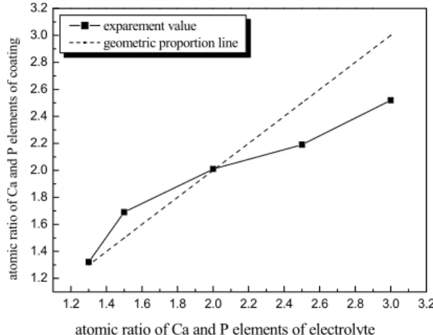
Figure 5 shows relationship of the atomic Ca/P ratios in ceramic coating and electrolyte when concentration of Ca(CH3COO)2•H2O is held at 20g/L. The Ca/P in
ceramic coating is larger than that in electrolyte when the Ca/P in electrolyte is smaller than 2, but the Ca/P in ceramic coating is smaller than that in electrolyte when the Ca/P in electrolyte exceeds 2. The Ca/P in ceramic coating is 1.69 when the Ca/P in electrolyte is 1.5:1, which corresponds to the atomic Ca/P ratio in hydroxyapatite.
3.3. Effect of electrolytes on the structure of the ceramic coatings
Yong Han’s research works[12, 13]
indicated that the anatase titanium dioxide is more beneficial to adsorbing OH
and PO4
3-, and that appropriate phase structure in the ceramic coating is prerequisite for medical application.
Figure 6 (a) shows XRD patterns of the ceramic coatings when the concentration of Ca(CH3COO)2•H2O
was 20g/L and the atomic ratios of Ca and P elements were 1:1, 1.5:1 and 2:1, respectively, in electrolytes. Phase analysis showed that the ceramic coating was composed of titanium dioxides in two different crystal types and elemental titanium. The anatase titanium dioxide is a major component and rutile titanium dioxide is a minor one.
A few diffraction peaks of elemental titanium were observed at the XRD patterns, partly because the ceramic coatings were porous and their thicknesses were smaller.
Further analysis for the XRD patterns finds that
Fig. 3 Surface morphologies of MAO coatings when the atomic
Ca/P is 1.5:1 in the electrolytes.
Fig. 4 Closs Section microstructure and distribution of Ca and
P elements in MAO coating.
Fig. 5 Relationship of the atomic Ca/P ratios in ceramic coatings
thickness of the MAO ceramic coating increases with the concentration of Na5P3O10, and a fraction of anatase
titanium dioxide in the ceramic coatings increases at the same time. This anatase titanium dioxide is indeed, the phase required for the human body hard organization.
Figure 6 (b) shows XRD patterns of the ceramic coatings when the atomic ratio of Ca and P elements was 1.5:1 in the electrolytes, and the concentration of Ca(CH3COO)2•H2O and Na5P3O10 was varied in
electrolytes. The patterns indicate that the phases in the ceramic coatings do not change obviously, while their proportion does. With the concentration of Ca(CH3COO)2•H2O and Na5P3O10 being increased, the
fraction of anatase titanium dioxide decreased and that of rutile titanium dioxide increased in the ceramic coatings. Therefore, too high concentration of Ca(CH3COO)2•H2O and Na5P3O10 is disadvantageous to
the ceramic coating used for organism.
Phase containing Ca and P elements has not been observed in the XRD patterns. The Ca and P elements in the ceramic coatings could have dissolved in the titanium dioxide or formed an amorphous phase. In the XRD patterns (Fig. 6), a diffuse scattering peak exists at about 30˚ in 2 theta, which may suggest the existence of an amorphous phase. Main diffraction peak of the hydroxyapatite should lie at about 32˚ in 2 theta. Whether this diffuse scattering peak corresponds to amorphous hydroxyapatite, we need further investigation.
4. Conclusions
(1) The ceramic coatings have been prepared successfully on the surface of TC4 alloy by MAO in the electrolytes composed of Ca(CH3COO)2•H2O, Na5P3O10,
and Na2SiO3•9H2O. The ceramic coating is porous and the
pore sizes range from several micrometers to less than one when concentration of Ca(CH3COO)2•H2O is more than
20g/L and the atomic ratio of Ca and P elements in the electrolyte is between 1.3:1 and 2:1.
(2) The ceramic coating is tightly combined with the titanium alloy substrate. The Ca and P elements in the electrolyte reacted with the MAO ceramic coating and the most was distributed near the surface of the coating.
(3) Composition of the electrolyte affects directly the atomic Ca/P ratio in the ceramic coating. When concentration of Ca(CH3COO)2•H2O and Na5P3O10 was
respectively at 20g/L and 9.3g/L in the electrolyte, the Ca/P in ceramic coating is 1.69 , which is close to 1.5 for the hydroxyapatite.
(4) The ceramic coating was composed of titanium dioxide in two different crystal types, but proportion of each phase depends on the composition of electrolyte. An amorphous phase probably exist in the ceramic coating. Whether it is amorphous hydroxyapatite, we need further investigation.
Acknowledgements
I am grateful to Professor Nobuo Ishizawa,who provides the chance of a lifetime to study and visit in Japan for me. I wish to take this opportunity to express my heartfelt gratitude to Prof. Ida, Mr. Hibino, Dr. Shimamune, Ms. Hayashi and my compatriot Wang Jun. Thank you for a lot of aid and convenience in works, studies, experiments and daily life. I would like to thank everyone in the Ceramics Research Laboratory.
ありがとうございます。 References:
[1] Daqing Wei,Yu Zhou ,Dechang Jia, et al. “Biomimetic apatite deposited on microarc oxidized anatase-based Fig. 6. XRD pattern of microarc oxidation coatings.
(a) concentration of sodium tripoly phosphate at 20gL-1 ; (b) atomic ratio of Ca and P elements being at 1.5 in electrolyte
ceramic coating”. Ceramics International, 2008, 34(5): 1139-1144
[2] Mehrdad Keshmiri, Tom Troczynski. “Apatite formation on TiO2 anatase microspheres”. Journal of Non-Crystalline Solids, 2003, 324(3): 289-294
[3] Hcnch.L.L, Wilson.J. “An introduction to bioceramics”. Singapore World Scientific Publishing Company,1993. [4] Wang R R, Fen ton A. “Titanium for prosthodontics
applications: A review of the literature”. Quintessencen Int 1996, 27: 401-408
[5] Mandl.S,Sader.R, Krause.D,et al. “Investigation on plasma immersion ion implantation treated medical implants”. Biomol Eng, 2002, (19): 129-132.
[6] Hyun Sam Ryu, Won-Hoon Song, Seong-Hyeon, et al. “Apatite induction of P-containing titania formed by micro-arc oxidation before and after hydrothermal treatment”. Surface and Coatings Technology, 2008, 202(9): 1853-1858 [7] Schreckenbach J P, Marx G, Scgkittig F, et al.
“Characterization of anodic spark-convertted titanium surfaces for biomedical applications”. Materials in Medicine, 1999, (10): 453- 457.
[8] YangYung-Chin, Chang Edward. “Measurements of residual stresses in plasma-sprayed hydroxyapatite coatings on titanium alloy”. Surface and Coatings Technology, 2005, 190(1): 122-131.
[9] Gyorgy E, Grigorescu S, Socol G, et al. “Bioactive glass and hydroxyapatite thin films obtained by pulsed laser deposition”. Applied Surface Science, 2007, 253(19): 7981-7986
[10] Yoshimura, M., Yoo, S. E., Hayashi, M. & Ishizawa, N.: “In Situ Preparation of BaTiO3 Thin Film by Hydrothermal-Electrochemical Synthesis” Ceramic Transactions, Amer Ceram. Soc. Inc. 15 427-436 (1990)
[11] Van T B,Brown S D,Wirtz G P. “Mechanism of anodic spark deposition”. American Ceramic Society Bulletin, 1997, 56(6): 563-566
[12] Ward Brian C, Webster Thomas J. “Increased functions of osteoblasts on nanophase metals”, Materials Science and Engineering C, 2007, 27(3): 575-578.
[13] Won-Hoon Song, Youn-Ki Jun, Yong Han, “Biomimetic apatite coatings on micro-arc oxidized titania”. Biomaterials, 2004, 25(17): 3341-3349