Study on fatigue crack initiation and propagation
mechanisms in Al based cast hybrid metal matrix
composite reinforced with SiC particles and
Al
2O
3whiskers
SiC 粒子とアルミナウィスカでハイブリッド強化
された Al 鋳造合金の疲労き裂発生および進展機
構に関する研究
2013 年 9 月
埼玉大学大学院理工学研究科(博士後期課程)
理工学専攻(主指導教員:荒居善雄)
Study on fatigue crack initiation and propagation
mechanisms in Al based cast hybrid metal matrix
composite reinforced with SiC particles and
Al
2O
3whiskers
A Dissertation submitted to the Saitama University in fulfillment
of the requirements for the degree of Doctor of Philosophy
In
Mechanical Engineering and Science
By
AKM Asif Iqbal
Examining Committee:
Prof. Yoshio ARAI
Prof. Kenichiro HORIO
Prof. Kensuke KAGEYAMA
Prof. Wakako ARAKI
Graduate School of Science and Engineering
Saitama University, Japan
Dedicated to
Md. Azizul Haque
&
Kawsari Zannat
ABSTRACT
The development of metal matrix composites (MMCs) has set the stage for a new revolution in materials. The cast hybrid MMC reinforced with 21 vol% of SiC particles and 9 vol% of Al2O3 whiskers is developed to use as a brake disc of high speed rail way coach.
The fatigue properties of this material are of critical interest as MMC materials suffer cyclic plastic deformation in the structural applications. When a component is subjected to relatively high cyclic loads, high densities of microcracks form simultaneously. From one crack, a larger crack grows that eventually propagates and causes failure. Elucidating the mechanisms of the initiation and growth of this main crack are essential to understanding and predicting the fatigue life of a material. Therefore, the evaluation of fatigue life and the fracture mechanism of cast hybrid MMC have been proposed in this research. The initiation mechanism of fatigue microcracks and stage by stage growth till to final failure as well as fatigue crack growth in the near-threshold and stable-crack-growth regions were examined in three different types of materials: cast hybrid MMC (SiCp+ Al2O3 whisker), cast MMC
with Al2O3 whisker and monolithic cast Al alloy. The effect of hybrid reinforcement on the
fatigue crack initiation and propagation mechanisms were explained through the comparison of the observed mechanism in the three materials. Conventional three point bending fatigue tests were performed in a rectangular bar smooth specimen. The plastic replica technique was used to observe the initiation and early propagation of microcracks at various times during the fatigue life. The tensile and fracture surfaces were comprehensively examined using scanning electron microscopy (SEM) and energy-dispersive x-ray spectroscopy (EDS) to characterize the crack initiation site. In Al alloy,
microcracks were observed to initiate in the Al grain, but when the matrix was reinforced, the initiation location changed to the whisker–matrix and particle–matrix interfaces and the hybridization effect reduced the resistance to crack initiation. Moreover, the two MMC materials exhibited similar interface debonding in fracture, which created additional secondary microcracks due to continued fatigue cycling. Numerous voids were formed ahead of the crack tip, and the microcracks intersected with other nearby microcracks. However, in the Al alloy, the microcracks propagated through the boundaries between Si particle clusters and the Al grain through void nucleation and coalescence or through striation formation in the Al grain. To observe the fatigue crack growth (FCG) in the near-threshold and stable-crack growth regions in hybrid MMC during high cycle fatigue, experiments were carried out on rectangular bar single edge notched specimen in accordance with the guidelines in ASTM E647. The hybrid MMC showed a higher threshold stress intensity factor range, ∆Kth, than the MMC with Al2O3 whisker and Al
alloy, indicating better resistance to crack growth in a lower stress intensity factor range, ∆K. This effect occurred due to the higher roughness induced crack closure in hybrid MMC. Moreover, in the near-threshold region with decreasing ∆K, the two composite materials exhibited similar debonding of the reinforcement–matrix interface due to the modulus mismatch followed by void nucleation and coalescence in the Al matrix. At higher ∆K in the stable- or mid-crack-growth region, in addition to the debonding of the particle–matrix and whisker–matrix interface caused by cycle-by-cycle crack growth on the interface, the FCG occurred predominantly by striation formation in the Al matrix. Moreover, void nucleation and coalescence in the Al matrix and transgranular fracture of SiC particles and Al2O3 whiskers at high ∆K were also observed as the local unstable fracture mechanisms.
However, the FCG of the monolithic Al alloy was dominated by void nucleation and coalescence at lower ∆K, whereas the FCG at higher ∆K was controlled mainly by striation formation in the Al grains followed by void nucleation and coalescence in the Si clusters. In order to validate the experimental results, numerical analysis was conducted by using finite element method (FEM) to observe the characteristics of the elastic-plastic stress field in the clustering and non-clustering regions of cast hybrid MMC. The numerical analysis confirmed that the high stress was developed in the reinforcements located in the clustering region and stress concentration occurred on the particle–matrix interfaces. Moreover, the high volume fraction reinforced hybrid clustering region is found to be highly vulnerable to initiate crack in cast hybrid MMC during low cycle fatigue.
ACKNOWLEDGEMENTS
I would like to express my sincere thanks and gratitude to my supervisor, Prof. Yoshio ARAI whose invaluable advice and guidance in all stages of this research has made this work possible. His intelligent supervision with continuous and overflowing enthusiasm, unrelenting efforts, great patience and invaluable inputs made it easy to put the research ideas in the form that this dissertation presents. He has introduced me to the challenge and excitement of this topic. He has attempted to teach me the rigors and discipline needed to be a good researcher and I will value these lessons always.
I would like to express my sincere thanks and gratitude to Prof. Wakako ARAKI, for her valuable suggestion, constructive criticism and continuous encouragement throughout the period of this research work. I am deeply grateful to my dissertation committee members, Prof. Kenichiro HORIO and Prof. Kensuke KAGEYAMA for graciously agreeing to review this dissertation, and their helpful comments. My special appreciation is extended to Mr. Toyomi Uchiyama for his kind help during the study. Sincere thanks to all the members of strength of materials laboratory, with whom I spent a colorful life in Japan. In addition, I would like to acknowledge the Ministry of Education, Science, Sports and Culture of the Government of Japan for providing financial assistance during this research work.
Finally, the patience, adoration, sympathy and empathy extended to me by my family members including my parents, my beloved wife Begum Mustari and dearest daughter Hridita Nawrin were also a source of inspiration for completing the dissertation in final form.
TABLE OF CONTENTS
ABSTRACT ... i
ACKNOWLEDGEMENTS ... iv
LIST OF FIGURES ... vii
LIST OF TABLES ... xiv
CHAPTER 1: INTRODUCTION ... 1
1.1 Background ... 1
1.2 Application of MMCs ... 5
1.3 Literature review ... 6
1.3.1 Fatigue damage and crack initiation in MMC ... 7
1.3.2 Preferential sites for crack initiation in MMC ... 8
1.3.3 Fatigue crack growth (FCG) in MMC ... 10
1.3.4 Deformation and fracture of MMC ... 12
1.3.5 Research on hybrid MMC ... 14
1.4 Scope and objectives ... 16
1.5 Outline of the thesis ... 17
CHAPTER 2: MATERIALS AND EXPERIMENTAL PROCEDURES ... 18
2.1 Introduction ... 18
2.2 Materials fabrication ... 18
2.3 Specimen preparation ... 20
2.4 Microstructural features ... 23
2.5 Experimental set up and procedures ... 25
2.5.1 Microcrack initiation test in low cycle fatigue ... 25
2.5.2 Crack propagation test in high cycle fatigue ... 26
CHAPTER 3: EXPERIMENTAL RESULTS ... 29
3.2 Monotonic test ... 29
3.3 Low cycle fatigue test ... 32
3.4 Microcrack initiation and propagation in low cycle fatigue ... 32
3.4.1 Hybrid MMC ... 32
3.4.2 MMC with Al2O3 whisker ... 40
3.4.3 Al alloy ... 45
3.4.4 Discussion ... 50
3.5 Fatigue crack growth in high cycle fatigue ... 52
3.6 Fatigue crack growth behaviour in high cycle fatigue ... 54
3.6.1 Hybrid MMC ... 54
3.6.2 MMC with Al2O3 whisker ... 63
3.6.3 Al alloy ... 69
3.6.4 Discussion ... 74
CHAPTER 4: NUMERICAL ANALYSIS ... 77
4.1 Introduction ... 77
4.2 Numerical model ... 84
4.3 Numerical results and discussion ... 88
4.4 Summary………..92
CHAPTER 5: CONCLUSIONS AND RECOMMENDATIONS ... 93
5.1 Conclusions ... 93
5.2 Recommendations for further studies ... 96
LIST OF FIGURES
No.
Captions
Page
Fig. 1.1 Brake disc structure made by partially reinforced MMC. 4
Fig. 2.1 Squeeze casting method. 19
Fig. 2.2 Shape and dimension of the rectangular bar smooth specimen prepared for microcrack initiation test in low cycle fatigue.
21
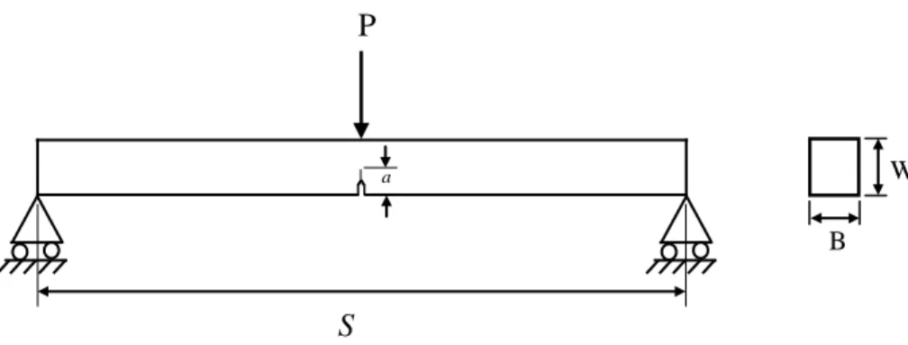
Fig. 2.3 (a) Shape and dimension of a single edge notched
specimen prepared for crack propagation test in high cycle fatigue (b) dimension of the notch.
21
Fig. 2.4 Microstructure in lateral and longitudinal direction (a and b) Hybrid MMC, (c and d) MMC with Al2O3 whiskers and
(e and f) Al alloy.
22
Fig. 2.5 Experimental setup. 24
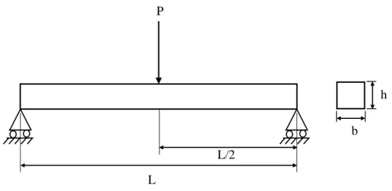
Fig. 2.6 Schematic illustration of three point bending test in smooth specimen.
24
Fig. 2.7 Schematic illustration of three point bending test in a single edge notched specimen.
27
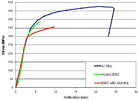
Fig. 3.1 Nominal bending stress versus deflection curves under monotonic loading.
30
Fig. 3.2 Number of cycles to crack initiation and final failure at different stress levels.
31
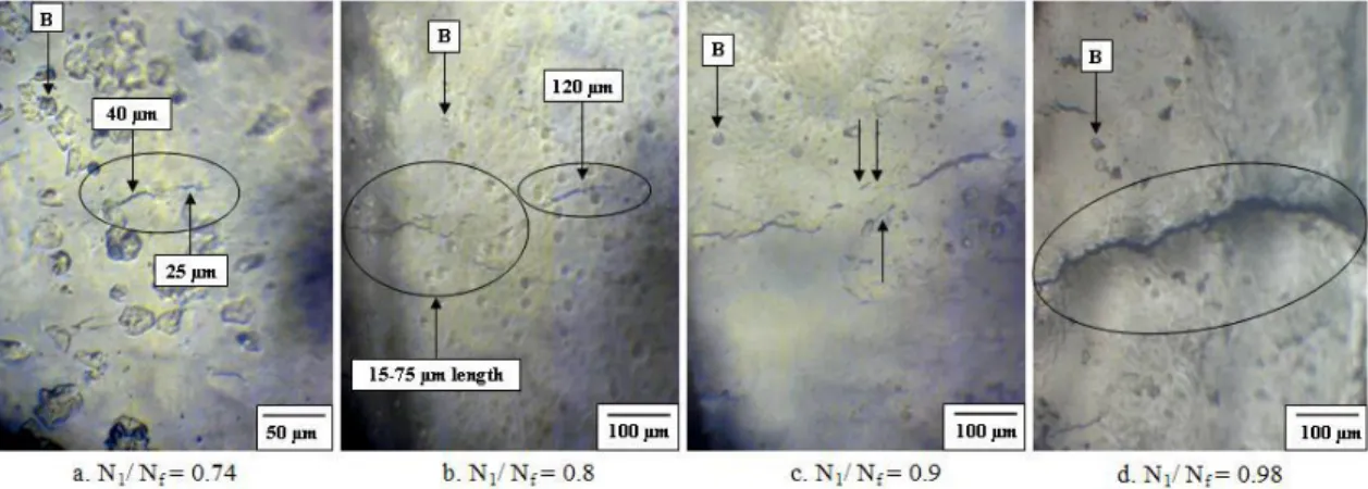
Fig.3.3 Initiation of microcracks at different stresses and cycle ratios.
31
Fig 3.4 Crack initiation and propagation at various stages of fatigue life of hybrid MMC: σc = 270 MPa, Nf = 8580
cycles.
Fig.3.5 Optical micrograph of crack initiation site at the matching tensile surface of the fractured specimen: hybrid MMC, 0.7 σc = 270 MPa.
33
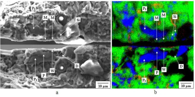
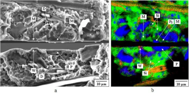
Fig. 3.6 Matching fracture surface of microcrack initiation site at the cluster of SiC particles (a) SEM micrograph (b) EDS mapping analysis: hybrid MMC, 0.7 σc = 270 MPa.
35
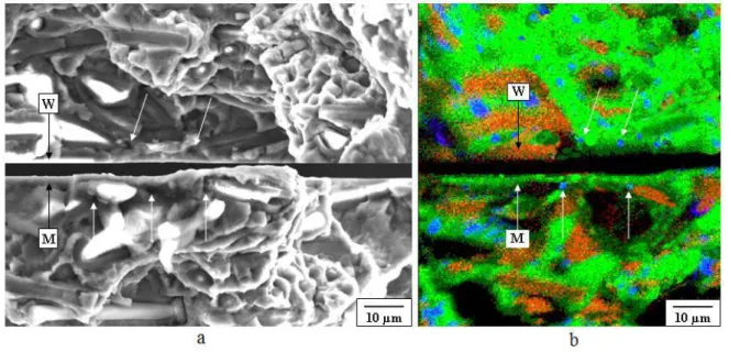
Fig. 3.7 Matching fracture surface of microcrack initiation site next to the edge of Al2O3 whisker (a) SEM micrograph (b) EDS
mapping analysis: hybrid MMC, 0.7 σc = 270 MPa.
35
Fig. 3.8 Matching fracture surface of secondary microcrack initiation and coalescence site (a) SEM micrograph (b) EDS mapping analysis: hybrid MMC, 0.7 σc = 270 MPa.
36
Fig.3.9 Crack initiation and propagation at various stages of fatigue life of MMC with Al2O3 whisker: σc = 250 MPa, Nf
= 6200 cycles.
41
Fig. 3.10 Optical micrograph of crack initiation site at the matching tensile surface of fractured specimen: MMC with Al2O3
whisker, 0.7 σc = 250 MPa.
41
Fig. 3.11 Matching fracture surface of microcrack initiation site (a) SEM micrograph (b) EDS mapping analysis: MMC with Al2O3 whisker, 0.7 σc = 250 MPa.
43
Fig. 3.12 Matching fracture surface of secondary microcrack initiation and coalescence site (a) SEM micrograph (b) EDS mapping analysis: MMC with Al2O3 whisker, 0.7 σc
= 250 MPa.
43
Fig. 3.13 Crack initiation and propagation at various stages of fatigue life of Al alloy : 0.7 σc = 332 MPa, Nf = 70000
cycles.
46
Fig. 3.14 Optical micrograph of crack initiation site at the tensile surface of both side of the fractured specimen.
Fig. 3.15 SEM micrograph of matching fracture surface: Al alloy, 0.7 σc = 332 MPa.
47
Fig. 3.16 Matching fracture surface of microcrack initiation site (a) SEM micrograph (b) EDS mapping analysis: Al alloy, 0.7 σc = 332 MPa.
48
Fig. 3.17 Matching fracture surface of secondary microcrack initiation and coalescence site (a) SEM micrograph (b) EDS mapping analysis: Al alloy: 0.7 σc = 332 MPa.
48
Fig. 3.18 Matching surface of striation (a) SEM micrograph (b) EDS mapping analysis: Al alloy, 0.7 σc = 332 MPa
49
Fig. 3.19 Schematic diagram of fatigue crack initiation and
propagation process at the fracture surface (a) Al alloy, (b) MMC with Al2O3 whisker and (c) Hybrid MMC
50
Fig. 3.20 Fatigue crack growth behaviour of hybrid MMC, MMC with Al2O3 whisker and Al alloy.
53
Fig.3.21 Fatigue crack growth in hybrid MMC: (a) Replica observation at the near threshold region, (b) Matching tensile surface at the near threshold region, (c) Replica observation at the stable crack growth region, (d)
Matching tensile surface at the stable crack growth region.
55
Fig. 3.22 Fatigue crack growth in hybrid MMC: (a) SEM
micrograph at the near threshold region, (b) EDS analysis at the near threshold region, (c) SEM micrograph at the stable crack growth region, (d) EDS analysis at the stable crack growth region
57
Fig. 3.23 Matching surface of striation formed in the stable crack growth region of hybrid MMC: (a) SEM micrograph, (b) EDS mapping analysis, (c) 3D analysis.
Fig. 3.24 3D analysis of crack propagation from one SiC particle to another in hybrid MMC: (a) Matching fracture surface at the near threshold region, (b) Crack surface profile at the near threshold region, (c) Matching fracture surface at the stable crack growth region, (d) Crack surface profile at the stable crack growth region.
61
Fig. 3.25 Fatigue crack growth in MMC with Al2O3 whisker: (a)
Replica observation at the near threshold region, (b) Matching tensile surface at the near threshold region, (c) Replica observation at the stable crack growth region, (d) Matching tensile surface at the stable crack growth region.
64
Fig. 3.26 Fatigue crack growth in MMC with Al2O3 whisker: (a)
SEM micrograph at the near threshold region, (b) EDS analysis at the near threshold region, (c) SEM micrograph at the stable crack growth region, (d) EDS analysis at the stable crack growth region.
66
Fig. 3.27 Matching surface of striation formed at the stable crack growth region of MMC with Al2O3 whisker (a) SEM
micrograph, (b) EDS mapping analysis.
67
Fig. 3.28 3D analysis of crack propagation from one Al2O3 whisker
to another in MMC with Al2O3 whisker: (a) Matching
fracture surface at the near threshold region, (b) Crack surface profile at the near threshold region, (c) Matching fracture surface at the stable crack growth region, (d) Crack surface profile at the stable crack growth region.
68
Fig. 3.29 Fatigue crack growth in Al alloy: (a) Replica observation at the near threshold region, (b) Matching tensile surface at the near threshold region, (c) Replica observation at the stable crack growth region, (d) Matching tensile surface at the stable crack growth region.
Fig. 3.30 Fatigue crack growth in Al alloy: (a) SEM micrograph at the near threshold region, (b) EDS analysis at the near threshold region, (c) SEM micrograph at the stable crack growth region, (d) EDS analysis at the stable crack growth region.
71
Fig. 3.31 3D analysis of crack propagation in Al alloy: (a) Matching fracture surface at the near threshold region, (b) Crack surface profile at the near threshold region, (c) Matching fracture surface at the stable crack growth region, (d) Crack surface profile at the stable crack growth region.
72
Fig. 3.32 Schematic diagram of fatigue crack growth mechanism at the near threshold region and stable crack growth region (a) (b) Hybrid MMC (c) (d) MMC with Al2O3 whisker and
(e) (f) Al alloy.
75
Fig. 4.1 Model-1 representing SiC particles reinforced clustering region with 58 vol% of reinforcement in hybrid MMC: (a) schematic illustration of the periodic particle and whisker arrangement (b) 1/8 of one unit cell, analysis based on symmetry (c) finite element mesh.
81
Fig. 4.2 Model-2 representing reinforcement clustering region (SiC particles and Al2O3 whisker) with 51 vol% of
reinforcement in hybrid MMC: (a) schematic illustration of the periodic particle and whisker arrangement (b) 1/8 of one unit cell, analysis based on symmetry (c) finite
element mesh.
Fig. 4.3 Model-3 representing reinforcement clustering region (SiC particles and Al2O3 whisker) with 30 vol% of
reinforcement in hybrid MMC: (a) schematic illustration of the periodic particle and whisker arrangement (b) 1/8 of one unit cell, analysis based on symmetry (c) finite
element mesh.
82
Fig. 4.4 Model-4 representing the non-clustering region of hybrid MMC where particle and whisker is placed in series: (a) schematic illustration of the periodic particle and whisker arrangement (b) 1/8 of one unit cell, analysis based on symmetry (c) finite element mesh.
83
Fig. 4.5 Model-5 representing the non-clustering region of hybrid MMC where particle and whisker is placed in parallel: (a) schematic illustration of the periodic particle and whisker arrangement (b) 1/8 of one unit cell, analysis based on symmetry (c) finite element mesh.
83
Fig. 4.6 Numerical results normal stress along loading direction (a) in the SiC particulate reinforcement clustering region model-1, (b) in the SiC particle and Al2O3 whisker
reinforcement clustering region model-2, (c) in the SiC particle and Al2O3 whisker reinforcement clustering region
model-3, (d) in the reinforcement non-clustering region model-4 and (e) in the reinforcement non-clustering region model-5.
86
Fig. 4.7 Shear stresses developed in the clustering region of hybrid MMC (a), (c) and (e) τxy in model-1, model-2 and model-3
respectively, (b), (d) and (f) τxz in model-1, model-2 and
model-3 respectively.
Fig. 4.8 Shear stresses developed in the non-clustering region of hybrid MMC (a), (c) τxy in model-4 and model-5
respectively, (b) and (d) τxz in model-4 and model-5
respectively.
88
Fig. 4.9 Comparison of (a) the maximum normal stress developed in the clustering and non-clustering regions, (b) the
maximum and minimum normal stresses developed on the particle–matrix and whisker–matrix interfaces in the clustering and non-clustering regions.
LIST OF TABLES
No.
Captions
Page
Table 2.1 Chemical compositions of AC4CH alloy (wt. %). 20 Table 2.2 Mechanical properties of reinforcement and tested
materials.
23
Table 3.1 Fracture stress σc of three materials under bending 30
Table 3.2 Fatigue crack growth test results (unit: ∆K (MPa m1/2),
da/dN (m/cycle), CTOD (m)). 53
Table 3.3 Number of secondary microcracks formed in front of the crack tip of three materials at the near threshold region (range of ∆K (unit: (MPa m1/2
): Hybrid MMC 6.6-6.75, MMC with Al2O3 5-5.2 and Al alloy 4.2-4.45) and stable
crack growth region (range of ∆K (unit: (MPa m1/2
): Hybrid MMC 12-12.6, MMC with Al2O3 10-10.7 and Al
alloy 10.5-11)
56
Table 3.4 Area fraction of striation in the stable crack growth region of three materials (∆K: Hybrid MMC- 16.4 MPa m1/2, MMC with Al2O3-13 MPa m1/2and Al alloy-18 MPa
m1/2)
59
Table 3.5 Area fraction of SiC particle and Al2O3 whisker fracture
and debonding between particle-matrix and whisker-matrix and area fraction of dimples of hybrid MMC in near threshold region (∆K: 6.6 MPa m1/2
) and stable crack growth region (∆K: 16.4 MPa m1/2
)
CHAPTER-1
INTRODUCTION
1.1 Background
In recent years, stringent requirements of materials quality in automotive and aerospace industries have necessitated the development of lightweight materials. In order to obtain more efficient product for structural applications, it is necessary to improve wear and fatigue behaviour, weight reduction, high thermal conductivity, low coefficient of thermal expansion of the materials. Therefore, metal matrix composites (MMCs) have been widely considered as the possible substitute which could comply with those characteristics.
The development of MMCs has set the stage for a new revolution in materials. A metal matrix composite (MMC) combines into a single material a metallic base with a distinct phase of reinforcing constituent, which is usually non-metallic and is commonly a ceramic. The reinforcements can be either particles or fibers or the combination of both. The MMC materials can be classified according to the type and contribution of reinforcement component on the metallic matrix as:
Particle reinforced MMCs.
Short fiber/whisker reinforced MMCs Continuous fiber/whisker reinforced MMCs. Monofilament reinforced MMCs.
These composites, which possess higher stiffness, strength-to-weight ratio and wear resistance when compared with unreinforced matrices, have been cited for eventual use in
many structural, tribological and environmental applications. Recently, MMCs have become attractive materials for structural applications such as aerospace, automotive industry and wear applications, especially in the frictional area of braking systems because of their great advantages and mechanical performance. The major advantages of MMCs compared to unreinforced material are as follows:
Greater strength Improved stiffness Reduced density (weight)
Improved high temperature properties Controlled thermal expansion coefficient Improved abrasion and wear resistance Improved damping capability
The above advantages made these MMC materials more and more attractive and alternative in the engineering applications. The reinforcement and the matrix system for the MMCs are mainly determined by the intended application of the composites. For example, high thermal conductivity with improved ductility is needed for the MMC materials used in the frictional area e.g. brake disc rotor. Therefore, ceramics and high toughness aluminium should be chosen as reinforcement and matrix respectively. Besides, the combined application of two or more reinforcement is possible by using hybrid techniques. A brake disc structure made by partially reinforced MMC is shown in Fig. 1.1. Despite their great advantages, the high production cost, poor ductility and low toughness of MMCs are the major barriers for their structural applications. For minimizing these limitations, a clear
understanding of the micro-mechanisms of damage characteristics of MMCs is necessary to design the microstructure of these materials. Many researchers have investigated the damage characteristics of MMCs during the past few decades [1-64]. According to their study, Fabrication process of the MMCs plays an important role to minimize the limitation (high cost, low toughness) in the structural applications. The MMC materials can be manufactured by many different techniques [1, 2]. The fabrication techniques basically divided into two categories:
(1) Solid state includes powder metallurgy and diffusion bonding and (2) Liquid state includes infiltration, dispersion and spraying.
MMCs of commercial applications are now produced by the liquid state process because of the following advantages over the solid state process:
Less expensive.
Liquid metal is easier to handle than are powders. Complex shape can be produced by liquid state process.
Among the various types of the liquid state fabrication techniques, squeeze casting have now become one of the most feasible techniques for the production of low cost MMCs and complex shape components [2]. The emergence of squeeze casting as a production process has given materials and process engineers a new alternative to traditional approaches of casting and forging [3, 4]. Squeeze casting is the process designating solidification of liquid metal under pressure. Pressure during solidification helps to achieve zero defects with improved metallurgical properties. Additionally, compared to another casting method e.g. gravity or die casting, a wide range of alloy can be cast using squeeze casting. Preparation
of the whisker/particle perform is an important step in the fabrication of MMCs by squeeze casting method. Reinforcement breakage, porosity, inhomogeneous reinforcement orientation and bad interfacial bonding in the composites are the barriers to obtain adequate strength and mechanical properties of MMCs.
1.2 Application of MMCs
In the past 15-20 years, MMCs have emerged as a class of materials capable of advanced structural, aerospace, automotive and wear applications. These materials provide the specific mechanical properties necessary for elevated and ambient temperature applications. Up to now, the major applications served by the MMCs in the automotive industries include selectively reinforced pistons for diesel engines, selectively reinforced cylinder bores in Al engine blocks, intake and exhaust valves, drive-shafts and prop-shafts, brake components (discs, rotors and calipers) and power module components for hybrid and electric cars [5]. Reduction of overall vehicle weight is important for improving fuel economy. Therefore, the application of MMCs for disc brake rotor has been receiving considerable world wide attention. It has been found that, approximately 52% weight saving is possible for a brake rotor if it is substituted by MMC than the cast iron [6]. Moreover, owing to the high thermal conductivity, SiC particles reinforced aluminium composites provides additional advantages for the thermal management of the brake system. Metal matrix composites are finding a wide range of applications in aerospace industries. Aeronautical MMC applications have been established in the structural, aero-propulsion and subsystem categories. Aero-structural components include ventral fins, fuel access door covers and rotor blade sleeves. Moreover, few MMC applications have been established in the space systems [5]. The MMC materials are also used in the industrial, recreational and infrastructure applications. Industrial applications include cemented carbide and cermet materials, electroplated and impregnated diamond tools, Cu and Ag MMCs for electrical contacts, erosion resistance cladding for the petrochemical industry, Cu-infiltrated steel components, and TiC-reinforced Fe and Ni alloys. The TiC-reinforced
Fe and Ni based MMCs are used in the wide range of industrial operations such as cutting, rolling, pelletizing, stamping, piercing, warm metalworking, drawing, forming and punching. Components include hammers, impact dies, canning tools, crimp rollers, check valves, extruder nipples, bending dies, extrusion dies and hot forging die inserts [7]. Moreover, MMC components used in the recreational purpose include golf club shafts and heads, skating shoes, base ball shafts and bicycle frames. Infrastructure applications include Al/B4C MMCs for nuclear waste containment and continuously reinforced Al/Saffil MMCs
for overhead power transmission conductors. MMCs are also in use as microprocessor lids and integrated heat sinks in electronic packaging [5].
1.3 Literature review
Although MMCs have many advantages, problems related to their poor damage tolerance under monotonic or cyclic loads remain [8]. Many applications for MMC materials involve cyclic loading, making the fatigue properties of these materials of critical interest. When a component is subjected to relatively high cyclic loads, high densities of microcracks form simultaneously. From one crack, a larger crack grows that eventually propagates and causes failure. Elucidating the mechanisms of the initiation and growth of this main crack are essential to understanding and predicting the fatigue life of a material. Despite this fact, the exact role of the reinforcement phase in fatigue crack initiation and growth processes as well as their influence in fracture mechanism is not well understood. Although it has been shown that reinforcement can increase the fatigue life of mono-reinforced composite materials, this effect is reportedly dependent on the strengths of the
matrix and the reinforcement/matrix interfaces [9-12]. Based on this fact, the literature review has been carried out as follows.
1.3.1 Fatigue damage and crack initiation in MMC
Fatigue failure of metallic materials is induced by the nucleation of one or several microcracks which propagate slowly during cyclic loading until one of them reaches the critical size and catastrophic failure occurs. In moderate lifetime regime, fatigue life is dominated by the crack initiation stage, while the life is dominated by crack propagation stage at high applied strain amplitude in a very short lifetime regime [13]. The total fatigue life of the material is determined by the combination of the crack initiation life and the crack propagation life. In addition the fatigue limit of smooth specimens is often determined by the ability of nucleating a crack from microstructural inhomogenities and surface defects [14]. Numerous studies have been performed to observe the progressive development of damage during cyclic deformation in MMCs. These studies investigated that damage was initially generated randomly throughout the specimens, and the dominant damage micro-mechanisms detected at this stage were reinforcement fracture [15-18], decohesion at the matrix/reinforcement interface [8, 18], and the formation of the matrix cracks [8]. This situation of homogeneous damage continued until a dominant microcrack was nucleated at the specimen surface, and damage was then rapidly localized around the propagating crack. The broken reinforcements were usually fractured by cracks perpendicular to the loading axis. This failure mechanism is normal to particulate reinforced MMCs tested in tension [19] and this indicated that the ceramic particles were fractured during the tensile part of the fatigue cycle. As in the specimens tested in tension,
the fracture probability increased with reinforcement size. In addition, elongated reinforcements oriented in the loaded direction were more prone to fail than equiaxed ones. All studies reported that particle clusters, where the local volume fraction of reinforcements is very high, were preferential sites for damage nucleation [17, 18]. Ceramic particles broken by cracks parallel to the loading axis were also found in two Al-matrix composites reinforced with alumina particles [15]. Their fracture morphology was similar to that found in MMC tested in compression [20], and is representative of particles broken by splitting during the compressive part of the fatigue cycle. Damage by interface decohesion and matrix cracking was also observed throughout the specimen in other MMC composites. They were mainly concentrated at or near the ends of the elongated reinforcements and whiskers [8, 18] but no influence were found of the reinforcement size in the failure probability. In addition, decohesion was often observed in particle clusters and this was partially attributed to the difficulties to infiltrate the matrix in this regions, which led to poor interfacial bonding. Moreover, few researchers have also explained the progression of damage during cyclic deformation [17, 18, 21]. These simulations demonstrate that the stresses transferred from the matrix to the particles increased during cyclic loading as a result of the cyclic hardening of the matrix. The stresses acting on the reinforcements and on the interface increased progressively during cyclic loading thus increasing the number of damaged particles.
1.3.2 Preferential sites for crack initiation in MMC
The microstructural features which led to the initiation of a fatigue crack were determined from analysis of the fracture surfaces as well as of longitudinal sections under
the scanning electron microscope (SEM). These studies provided different results depending on the stress level during fatigue. A large numbers of microcracks were rapidly initiated at the specimen surface from broken or decohered particles when the fatigue stress amplitude was similar to the composite yield strength [22, 23]. These microcracks grow quickly and coalesce to form a dominant crack, which leads to specimen failure. Thus, the stiff ceramic reinforcements act as preferential sites for crack nucleation, and are ultimately responsible for the poor low cycle fatigue properties of MMCs. Many researchers have observed that in cast composites, cracks were initiated by debonding at the interface in materials reinforced with particles, whiskers and short fibers. Chawla et al. [24] found microcracks 10 µm in length early in the fatigue life at the particle/matrix interface while studying 2080 Al/SiCp composite. This study also found that the number of cycles
necessary to initiate a crack was significantly lower in the composites than in the unreinforced alloy, even if the inclusion size was similar in both materials. Moreover, Levin and Karlsson [25] reported that cracks in a 6061/15 vol% SiC p composite initiated near the particle/matrix interface, in regions of high volume fraction of reinforcement, or by fracturing of individual particles, which were stressed more highly than particles completely within the matrix. This study indicates that fatigue crack initiation and failure may be more likely to take place at defects at the surface of the specimen. Chen and Tokaji [26] observed that the addition of SiC particles in Al alloy matrix makes the crack initiation easier and the fatigue crack initiates at the particle/matrix interface. Bonnen et al. [11] explained the fatigue behaviour of 2xxx series aluminium alloy reinforced with 15 vol% SiCp. They observed that fatigue cracks occasionally originated at large SiC particles or
whisker-reinforced MMCs. In case of whisker-reinforced composites, debonding was always localized at the end of the whiskers and fibers where the interfacial stresses were greatest [27]. This crack initiation mechanism in composites was attributed to the formation of weak interfaces due to either lack of complete infiltration or to excessive contact between the molten matrix and the ceramic whiskers. Chen et al.[25] have investigated the crack initiation mechanism in SiC whisker-reinforced Al matrix composite. They observed that in the low cycle regime, cracks originated early in fatigue life at the whisker-matrix interface. Williams [27] studied a cast SiCw/2124-T6 A1 composite in which cracks initiated at approximately 70 to 80% of the total lifetime at reinforcement/matrix interfaces. Besides, Ochi et al. [28] found that the crack initiation sites in both aluminium and magnesium alloy based MMCs were large size short fibers and clusters of short fibers.
1.3.3 Fatigue crack growth (FCG) in MMC
The effects of reinforcement characteristics (composition, morphology, size and volume fraction), processing parameters, and matrix heat treatment on fatigue crack growth (FCG) mechanism of MMCs have been extensively reviewed [1, 10, 29, 30]. A large number of systematic experimental studies have been conducted to determine the FCG responses of a variety of aluminium alloys reinforced with either SiC or Al2O3 particulates
[31-37]. These studies concluded that, in general, composite materials had higher threshold values in the stress intensity factor range, ∆Kth as compared to their monolithic materials.
The crack growth rate in the near threshold regime was very sensitive to the microstructure. The crack driving force in this regime was very small and crack propagation followed the weakest path in the material as the crack circumvents of the obstacles. Shang and Ritchie
[38] also explained this behaviour that at low applied stress intensity factor range ∆K where particle fracture is less likely, coarser SiC particles improved nominal fatigue thresholds (∆Kth) of MMCs due to enhanced roughness-induced crack closure. Moreover, Chawla et al.
[24] have observed that increasing volume fraction and decreasing particle size resulted in an increase in ∆Kth. They described the mechanisms responsible for this behaviour in terms
of load transfer from the matrix to the high stiffness reinforcement, increasing obstacles for dislocation motion and the decrease in strain localization with decreasing inter-particle spacing as a result of reduced particle size. Besides, the analysis of the micro-mechanisms of crack propagation in the near threshold region in MMC showed that the stress field around the crack tip was not intense enough to fracture the ceramic reinforcements [29, 38, 39] Botstein et al. [40] measured higher crack growth rates in the mid-growth rate (Paris Law) regime compared to the monolithic alloy while doing experiment with Al 2014-40% SiCp and Al 7091-30% SiCp composites. Sugimura and Suresh [33] also explained that large SiC particulate reinforced composite demonstrated lower FCG performance with increased ∆K because of a particle fracture dominated growth mechanism. In addition, several researchers have investigated the effect of particle clustering on FCG in Al-MMC [40, 41]. They determined that particle clustering significantly increased crack growth in the mid-growth rate (Paris Law) regime. Moreover, the effect of load ratio on FCG behavior of MMCs has also been investigated [34, 42]. In general, an increase in load ratio (positive R-ratio) resulted in a decrease in threshold stress intensity. Crack closure was generally considered to be the primary reason for the effect of load ratio on fatigue threshold. It has been widely demonstrated that the FCG response of a SiC particulate reinforced composites strongly depended on the nature of the underlying interaction
between the reinforcing particles and the advancing fatigue crack front. Several studies have explained this interaction in the form of particle matrix interfacial debonding [32, 35], particle fracture [33, 43], crack deflection around the reinforcing particles and subsequently FCG through the matrix [31, 43, 44] and particle crack trapping [45]. Besides, a few researches have pointed out the effect of whisker reinforcement on FCG. The orientation of whisker plays a vital role in advancing fatigue crack. Mason and Ritchie [39] observed higher threshold value in whisker reinforced composites compared to particulate reinforced materials when measured along the rolling direction. They attributed the effect to crack tip shielding by whisker pull-out and roughness induced closure. It has also been reported that when whiskers were aligned in the loading direction, the crack opening displacement reduced. The fatigue cracks were attracted to the whisker ends-which act as stress concentrators- inducing crack deflection [39, 46]. However, when the crack propagated parallel to the whisker, crack growth resistance of whisker-reinforced composites in the near threshold region was highly anisotropic [46].
1.3.4 Deformation and fracture of MMC
Many researchers have investigated the monotonic and cyclic fracture behavior and the fracture mechanisms of ceramic particulates/aluminium based MMCs. Large difference in strain carrying capability of elastically deforming reinforcement and plastically deforming matrix alloy determines the key mechanism of fracture of MMCs [48-55]. Thus, stress is concentrated near the interface edge between reinforcement and matrix or concentrated in the reinforcement, which causes interfacial debonding or reinforcement fracture. This reinforcement fracture or interfacial debonding may decrease the ductility of MMCs [48].
Plastic constraint developed in the matrix has strong effect on cyclic and monotonic deformation of MMCs. Deformation and failure of MMCs by the nucleation and growth of voids and within the ductile matrix were studied by Lorca et al. [54-56]. They demonstrated that due to constrained plastic flow of the matrix between the reinforcement particles in the MMCs, hydrostatic stresses develop in the matrix which plays an important role in the failure mechanism during monotonic and cyclic deformations [15, 54]. This hydrostatic stress enhances the nucleation of the voids in the matrix alloy. Different constraint levels on the matrix flow may control the local failure process (e.g. particle fracture, interfacial debonding and dimple fracture of matrix alloy). In the particulate composites, the plastic strain and voids around the inclusions spread throughout the matrix, whereas, in the whisker reinforced composite they are localized in the vicinity of the reinforcement [54]. The failure mechanism is greatly influenced by different loading conditions (e.g. monotonic and cyclic load). Poza et al. demonstrated the difference of fracture mechanism of a metal matrix composite under monotonic and cyclic loading condition [15]. The tension loaded reinforcements in the matrix are subjected to higher tensile stress than those loaded in fatigue results in high degree of reinforcement fracture. During the loading and unloading process in the cyclic deformation, cyclic hardening occurs due to the accumulation of plastic strain. During the monotonic deformation the plastic strain also develop, especially at the interface between reinforcement and matrix, but significantly lower than in cyclic deformation [15].
1.3.5 Research on hybrid MMC
A few investigations have been made recently [57-62] in which the influence of hybrid reinforcements such as silicon carbide + graphite, Al2O3 + silicon carbide and carbon fiber
+ alumina on the wear and tribological behavior was investigated.Moreover, some studies have focused on the fatigue crack growth behaviour and the fracture mechanism of hybrid MMC. For example, Song et al. [57] have investigated the wear behavior of Al/Al2O3/C
hybrid metal matrix composites. They observed that the wear resistance was remarkably increased compare with Al/Al2O3 composite due to hybrid effect. Other literature shows
that wear resistance of hybrid MMCs are higher under dry sliding condition but lower under lubricated sliding condition compared with the non-hybrid MMCs [58]. An analytical analysis considering tensile strength and stiffness enhancement in particle/fiber reinforced aluminium hybrid metal matrix composites was investigated by Jung et al. [59]. They have demonstrated that the strength and stiffness of hybrid composites were much larger than the fiber composite due to the cluster structure which increased the bending rigidity and change the fracture mechanism. Mason and Ritchie [39] have investigated the effects of whiskers and particles on fatigue crack growth in SiCp and SiCw hybrid composites. They observed
that crack growth resistance in the composites was superior to that in a monolithic alloy at low stress intensity ranges, ∆K, owing to the formation of tortuous crack paths, which in turn enhanced roughness-induced crack closure. Oh and Han [47] pointed out that the increase in ∆Kth with increasing particle content in hybrid MMCs reinforced with Al2O3
short fibers and Al2O3 particles indicated that the crack growth resistance was enhanced
over the entire ∆K, and thus hybrid-reinforced composites provided better control of damage tolerance properties over conventional particle-reinforced composites. Moreover,
the fracture mechanisms in cast hybrid MMC under monotonic and cyclic loads were investigated by Rafiquzzaman et al. [63, 64]. They observed that the fracture of hybrid MMC was dominated by the debonding of the particle–matrix and whisker–matrix interfaces followed by void nucleation and coalescence in the Al alloy matrix. This interfacial debonding was due to the cyclic hardening caused by the accumulation of plastic strain at the interface between the matrix and the reinforcement.
The above results concerning microcrack initiation and propagation mechanism as well as damage and failure criteria weigh in favor of either particulate or whisker reinforced MMCs. At present, studies of cast hybrid MMCs are limited in the investigation of fracture mechanism and wear behaviour. Moreover, the studies of the effect of hybridization on fatigue crack initiation and propagation mechanisms are rare. As hybrid MMC materials have the interfaces between the particle/matrix and whisker/matrix, the resulting strength of the interfaces for microcrack initiation and propagation mechanism will undoubtedly play an important role in many structural applications. The crack initiation location and the crack initiation mechanism as well as their stage by stage growth to final failure give critical information for the design or placement of the mechanical component made by MMC materials. Therefore, it is believed by the authors that a through understanding of the low and high cycle fatigue behaviour of cast hybrid reinforcement composites would contribute significantly to the use of these materials in large scale structural applications, e.g., the brake disc of a high speed railway coach. Therefore, it is necessary to understand the initiation and early propagation mechanisms of fatigue microcracks in cast hybrid MMCs during low cycle fatigue as well as the behaviour of the fatigue crack growth during high cycle fatigue owing to evaluate the overall fracture mechanism and the fatigue life. In
the present study, the initiation, interaction, and coalescence of fatigue microcracks in smooth specimens of cast hybrid MMC reinforced with SiC particles and Al2O3 whiskers
were investigated. In addition, the crack growth behaviour in a notched specimen of hybrid MMC during high cycle fatigue was also investigated. To compare the results of crack initiation and propagation mechanisms in low and high cycle fatigue, another two types of materials were used, cast MMC reinforced with Al2O3 whiskers, and unreinforced cast Al
alloy. The effect of hybrid reinforcement on the fatigue crack initiation and early propagation mechanisms in low cycle as well as the crack growth behaviour in high cycle fatigue is discussed through the comparison of the observed mechanisms in the three materials.
1.4 Scope and objectives
The aim of this research is to investigate the microcrack initiation and propagation mechanisms in Al based cast hybrid metal matrix composites reinforced with SiC particles and Al2O3 whiskers. The specific objectives of the present research are as follows:
To investigate the role of reinforcement on fatigue crack initiation.
To investigate the effect of cyclic load on crack initiation and early propagation mechanism of MMC.
To investigate the hybridization effect on fatigue crack initiation and propagation mechanism.
To investigate the fatigue crack growth behaviour in the near-threshold region and stable-crack growth regions.
To evaluate the fracture mechanism of hybrid MMC in low cycle and high cycle fatigue.
1.5. Outline of the thesis
The thesis has been organized into five chapters. The contents of each chapter are summarized below:
Chapter 1 presents an introduction of the research, which describes the background, the
motivation, an extensive literature review, the objectives and the scope of this research. In Chapter 2, materials fabrication and its microstructure, the experimental set up and the experimental procedures were thoroughly discussed.
In Chapter 3, results and discussion of the experimental results are presented. The results of the initiation of microcracks, their growth and final failure during low cycle fatigue were enumerated in this chapter. In addition, the results of the fatigue crack growth mechanism during high cycle fatigue were discussed.
Chapter 4 presents the results of the numerical analysis conducted in this research. Three
dimensional unit cell models were developed using finite element method (FEM) to characterize the crack initiation and propagation mechanism and the interface strength of hybrid MMC.
Chapter 5 presents the general conclusions and directions of the future investigation of this
CHAPTER- 2
MATERIALS AND EXPERIMENTAL PROCEDURES
2.1 Introduction
This chapter describes the details of the fabrication method of the materials used in the test. The specimen preparation for the monotonic and fatigue test as well as for the investigation of the microcrack initiation and propagation mechanism in low cycle and high cycle fatigue is explained in this chapter. For minimizing the limitation of MMCs, cast hybrid MMC reinforced with SiC particles and Al2O3 whiskers was introduced in this
research for structural applications especially in the application of a brake disc of a high speed rail way coach. Other two materials cast MMC with Al2O3 whisker and cast Al alloy
were also tested. Finally the microcrack initiation and propagation phenomena and fracture mechanism of cast hybrid MMC in low cycle and high cycle fatigue were explained through the comparison of the observed mechanism of other two materials. The MMC materials were fabricated successfully by the squeeze casting method. Monotonic and cyclic fatigue tests were conducted by MTS servopulser machine with a special bending fixture. The fracture surfaces of the specimens were thoroughly examined by the SEM and EDS. The three-dimensional (3-D) analysis was also carried out to examine the roughness of the fractured surfaces by Alicona Mex software.
2.2 Materials Fabrication
Metal Matrix composites generally produced either by liquid metallurgy (Stir casting and liquid metal infiltration) or powder metallurgy techniques [1, 2, 5]. In the liquid metallurgy, the reinforcement particulates are incorporated into a molten metallic matrix,
Fig.2.1 Squeeze casting method
followed by mixing and casting of the resulting MMC [65]. For the production of low cost and complex shaped MMCs, squeeze casting technology have now become the most feasible techniques. In the squeeze casting process, liquid metal is injected into the interstices of particles and whiskers usually called as a preform. Preforms are made up of reinforcement particles and whiskers with a known volume fraction of particles and whiskers and it is designed with specific shapes to form an integral part of finished products in the as-cast form [66]. Very high pressure is applied to develop the effective bonding between the liquid metal and the reinforcement particles and whiskers. Since, pressure is applied throughout the process, molten metal flows into the shrinkage cavities and the gasses like hydrogen gets dissolved and remains there in the solution. Thereby, defects like porosity and shrinkage is eliminated [67]. The schematic diagram of squeeze casting method is shown in Fig. 2.1.
Press table Pusher Form Base plate Preform Melting Al Pressure direction
In the present study, three types of materials were used: cast aluminum alloy JIS-AC4CH [68], cast MMC with 9 vol% Al2O3 whiskers as reinforcement, and cast hybrid
MMC. The hybrid MMC was fabricated with 21 vol% SiC particles and 9 vol% Al2O3
whiskers as reinforcements and the aluminum alloy JIS-AC4CH as matrix. The three types of materials were fabricated using the squeeze casting process with a 100 MPa maximum pressure, using a hybrid preform made of SiC particles and Al2O3 whiskers for the hybrid
MMC and a preform of Al2O3 whiskers for MMC with Al2O3. The squeeze casting pressure
of 100 MPa was applied to overcome the resistance against flow and to press the melt into all the open pores of the hybrid preform. The materials were heat treated using the T7 process. The chemical composition of AC4CH alloy is listed in Table 2.1.
Table 2.1 Chemical composition of AC4CH alloy, (wt%)
Si Fe Mg Ti Al
7.99 0.2 (max.) 0.57 0.07 Bal.
2.3 Specimen Preparation
To investigate the hybrid effect in the microcrack initiation mechanism and stage by stage growth till to final failure in low cycle fatigue, rectangular bar smooth specimens were prepared for all three materials. The specimen dimensions were as follows: length of 100 mm, thickness of 6 mm and width of 8 mm. The shape and dimension of the specimen are shown in Fig 2.2. Moreover, for the crack propagation test in the high cycle fatigue, rectangular bar single edge notched specimens were prepared as shown in Fig 2.3. The specimen dimensions for the high cycle fatigue were as follows: length of 100 mm,
thickness of 8 mm width of 6 mm and a notch width of 0.5 mm. All the specimens were cut out from a disc. The machined surfaces of the specimens were polished using a polishing machine with 15, 3, and 1 µm diamond particles sequentially until all scratches and surface machining marks were removed. Due to the formation process of the preform the whiskers in the both MMCs are randomly oriented in a plane. In this study, 'Longitudinal cross section' is defined as the plane and 'lateral cross section' is defined as the one perpendicular to the plane.
8
6 100
6
Fig. 2.2 Shape and dimension of the rectangular bar smooth specimen prepared for microcrack initiation test in low cycle fatigue.
(a)
(b)
Fig. 2.3 (a) Shape and dimension of a single edge notched specimen prepared for crack propagation test in high cycle fatigue (b) dimension of the notch.
Fig. 2.4. Microstructure in lateral and longitudinal direction (a and b) Hybrid MMC, (c and d) MMC with Al2O3 whiskers and (e and f) Al alloy.
2.4 Microstructural features
The microstructures of the three materials in the lateral and the longitudinal cross sections are shown in Fig. 2.4. Most of the SiC particles in the hybrid MMC were rectangular with sharp corners (Fig. 2.4a, b), and most of the Al2O3 whiskers in both MMC
materials were roller-shaped (Fig. 2.4 a,b and c,d). The SiC particles had an average length of 23 µm. The average diameter of the Al2O3 whiskers was 2 µm in both MMCs. The
average length of the Al2O3 whiskers in hybrid MMC was 35 µm and in MMC with Al2O3
whiskers 38 µm. The Al2O3 whiskers were randomly oriented in the same plane as the
longitudinal direction of the specimen. In the Al alloy, the average grain size was found to be 48 µm. The Si particles in the Al alloy were round with an average diameter of 3 µm. At frequent intervals, clusters of SiC particles and Al2O3 whiskers were observed in both of
the MMC materials, as indicated by the broken lines in Fig. 2.4 b and d, respectively. Clustering of Si was also observed in the Al alloy, as shown by the broken line in Fig. 2.4f. The mechanical properties of reinforcement and tested materials are shown in Table 2.2. The listed properties for both MMCs are along the longitudinal direction.
Table 2.2. Mechanical properties of reinforcement and tested materials
Parameters Al2O3 SiC Al alloy AC4CH Hybrid MMC MMC with Al2O3
whisker Young‟s modulus (GPa) 380 450 70.0 142 104 Poisson‟s ratio 0.27 0.20 0.33 0.28 0.29
Yield strength (MPa) - - 131 166 141
Tensile strength (MPa) - - 262 228 200
Fig. 2.5 Experimental setup
Fig. 2.6 Schematic illustration of three point bending test in smooth specimen P
L
L/2
b h
2.5 Experimental set up and Procedure
2.5.1 Microcrack initiation test in low cycle fatigue
For microcrack initiation study in low cycle fatigue, conventional three point bending tests were carried out on a rectangular bar smooth specimens to reduce the observation area in the maximum stress location. The three point bending tests were performed using special bending fixtures equipped with a 5 kN load cell in a Shimazu ServoPulser. The span distance was 60 mm. Load and deflection data were recorded by a computer data acquisition system. The experimental set up is shown in Fig. 2.5. First the monotonic bending tests were conducted at a displacement rate of 0.0025 mm∙s-1. The strength of the three different materials was calculated from the maximum load at failure as a nominal bend stress σc. Schematic illustration of three point bending test in smooth specimen is
shown in Fig 2.6. The nominal bending stress was calculated from the following equation,
2 3 bh PL ……….…(2.1)
Where, P is the applied load. The specimen dimension L, b and h are defined in figure 2.6. Thereafter, cyclic fatigue tests were conducted in the load control mode under the load ratio
R = 0.1 at the frequency of 0.5 Hz. Three tests for each material were conducted with the
maximum stress of 0.7 σc, 0.8 σc, and 0.9 σc. All tests were carried out at room temperature.
The number of cycles to failure was taken as the fatigue life (Nf). For one stress amplitude,
one specimen was used; therefore error bars in the number of cycles were not employed. The plastic replica technique was used to study the initiation and early propagation of microcracks at various times during the fatigue life. During replication, the specimen was held at mean load to ensure that any cracks that might be present would be fully opened.
Replicas were taken using Bioden replicating films softened in acetone. Finally, the replicas were examined using an optical microscope. The tensile surface of the broken specimens was also examined with an optical microscope to determine the crack initiation location. Fracture surfaces were comprehensively examined in a scanning electron microscopy (SEM) to determine the microcrack initiation mechanism and microscopic fracture mode as well as microscopic mechanism governing fracture. Energy-dispersive x-ray spectroscopy (EDS) analysis was used to identify the constituents on the fracture surfaces. Special effort was made to take the matching photographs from the two halves of the broken specimens to assess the relative incidence of particle/whisker cracking and particle/matrix or whisker/matrix interfacial debonding. Prior to testing, no cracks were seen but the shape of large Al2O3 whiskers could be identified in the microscopy images. In
this study, "crack initiation" is defined as the point at which a black line of several micrometers is first observed in the magnified replica image, during the cyclic loading test.
2.5.2 Crack propagation test in high cycle fatigue:
Experiments of the fatigue crack growth in high cycle fatigue were carried out on rectangular bar single edge notched specimen. A conventional three point bending tests were performed using special bending fixtures equipped with a 5 kN load cell in a Shimazu ServoPulser as similar to the microcrack initiation test previously described. A schematic illustration of the three point bending test in a single edge notched specimen is shown in Fig. 2.7. The span distance was 60 mm. Load and deflection data were recorded by a computer data acquisition system. Tests were conducted under ∆K control mode with a constant stress ratio R = 0.1 in sinusoidal loading in accordance with the guidelines in
Fig. 2.7 Schematic illustration of three point bending test in a single edge notched specimen.
ASTM E647. The instantaneous stress intensity during the experiment was measured by using the following equation:
) / ( 1 f a W W B P K ………(2.2)
Where, P is the applied load, a is the crack length and f(a/W) is a dimensionless geometry function. The specimen dimensions B and W are defined in Fig. 2.7. The geometry function was calculated by using the following equation:
2 2 3 1.99 1 2.15 3.93 2.7 1 2 1 2 3 ) / ( W a W a W a W a W a W a W a W S W a f .(2.3)
Where, S is the span distance. A decreasing ∆K procedure was used to determine the threshold stress intensity. The stress intensity corresponding to a crack growth rate of 10-11 m/cycle was taken as the threshold stress intensity, ∆Kth. Once the threshold stress intensity
was determined, the crack growth was continued by increasing ∆K. Crack growth was B
W
S
P
measured using a Bioden replicating films softened in acetone. The replicas were examined using an optical microscope. The tensile and fracture surfaces were comprehensively examined using scanning electron microscopy (SEM) and energy-dispersive x-ray spectroscopy (EDS) to characterize the near threshold region and stable or mid-growth rate region. Moreover, the three-dimensional (3-D) analysis was carried out to examine the roughness of the fracture surface using the Alicona Mex software [69]. Additionally, the areas of dimples, interfacial debonding of particle/matrix and whisker/matrix, particle and whisker fracture were also examined. To determine the area fraction of the particle/whisker fracture and interfacial debonding in the near threshold region and stable crack growth region, a particular area of 300 x 300 µm2 is selected in both the regions. Therefore, the fraction of the particle and whisker fracture area is defined as the total particle and whisker fracture area divided by the total area measured. The area fraction of particle/matrix and whisker/matrix debonding in both the regions as well as the area fraction of striation formed in the stable crack growth region are also measured by the same procedure.
CHAPTER-3
EXPERIMENTAL RESULTS
3.1 Introduction
This chapter describes the experimental results of this research. The specimens are monotonically and cyclically deformed to failure at room temperature under conventional three-point bending test. The initiation of the microcracks and their stage-by-stage propagation till to final failure during low cycle fatigue and crack growth behaviour during high cycle fatigue are described by using the plastic replica observation. Moreover, SEM observations of the fracture surfaces are made to describe the fracture mechanism of the materials and EDS mapping analysis is used to identify the constituents on the fracture surfaces. The measured areas of dimples, interfacial debonding and particle/whisker fractures on the fracture surfaces are also examined. In addition, the roughness of the fracture surfaces is examined by the three-dimensional (3-D) analysis and the results are presented in this chapter. The mechanism of fatigue crack initiation and propagation during low and high cycle fatigue is thoroughly discussed in this chapter.
3.2 Monotonic test
In order to obtain the strength of the materials, monotonic bending tests were conducted. The strength of the three different materials was calculated from the maximum load at failure as a nominal bend stress σc. The nominal bending stress and deflection
Fig. 3.1 Nominal bending stress versus deflection curves under monotonic loading.
Table 3.1 Fracture stress σc of three materials under bending
Fig.3.1. The specimens composed of hybrid MMC and MMC with Al2O3 whiskers
fractured at 386 and 357 MPa, respectively; the Al alloy, rather than fracturing, plastically collapsed at 475 MPa. The fatigue test was conducted based on the fracture stress of these three materials. The collapse stress of the Al alloy was used as the fracture stress during fatigue testing. The fracture stress σc of the three materials is listed in Table 3.1.
Materials Fracture stress σc (MPa)
Hybrid MMC 386
MMC with Al2O3 357
Fig. 3.2 Number of cycles to crack initiation and final failure at different stress levels.
3.3 Low cycle fatigue test
In order to obtain the crack initiation and propagation mechanism as well as the fatigue life, fatigue tests were conducted in the load control mode. Fig. 3.2 shows the number of cycles needed to initiate microcracks, Ni, and final failure, Nf, at different stress levels of
the specimens composed of hybrid MMC, MMC with Al2O3 whiskers, and unreinforced Al
alloy. Moreover, Fig. 3.3 displays the microcrack initiation at different cycle ratios, Ni/Nf,
of these materials. The crack initiation life and the total fatigue life of the hybrid MMC were found to be superior to those of the MMC with Al2O3 whiskers in low cycle fatigue, as
shown in Fig. 3.2. In the hybrid MMC, microcracks were initiated very early in the fatigue life. For example, at the 0.7 σc stress level, microcracks were initiated only at 1400 cycles
(Fig. 3.2), which is 16% (Fig. 3.3) of the fatigue life. At the same stress level, microcracks were initiated at 1200 cycles (Fig. 3.2), which is 19% (Fig. 3.3) of the fatigue life of the MMC with Al2O3 whiskers, and at 52,000 cycles (Fig. 3.2), which is 74% (Fig. 3.3) of the
fatigue life of the unreinforced Al alloy. Similar phenomena of micro-crack initiation were also observed under 0.8 σc and 0.9 σc.This clearly demonstrates that the propagation life in
the cycle ratio for the hybrid MMC was large compared to that of the other two materials.
3.4 Microcrack initiation and propagation in low cycle fatigue 3.4.1 Hybrid MMC
The evolution of fatigue microcracks on the surface of the materials can be observed from optical micrographs of the same areas on replicas. The optical micrographs of replicas obtained at various stages of fatigue testing of the hybrid MMC specimen at 0.7 σc = 270
Fig. 3.4 Crack initiation and propagation at various stages of fatigue life of hybrid MMC: σc = 270 MPa, Nf = 8580 cycles
Fig. 3.5 Optical micrograph of crack initiation site at the matching tensile surface of the fractured specimen: hybrid MMC, 0.7 σc = 270 MPa