SUMMARY We proposed a novel UV curable reactive mesogen monomer for VA-LCD with Polymer-Sustained (Stabilized) Vertical Align-ment (PSVA) which shows a high display performance. The experimen-tal results reveal that the PSVA by the novel-monomer realizes less image sticking and better response time.
key words: polymer-sustained (polymer-stabilized), phase separation, re-active mesogen, VA-LCD, PSVA
1. Introduction
Liquid crystal (LC)/polymer composite have been studied since 1970s as electro-optical modulators. For example, by polymerization-induced phase separation from a homo-geneous mixture comprising LC and a polymer precursor (monomer), which forms polymer phase and, provides a me-chanical support of the LC orientation [1], [2]. The char-acteristics of electro-optical devices are determined by the LC orientation. Doane et al. [3] and Gunjima et al. [4] re-ported the electro-optical devise which shows opaque state at zero fields, in which the directors of LC in droplets com-prising LC molecules dispersed in polymer matrix (PDLC) or domains in continuous LC phase combined with contin-uous polymer phase (LCPC) are randomly oriented so as to be opaque state at zero field. Besides, Yang et al. [5] and Niiyama et al. [6] reported the other types of LC/polymer composites, in which liquid crystal molecules were con-trolled to be aligned in a prefixed direction at zero field by polymer phase in those composites.
On the other hands, liquid crystal display with a vertical-alignment (VA) has been commonly used for ap-plication of flat panel display for TV, a mobile phone and so on. Several approaches such as multi-domain induced by a surface structure (MVA) [7], fringe-field switching (FFS) [8] and patterned vertical alignment (PVA) [9] are adopted to improve its image quality, such as a viewing angle. How-ever, an issue of its slow response time, especially in, rising time, still remains in conventional technologies.
In order to solve these problems, new solution for a pretilt-control of VA-LCD has been proposed by introducing LC/polymer composite in which a small amount of polymer
Manuscript received March 1, 2011. Manuscript revised June 7, 2011.
†The authors are with Asahi Glass Co., Ltd., Yokohama-shi,
221-8755 Japan.
††The authors are with Optrex Corporation, Tokyo, 116-0014
Japan.
a) E-mail: [email protected] DOI: 10.1587/transele.E94.C.1749
predetermines its alignment of LC [10], [11]. It is called as Polymer-Sustained (Stabilized) VA (PSVA). In PSVA, the pretilt angle is determined by polymerization of reactive mesogen (RM) monomers in the presence of electric field in a prefixed direction. The favorable pretilt angle induced by PSVA can drastically improved its response time [12]. Se-vere issues, on the other hand, have been reported in the as-pect of image quality in a PSVA-LCD [13]–[15]. One of the issues is an image sticking phenomena induced by remain-ing RM monomers after polymerization. The UV intensity and total energy of the irradiation for photo-polymerization of RM monomer will be limited because a partial decompo-sition of LC molecule might lead a decrease of the voltage holding ratio. Surface Controlled Patterned VA (SC-PVA) mode has been proposed to solve this problem, SC-PVA is realized by doping RM monomer to polyimide alignment layer and its polymerization in the presence of electric field [16]. Remaining RM monomers in the alignment layer af-ter polymerization might be eluted to LC even in SC-PVA modes.
In this paper, we proposed a new concept of RM monomers for a Polymer-Sustained VA-LCD application, which leads to less image sticking and improved response times. Furthermore, less UV irradiation energy is required for polymerization of new RM monomers. Design of alkyl spacers between the core mesogen structure and re-active acrylic moiety in RM monomer is important factor for improving its display performance. Recommend RM monomers in paper didn’t realize only a stable alignment of liquid crystal molecules, but also an effective reduction in a period of UV irradiation for its polymerization.
2. Experimental
2.1 Preparation of PSVA-LCD
A cleaned indium tin oxide (ITO) glass substrate is coated with a vertical alignment polyimide layer. The VA cell is assembled by the two coated-glass substrates on which the surface is rubbed in one direction to give a small pretilt of LC molecules. The VA cell with rubbed alignment layer is more favorable to evaluate the polymer-stabilized alignment state in case that, the tilt angle from the normal direction is small, though a cell with slits in electrodes is usually used for an evaluation of PSVA. In this study, the tilt angle is suppressed below 0.5◦ from the normal direction, and the cell gap is 2.7μm.
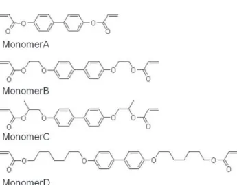
Fig. 1 Chemical structure of RM monomers. Monomer B, C: proposed monomers [6] in this paper. Monomer A, D: reference monomers [6], [11].
A nematic LC having a negative dielectric anisotropy (Δε = −2.1 and Δn = 0.116) is used. The concentration of UV curable RM monomer (Fig. 1) for the total com-positions is 0.5 wt%∼1.0 wt% and a photo-initiator (Ben-zoin isopropyl ether) is doped for promoting its photo-polymerization reaction, mass concentration of 1% for the UV curable RM monomer.
After filling the LC composition into a cell in nematic phase, the cell is irradiated by UV light source using (Hg-Xe lamp) to polymerize the monomer under the application of electric field at room temperature. The intensity of UV light was 3 mW/cm2 (365 nm) and the irradiation time was
10 min. The applied voltage was 3 V, which is slightly larger than the threshold voltage of the LC composition.
Then the UV curable RM monomers are polymer-ized in a certain direction so as to produce a favorable pretilt, which is maintained even after removing the volt-age. A crystal rotation method was adopted for measuring the pretilt angle.
A He-Ne laser (632.8 nm) was used to characterize the electro-optical properties of the cell, which was sandwiched between a pair of crossed-polarizers as its, rubbing direction is posed 45◦ to the transmission axis. The dependence of transmittance on applied voltage and both response time of rising and falling for each PSVA-LCD-cell were measured. The response time was defined as the time for 90% of rela-tive change in its transmittance to initial state after a pulse of voltage was applied. The dependence of capacitance on applied voltage was measured by the impedance analyzer to detect a change of LC orientation under the applied field.
Durability for the alignment with a pretilt stabilized by polymerized monomer was evaluated by detecting a changes of optical properties after storage at 80◦C with field of 10 volts for 500 hours.
2.2 Measurement Method of Curing Speed Rate of RM Monomers
9wt.% of UV curable RM monomer (Fig. 1), 1 wt% of
Fig. 2 Schematic diagram of the method for measurement of shear modulus (G’) for the mixture comprising each RM monomer.
Polytetramethylene glycoldiacrylate (A-PTMG-65, Shin-Nakamura Chemical Co., Ltd.) and Benzoin isopropyl ether (TCI) as a photo-initiator which concentration was 1 wt% for UV curable monomer were homogeneously solved in DMF solvent without dissolved monomer after being stirred at 100◦C for 1 hour. A change of viscoelastic character-istics for the mixture during photo-polymerization reaction under UV irradiation was observed with 1% of shear strain after setting the mixture on the glass stage of Rheometer (Physica MCR-301, Anton Paar). The gap between the glass stage and its spindle (detector) was controlled to be 0.4 mm in distance. A chemical lamp (FL15BL, NEC Cor-poration) was used as an UV light source and the intensity was 0.3 mW/cm2 through the glass stage. The temperature
of the mixture comprising RM monomer on the glass stage was controlled to be at 25◦C. Figure 2 shows a schematic diagram of the method for measurement of shear modulus (G’) for the composition of RM monomer.
3. Results and Discussions
3.1 Characteristics of PSVA-LCD
Table 1 shows the results of tilt angle of each VA-LCD at zero fields. The tilt angle = 0◦ is defined as the direction for vertical alignment of LC to a glass substrate. A tilt an-gle of monomer-free VA-LCD cell was controlled only by the rubbed alignment layers. The tilt angles of PSVA-LCDs are larger than that of monomer-free VA-LCD. The tilt an-gles depend on the content of RM monomers so as to in-crease, the induced tilt angles according to the content of RM monomer. It is clearly shown in the Table 1 that an orientation of LC is supported by the polymer phase.
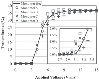
Figure 3 shows the dependence of relative capacitance of VA-LCDs in this study on its applied voltage. The PSVA-LCD by every RM monomer shows a lower Vth than that of monomer-free VA-LCD. Figure 4 shows the voltage-transmittance (V-T) characteristics for VA-LCDs. The PSVA-LCDs by Monomer B and Monomer C show lower Vths than that of Monomer-free VA-LCD. On the other hand, PSVA-LCD by Monomer A and Monomer D show the same or slight higher Vths than that of Monomer-free VA-LCD.
Fig. 3 The dependence of relative capacitance for VA-LCDs including PSVA-LCDs by various RM monomers (monomer content: 0.5 wt%) in this study on applied voltage.
Fig. 4 The dependence of transmittance for PSVA-LCD by each RM monomer (monomer content: 0.5 wt%) and monomer-free VA-LCD in this study on applied voltage.
Table 2 shows the response time of each VA-LCD mea-sured at 6 V of its driving voltage. The rise response time for PSVA-LCDs are effectively shorter than that of monomer-free VA-LCD in which alignment of LC is sustained by rubbed alignment layer. It is remarkable that those fall
re-Fig. 5 The dependence of transmittance for PSVA-LCDs by Monomer B (monomer content: 0.5 wt%, 1.0 wt%) and Monomer-free VA-LCD on applied voltage.
sponse times are also improved in case of PSVA-LCDs by Monomer B and Monomer C. It is supposed that characteris-tics such as elastic modulus, density and anchoring energy to LC and so on of polymer phase on the substrate affect those electro-optical characteristic and response characteristic of PSVA-LCD. PSVA-LCD by Monomer D shows slower fall response than the other PSVA-LCDs in this study. One of the cause might be that its tilt on the substrate is less sta-ble by the polymer phase which contains LC molecule in a larger amount because of its higher reaction rate in polymer-ization.
Figure 5 shows the dependence of monomer content on its V-T characteristics for PSVA-LCD by Monomer B. A larger content of Monomer B leads to a lower Vth in a threshold voltage range. Mobility of liquid crystal molecule in PSVA-LCD by larger content of Monomer B might be restricted in a higher voltage range on its V-T characteristics. Figure 6 shows the dependence of tilt angle on trans-mittance of several PSVA-LCDs at field off state in care-ful measurement because transmittance of PSVA-LCD is al-most proportional to its tilt angle in small pretilt region. In the aspect of content of RM monomer, a larger amount of monomer leads to a slower fall response and lower contrast ratio because the polymer phase might not affect an align-ment of LC only near the alignalign-ment layer but also that of LC a little way from the alignment layer [17].
Fig. 6 The dependence of tilt angle and transmittance of PSVA-LCD at field off state.
Fig. 7 Relative changes of transmittance on applied voltage for PSVA-LCDs (monomer content: 0.5 wt%) after storage at 80◦ with field for 500 hrs.
Figure 7 shows relative changes of transmittance on applied voltage for PSVA-LCDs after storage at 80◦C with field of 10 volts for 500 hours. Vertical axis indicates a rela-tive change value to the transmittance value before storage. The PSVA-LCDs by Monomer A and Monomer D show large changes of transmittance value around Vths. On the other hand, the PSVA-LCDs by Monomer B and Monomer C show little changes of transmittance value around Vths.
Figure 8 shows the estimated change value of the tilt angle (Δtilt) for PSVA-LCD by each RM monomer accord-ing to Fig. 6. It is shown that the Δtilt angles of PSVA-LCDs by Monomer A and Monomer D are larger than that of PSVA-LCDs by Monomer B and Monomer C. These results indicate that the RM monomers which have short length spacers give a better stability to the PSVA-LCDs. The sta-bility of PSVA-LCD depends on various factors, such as a kind of monomer material, its content, an applied voltage level during polymerization, UV energy for polymerization and so on. It is remarkable that PSVA-LCDs by Monomer B and Monomer C show a few image sticking phenomena
Fig. 8 The estimated value ofΔtilt angles for PSVA-LCDs (monomer content: 0.5 wt%) after storage at 80◦C with field for 500 hrs.
Fig. 9 Change of shear modulus (G’) of the mixture comprising each RM monomer during photo-polymerization by UV light irradiation.
comparing with PSVA-LCDs by Monomer A and Monomer D.
3.2 Reactivity of RM Monomer to UV Light and Charac-terization of the Polymer Phase
Figure 9 shows the shear storage modulus (G’) of the mix-ture comprising each RM monomer in DMF solvent with photo-initiator during photo-polymerization by UV light ir-radiation. G’ of the mixtures becomes higher and saturated on proceeding in polymerization. The saturated value of G’ for each RM monomer mixture depends on its chemi-cal structure, especially the spacer length of alkyl chain be-tween the core mesogen structure and reactive acrylic moi-ety. It is suggested in Fig. 9 that a longer alkyl spacer leads to a lower G’ for the mixture in the saturated value.
Relative change of G’ to the saturated value for the mixture comprising each RM monomer during photo-polymerization by UV light irradiation is shown in Fig. 10. It is indicated that the structure of alkyl spacer in RM monomer strongly affects its rate of polymerization. Fig-ure 8 suggests that better flexibility of the reactive acrylic
Fig. 10 Relative change of shear modulus (G’) to the saturated value for the mixture comprising each RM monomer during photo-polymerization by UV light irradiation.
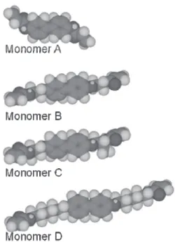
Fig. 11 Schematic diagram in 3D molecule model of chemical structure for each RM monomer.
moiety leads to faster reaction in polymerization because a longer alkyl chain results in better flexibility of the acrylic moiety. Besides, it is supposed that Monomer C shows a little slower reaction than Monomer B because methyl side chain in Monomer C might restrict the mobility of its methy-lene spacer.
Figure 11 shows the chemical structure in 3D mole-cule model for each RM monomer. The chemical structure of Monomer A suggests that molecular conformation of the acrylic moiety of Monomer A is very restricted and the poly-mer seems to be rigid without flexibility because the acrylic moiety directly bonded to core mesogen structure, which has a very little mobility in reaction of polymerization. A larger amount of UV light irradiation might be required for
age sticking in phase transition of chiral-nematic LCD [18]. On the other hand, the long C6 spacer between the core mesogen structure and reactive acrylic moiety in Monomer D gives a high reaction rate in polymerization and compar-atively low shear modulus of the polymer phase. It is sup-posed that the polymer phase might have less stable orien-tation of LC on the polymer-stabilized alignment layer be-cause containing LC molecule in a larger amount induced by its high reaction rate in polymerization and its flexibility caused by the long spacer in its chemical structure result in too soft polymer phase by Monomer D.
Suitable length of alkyl spacers both in Monomer B and Monomer C give a better reliability with less image sticking at high temperature with field and an improved reaction rate in polymerization.
4. Conclusion
Dependence of a display performance for PSVA-LCD on the chemical structure of RM monomer from which the polymer phase is made was studied in the aspect of the durability and reaction rate in this paper. Design of alkyl spacer between the core mesogen structure and reactive acrylic moiety in RM monomer is important factor for improvement of the display performance. PSVA-LCD by RM monomer which has a short alkyl chain such as ethylene or propylene shows a stable orientation of LC after storage at high temperature with field and good reaction rate in polymerization.
References
[1] D. Churchill and J.V. Cartmell, Display device containing minute droplets of cholesteric liquid crystals in a substantially continuous polymeric matrix, US Patent no.3,600,060, 1971.
[2] J.L. Fergason, “Polymer encapsulated nematic liquid crystals for display and light conrol applications,” SID’85 Technical Digest, vol.16, pp.68–70, 1985.
[3] J.W. Doane, N.A. Vaz, B.-G. Wu, and S. Zumer, “Field controlled light scattering from nematic microdroplets,” Appl. Phys. Lett., vol.48, no.4, pp.269–271, Jan. 1986.
[4] T. Gunjima, H. Kumai, S. Tsuchiya, and K. Masuda, Liquid crys-tal optical device and process for its production and method for its operation, US Patent no.4,834,509, 1989.
[5] D.-K. Yang and J.W. Doane, “Choresteric liquid crystal/polymer gel dispersions: Reflective display applications,” SID’92 Digest, pp.759–763, 1992.
[6] S. Niiyama and S. Tahara, Liquid crystal optical element and method for preparing the same, US Patent no.6,723,393, 2004.
[7] A. Takeda, S. Kataoka, T. Sasaki, H. Chiba, H. Tsuda, K. Ohmuro, T. Sasabayashi, Y. Koike, and K. Okamoto, “A super-high-image
quality multi-domain vertical alignment LCD by new rubbing-less technology,” SID’98, pp.1077–1080, 1998.
[8] S.H. Lee, S.L. Lee, and H.Y. Kim, “Electro-optic characteristics and switching principle of a nematic liquid crystal cell controlled by fringe-field switching,” Appl. Phys. Lett., vol.73, no.20, pp.2881– 2883, Nov. 1998.
[9] K. Sueoka, H. Nakamura, and Y. Taira, “Improving the moving-image quality of TFT-LCDs,” IDRC’97, pp.203–206, 1997. [10] T. Sasaki, K. Hanaoka, T. Kiyono, Y. Nakanishi, S. Tanuma, K.
Nakamura, Y. Inoue, M. Shibazaki, H. Tsuda, Y. Koike, Y. Tasaka, H. Yoshida, and K. Tashiro, Liquid crystal display device and man-ufacturing method therefor, Japan Patent no.4,014,934, 2007. [11] Y. Nakanishi, M. Shibasaki, K. Hanaoka, Y. Inoue, K. Tarumi, M.
Bremer, M. K-Memmer, S. Greenfield, and R. Harding, Liquid crys-tal display device, US Patent no.7,169,449, 2007.
[12] C.-Y. Huang, W.-Y. Jhuang, and C.-T. Hsieh, “Switching of polymer-stabilized vertical alignment liquid crystal cell,” Opti. Ex-press, vol.16, no.6, pp.3859–3864, March 2008.
[13] S. Kataoka, Liquid crystal display and method of manufacturing the same, Japan Patent P2006-145992A, 2006.
[14] D.-G. Seong, J.-J. Lyu, S.-B. Park, H. Kye, G. Seok, and M.-H. Kim, Liquid crystal display panel and method of manufacuturing the liquid crystal display panel, US Patent 2010/0231845A1, 2010. [15] C.-C. Hsieh, S.-F. Hsu, T.-S. Chen, C.-C. Lin, and C.-H. Pai,
Pho-tosensitive monomer, liquid crystal material having the same, liquid crystal panel and method for manufacturing thereof by incorporating the same, and electro-optical device and method for manufacturing thereof by incorporating the same, US Patent no.7,820,070, 2010. [16] Y.-J. Lee, Y.-K. Kim, S.I. Jo, J.S. Gwag, C.-J. Yu, and J.-H. Kim,
“Surface–controlled patterned vertical alignment mode with reactive mesogen,” Opt. Express, vol.17, no.12, pp.10298–10303, June 2009. [17] K. Maruyama, T. Houryu, and Y. Imura, “Realization of vertical alignment with low pretilt angle by polymer-stabilize technique,” J. Photopolym. Sci. Technol, vol.19, no.2, pp.157–162, May 2006. [18] S. Niiyama and N. Suehiro, Liquid crystal optical element and test
method for its boundary layer, US Patent no.6,674,494, 2004.
Remi Kawakami received the B.S. and M.S. degrees in Materials Science and En-gineering from Kyushu University in 2003 and 2005, respectively. She joined Asahi Glass Co., Ltd., Japan and has been study-ing LC/polymer composite technology. E-mail: [email protected]
Satoshi Niiyama received the B.E. and M.S. degrees from Kobe University in 1984 and 1986, respectively. He has been with Research Center of Asahi Glass Co., Ltd. Since 1986, working mainly in the field of polymer science and liquid crystal technology including composite materi-als comprising liquid crystal and polymer.
Yutaka Nakagawa received the B.S. and M.S. degrees in Applied Chemistry from Tokyo University in 1970 and 1972, respectively. He joined AGC Co., Ltd., Japan in 1972 and had studied LCD and material for electronic appli-cations. Since 2005 he has been studying LCDs for Optrex Corporation.
Yuji Soda received the B.S. and M.S. degrees in Industrial Chemistry from Kyushu Sangyo University in 1983 and 1985, respec-tively. He joined Optrex Corporation in 1985 and has been studying LCDs.