Micro-/Nano-Structuring and Modification to Enhance the Functionality of
Liquid-Infused-type Self-cleaning Surface
SUPERVISOR: PROFESSOR NOBUYUKI MORONUKI
Tokyo Metropolitan University Graduate School of System Design
Department of Human Mechatronics Systems
Student ID: 14989573
PHAN BINH NGUYEN
2017
I
Abstract
Self-cleaning surfaces that enable easy movement of liquid droplets are important for various industries as well as daily life. Various fine structures and low surface energy material coating have been tried to develop a self-cleaning surface. The modified structure is intended for air-trap in its vacant space beneath the droplets. Another approach is liquid-infused-type design which is inspired by slippery surface of nepenthes plant aiming at insect trap. It has been proved that its performance is better than that of the traditional one. However, the functional life is limited because a special liquid (lubricant) covering the surface drops off easily. Both of appropriate structural design and surface modification are potential solutions to improve the affinity between the surface and the lubricant which results in the improvement of the life.
It was proved that nanostructure has stronger affinity with the lubricant than microstructure under high shear conditions. The reason was considered that smaller vacant spaces of solid structure produce stronger capillary force to keep the lubricant.
However, the effect of the structural height to width ratio (aspect ratio, AR) on the affinity is not necessarily made clear. In addition, the higher AR structure has disadvantage of easiness of damage against mechanical contact. Thus an appropriate design that compromises the life and its mechanical durability should made clear. In addition, a simple, effective and scalable process becomes important considering its application in industry.
Cellulose nanofibers have amphiphilic property and expected to improve the affinity
of structured surface with the lubricant as well as the reinforcement of composite
materials utilizing their high strength. However, there are no preceding studies relating to
affinity improvement including its deposition process. Surface modification is one of the
options to change the affinity. Self-assembled monolayer (SAM) of
octadecyltrichlorosilane (OTS) can be used to modify silicon surface. Neither
II
deterioration of the original profile of solid structure nor shortening of lifetime is expected because it bonds strongly in spite of the nanometer thickness. Solution coating and drying is a simple process because of its simplicity and scale extension ability. However such modification of high AR nanostructure or combined structure of different materials has not been established. In addition, high AR structures are so flexible that the meniscus attraction during drying process cause stiction between them. It will be more difficult for OTS solution (OTS molecules) to infiltrate into deep and narrow spaces of the structures.
Thus, this study aims: (1) to make clear the effect of micro-/nanostructures including the modification on the affinity between the structures and the lubricant, (2) to make clear the definition of the functional life, (3) to make clear the effect of microstructure and cellulose nanofiber combination on the self-cleaning performance. Research works are discussed in 5 chapters. Main content of each chapter is as follows:
Chapter 1 introduces the background and the previous studies regarding self-cleaning surfaces, focusing on structural design of liquid-infused surfaces. Problem definition and aim of the research are shown.
Chapter 2 discusses the effect of the pillar structure design on the contact angle. High AR silicon nanopillar structures (aspect ratio up to 68) were fabricated on a silicon substrate using self-assembly of silica particles as etching mask and metal-assisted chemical etching (MACE). Effect of the AR on water contact angle (CA) was made clear and the AR larger than 28 is enough to obtain CA higher than 150º (superhydrophobicity).
However, the wettability changed with time due to oxidization or contamination on the surface. Water droplets have become sticky rather than slid on the surface.
Chapter 3 discusses the effect of surface modification on the self-cleaning functional
life. After defining the life, an original set up was built and the relationship between the
life and external load assuming rainfall was made clear. In addition to pillar structure,
finer silicon nanopore structures (average diameter of 500 nm, height up to 15 µm) were
fabricated through similar MACE with self-assembled silica particles mask. This original
III
hydrophilic surface was changed to hydrophobic one by modifying with OTS-SAM through solution coating and evaporation process. The modification conditions were changed to find the optimal one. Then the lubricant was retained in the structures to evaluate the life. The effect of the structure and modification on the life elongation was confirmed (increasing the AR by 5 times, the life was elongated more than 20 times). A tribometer was used to examine the effect of mechanical contact on the life. Effect of pore size and the lubricant on the damage of the solid structure was shown and design guideline for mechanical durability was made clear.
Chapter 4 discusses the deposition process of CNF on the structured silicon surface to extend the self-cleaning life. Microstructure can hold larger load than nanostructure while CNF structure is expected to improve only the affinity with the lubricant. Effects of the microstructure design (diameter=10 µm, height=15 µm, pitch=15-50 µm), CNF concentration (0-0.1 wt%) and etching process on the morphology of the CNF structure were made clear. Life was evaluated measuring the sliding angle of diethylene glycol (low surface tension liquid) after repeated water dash as an external load. It was confirmed that durable self-cleaning function was obtained with highly porous CNF layer on a structured silicon substrate. A new structural design was proposed aiming at self-repairing function and initial results were presented.
Chapter 5 summarizes the outcomes of the dissertation and shows the issues to be
improved in future.
IV
I
Content
Content ... I
1. Introduction ... 1
1.1 Background of self-cleaning surfaces ... 1
1.1.1 Solid-type self-cleaning surfaces... 8
1.1.2 Liquid-infused-type self-cleaning surfaces ... 10
1.1.2.1 Design guidelines ... 10
1.1.2.2 Wetting configurations ... 15
1.2 Changing the surface energy ... 18
1.2.1 Surface modification ... 18
1.2.2 Using hydrophobic material for structuring ... 23
1.3 Structuring processes ... 25
1.3.1 Top-down processes ... 25
1.3.1.1 Plasma etching ... 25
1.3.1.2 Metal-assisted chemical etching ... 26
1.3.1.3 Other etching processes ... 29
1.3.1.4 Replication ... 31
1.3.2 Bottom-up processes ... 32
1.3.2.1 Self-assembly of particles ... 32
1.3.2.2 Layer by layer (LbL) deposition ... 34
1.3.2.3 Sol-gel process ... 36
1.4 Lubricant ... 36
1.4.1 Perfluoropolyether (PFPE) ... 37
1.4.2 Other liquids ... 38
1.4.2.1 Ferrofluids ... 38
1.4.2.2 Water ... 38
1.4.2.3 Perfluorocarbon liquids ... 39
1.5 Problem definition and aim ... 40
1.6 Outline of the thesis ... 41
II
2. High aspect ratio silicon nanopillar structure and its wettability .... 45
2.1 Introduction ... 45
2.2 Experimental details ... 46
2.2.1 Fabrication procedure ... 46
2.2.2 Materials and devices ... 47
2.2.3 Evaluation... 51
2.3 Results and discussion ... 54
2.3.1 High aspect ratio silicon nanopillar structure ... 54
2.3.2 Effect of dry etching process before deposition of the Au layer ... 56
2.3.3 Effect of the thickness of the Au layer ... 60
2.3.4 Wettability of silicon nanopillar structures ... 61
2.4 Conclusion ... 63
3. Fabrication of high AR silicon nanopore arrays and surface modification aiming at long functional life ... 64
3.1 Introduction ... 64
3.2 Experiments for fabrication, modification and evaluation ... 66
3.2.1 Structuring process ... 66
3.2.2 Surface modification ... 68
3.2.3 Evaluation... 70
3.2.3.1 Surface structure and surface modification ... 70
3.2.3.2 The functional life ... 71
3.3 Results and discussion ... 74
3.3.1 High aspect ratio micro-/nano-pore structures ... 74
3.3.2 Self-assembled monolayer for high aspect ratio nanopore structures ... 76
3.3.3 Liquid-infused nanopore surfaces: initial self-cleaning performance ... 78
3.3.4 Liquid-infused nanopore surfaces: the functional life ... 79
3.3.4.1 Liquid dash condition ... 79
3.3.4.2 Mechanical contact condition ... 83
3.4 Conclusion ... 88
4. Combination of silicon microstructures and porous CNF structures to improve liquid-infused-type self-cleaning function ... 90
4.1 Introduction ... 90
4.2 Why cellulose nanofibers is chosen? ... 94
III
4.3 Experiments ... 95
4.3.1 Structuring processes ... 95
4.3.1.1 Silicon microstructuring ... 95
4.3.1.2 CNF deposition ... 99
4.3.2 Evaluation of functional lifetime ... 103
4.4 Results and discussion ... 105
4.4.1 Well-ordered CNF-silicon structures ... 105
4.4.2 Typical morphology of CNF structures – Procedure 1 ... 106
4.4.3 Porous CNF structures–Procedure 2 ... 110
4.4.4 Hydrophobization of the CNF-silicon structures ... 116
4.4.5 Durable self-cleaning function of the liquid-infused combined structured surfaces 118 4.5 Conclusion ... 120
4.6 New structural design and initial results ... 120
4.6.1 Combination of porous CNF structures and silica structures ... 120
4.6.2 Array of porous CNF micropillars ... 124
5. Conclusion and future work ... 125
5.1 Conclusion ... 125
5.2 Future work ... 127
References ... 128
Acknowledgments ... 147
IV
1
1. Introduction
This chapter gives a brief introduction of self-cleaning surfaces, requirements and processes to produce self-cleaning surfaces, focusing on liquid-infused-type self-cleaning surfaces. Problems of the liquid-infused surfaces and aim of this study are presented.
1.1 Background of self-cleaning surfaces
Self-cleaning surfaces, that enable easy movement of liquid droplets, are important for various industries as well as daily life. The self-cleaning surfaces are available in nature (Fig. 1.1). The most famous case is lotus leaf described by Barthlott in 1996 [1].
Its surface has fine structures at both micro and nanoscale (hierarchy) and low surface energy of waxes. Therefore water droplets rest on tips of the surface structure, have low adhesion with the surface and roll off easily [2–5]. This phenomenon, so-called “lotus effect”, also exists in nature with better performance. Figure 1.1b shows photo of a springtail, who lives in soil, in decaying material, and on plants, and SEM images of its structured surface with different magnification. Its surface has better performance, non- wetting with liquids of both high and low surface tension, than the surface of lotus leaf.
The reason is considered as its special structure with overhang profiles that is not popular
in nature [6, 7]. Figure 1.1c shows another case, a pitcher (nepenthes pitcher plant) and
its peristome morphology. Due to water condensation, rain, or nectar this structure is
covered by a thin liquid layer and the surface is activated to form the slippery surface
used to trap insect trap [8–11].
2
Fig. 1.1 Natural self-cleaning surfaces. a) Lotus leaf and its surface structure that includes both micro and nanostructure [1, 2]. b) Springtail skin and its special structure (re-entrant structure) with overhang profile. This smart skin can resist wetting by many
organic liquids and at elevated pressures [6]. c) A pitcher plant and its peristome morphology (arrows indicate direction toward the inside of the pitcher). [8, 11].
The relation between high mobility of liquid droplets and self-cleaning performance, the removal of particles (contaminant), was confirmed by Barthlott et al. (Fig. 1.2) [1]. In Fig. 1.2a, a mercury droplet rests on top of surface structure, air is entrapped beneath the droplet. Solid particles that are larger than the surface microstructures contact with tips of the structure and have low adhesion with the surface. Thus the particles which adhered to the surface of the droplet are removed with the droplet as it rolls off the surface (Fig.
1.2b). The schematic explanation is shown in Fig. 1.2c–d. The particles are removed on
structured surface while they are only redistributed on non-structured surface.
3
Fig. 1.2 Self-cleaning mechanism of the lotus surface. a) Mercury droplet on surface of a lotus leaf showing effect of structure on wettability (scale bar is 20m). b) Lotus effect (self-cleaning function). Solid particles (contaminant) are collected and removed by the droplet (scale bar is 50m). c-d) Self-cleaning mechanism: the particles are only
redistributed by water on non-structured surface (c), while they are removed on structured surface (d) [1].
Figure 1.3 shows wetting terminologies of solid surface [12, 13]. To quantify the
mobility of water droplet on solid surface, contact angle, contact angle hysteresis, and/or
sliding angle are used (Fig. 1.3a). The contact angle (CA,𝜃
𝑌) is the angle measured
through the liquid at interface of liquid–vapor and solid surface. The hysteresis is the
difference between advancing CA (𝜃
𝐴) and receding CA (𝜃
𝑅). The inclined angle, at
which a droplet starts to slide or roll off, is sliding angle (SA). Wettability of a solid
surface is identified from absolute wetting to no wetting based on contact angle of water,
a high surface tension liquid (Fig. 1.3b). When oil, low surface tension liquid, is used, the
4
corresponding terminologies are oleophilicity, oleophobicity and omniphobicity (or amphiphobicity) (Fig. 1.3c).
Fig. 1.3 Schematic representation of wetting terminology of solid surfaces [12, 13].
The development progress of self-cleaning surface was summarized clearly in Fig.
1.4 [14]. The timeline includes advances in theory, polymer and surface chemistry, as well as in the development of superhydrophobic surfaces and slippery liquid-infused porous surfaces (design of self-cleaning surfaces). Thomas Young initiates this area through explanation of solid-liquid interactions. The interactions were then extended by Wenzel and Cassie-Baxter.
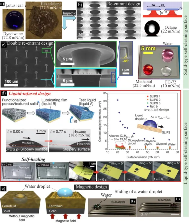
Fig. 1.5 shows wettability of lotus surface and the improvement with artificial self- cleaning surfaces. Artificial self-cleaning surfaces can be divided into 2 types: solid-type and liquid-type. A lotus leaf is hydrophobic and it loose the self-cleaning function when its operation environment has low surface tension liquid (oleophilic), condensation, or high temperature (Fig. 1.15a) [15–18]. While other solid-type self-cleaning surfaces with re-entrant design (single or double re-entrant) are omniphobic (Fig. 1.5b, c) [15, 19–23].
Solid surface Water droplet Air
YSolid su rface Air
ASA a)
b)
Solid surface Air
Solid surface
A= 0
Solid surface Air
Y< 90
o
Y> 90
oAir
Solid surface Air
Y> 150
oSolid surface Air
Y 180
oAbsolute wetting Hydrophilic Hydrophobic Superhydrophobic No wetting c)
Solid surface Air/Water
Y> 90
oOleophobic Oil
Solid surface
Air
Y> 90
oOmniphobic/Amphiphobic
Oil Water
Contact angle hysteresis:
RCAH = -
A
RContact angle:
Sliding angle: SA
YSolid surface Oleophilic
Oil
Y< 90
o5
Fig. 1.4 Timeline of major advances in the area of self-cleaning surface. The timeline includes advances in theory, polymer and surface chemistry, as well as in the development of superhydrophobic surfaces (SHSs) and slippery liquid-infused porous surfaces (SLIPS).
PDMS, polydimethylsiloxane; PTFE, polytetrafluoroethylene [14].
6
Fig. 1.5 Wettability of lotus surface and the improvement with artificial self-cleaning surfaces. a) Lotus surface wettability, hydrophobicity and oleophilicity [15]. To
improve: b)–c) Solid-type self-cleaning surfaces with re-entrant design exhibit omniphobicity; however, complex manufacturing processes are required due to overhang profile [15, 19–23]. d)–e) Liquid-type surface has an intermediate liquid layer
kept via surface structure (d) or magnetic field (e). The liquid-infused design shows
noticeable self-cleaning and self-healing ability [24–31].
7
However, complex manufacturing processes are required due to overhang profile of surface structures. Liquid-type self-cleaning surfaces are easier to produce. An intermediate liquid layer is kept via conventional surface structures (Fig. 1.5d) or magnetic field (Fig. 1.5e) [24–31]. In addition, liquid-infused-type surfaces exhibit noticeable functions such as self-healing that is extremely difficult to obtain with solid- type surfaces. Due to redistribution of the lubricant layer (Fig. 1.5d), physical damages or structured defects can be covered [24].
Fig. 1.6 shows self-cleaning performance of a liquid-infused surface, contaminating particles on the surface were removed by a water droplet [25]. Beside self-cleaning, liquid-infused surfaces have various functions, anti-icing, anti-fouling, drag reduction, etc. (Fig. 1.7) [24–30].
Fig. 1.6 Self-cleaning performance of liquid-infused surface. Contaminating particles on
a liquid-infused surface were removed by a water droplet [25].
8
Fig. 1.7 Various applications of liquid-infused surfaces: a) anti-icing, b) anti-fouling [26, 27].
1.1.1 Solid-type self-cleaning surfaces
Fine structures and low surface energy material coating are requirements for conventionally superhydrophobic surfaces. Special design of structure with overhang profiles is the third condition for omniphobic surfaces. These designs base on entrapped air in vacant spaces of structure beneath droplets. Figure 1.8 shows wetting states of an ideally flat surface and structured surfaces. The contact angle as a boundary condition of vapor solid liquid interface is determined via Young equation [32, 33]. At equilibrium condition (minimum free energy state):
𝑐𝑜𝑠𝜃
𝑌=
𝛾𝑆𝑉−𝛾𝑆𝐿𝛾𝐿𝑉
1.1
a)
b)
9
where 𝛾
𝑆𝑉, 𝛾
𝑆𝐿, 𝛾
𝐿𝑉are the interfacial energy at the interface of solid–vapor, solid–liquid, and liquid–vapor respectively. This is intrinsic contact angle of a solid material.
The Wenzel model describes the wetting state of structured surface with the homogeneous wetting regime (Fig. 1.8b, right schematic), vacant spaces of the structure are filled with liquid. In this case, contact angle is defined by Wenzel equation as follow [34]:
𝑐𝑜𝑠𝜃
𝑊= 𝑅𝑐𝑜𝑠𝜃
𝑌1.2
where 𝜃
𝑊is the apparent contact angle which corresponds to the equilibrium state, 𝜃
𝑌is the Young contact angle, 𝑅 is the roughness ratio, ratio of the rough surface area and its projected area.
The Wenzel model is not suitable for a heterogeneous surface. Cassie and Baxter proposed another model (Fig. 1.8b, left schematic). For this surface, contact angle is identified using Cassie-Baxter equation [35–37].
𝑐𝑜𝑠𝜃
𝐶= 𝑓
1𝑐𝑜𝑠𝜃
𝑌− 𝑓
21.3
where 𝜃
𝐶is the apparent contact angle which corresponds to the equilibrium state, 𝜃
𝑌is the Young contact angle, 𝑓
1is the area of solid–liquid contact and 𝑓
2is the area of air–
liquid contact per unit superficial area of the interface. In this state, there is a stable air layer in surface structure. This layer can be confirmed by dipping self-cleaning surface in a water container. The bright color of self-cleaning surface is usually observed. The reason is total reflection at an air layer between the surface and the water (Fig. 1.9). This air layer is usually called “plastron” [38–41].
The transition between 2 wetting states is usually from Cassie state to Wenzel state.
Many experimental and theoretical approaches have been tried to describe this transition,
however a general theory has not been obtaining [42-46].
10
Fig. 1.8 Wetting configurations of solid surfaces. a) Ideally flat surface: Young state; b) Structured surface: Cassie state and Wenzel state [32–37, 42–46].
Fig. 1.9 Air layer with bright color in superhydrophobic surface due to reflection of light [38].
1.1.2 Liquid-infused-type self-cleaning surfaces
Liquid-infused surface originally proposed by Aizenberg and co-workers is another solution to produce omniphobic surfaces. Fine structure was filled with a special liquid (a lubricant) to produce an intermediate layer and droplets of both high and low surface tension liquids can slide easily on this layer. CAH was smaller than 5 for different liquids with surface tension from 17.2 mN/m to 72.4 mN/m that showed good self-cleaning performance [24].
1.1.2.1 Design guidelines
Different aspects in design of liquid-infused-type self-cleaning surfaces are summarized in Fig. 1.10. They include surface structure, surface functionalization, and
Solid (S)
Liquid (L) Vapor (V)
YYoung state a) Ideally flat surface
LV
SV
SLCassie state
b)Structured surface Air
Wenzel state Liquid adhesion Weak
Strong adhesion Transition
Air layer Air
Water
11
lubricant. The design depends on operation conditions and applications and determines performance and durability of these surfaces.
Fig. 1.10 Different aspects in design of liquid-infused-type self-cleaning surfaces (inset image [47]).
General guidelines
The lubricant layer is the most important part of the surface, and its design guidelines
derived from requirements for the layer. These requirements include (1) the infused liquid
must infiltrate into and strongly adhere the substrate to produce a uniform layer, (2) the
infused liquid (B) and foreign liquid (A) dropped on the surfaces must be immiscible, and
(3) the infused layer must be not displaced by the foreign liquid. The first requirement is
satisfied by using fine structures (large surface area), low surface energy layer
(hydrophobicity, good chemical affinity) and the low surface tension liquid for easy
infusion. Perfuoropolyether (PFPE, F-(CF(CF
3)-CF
2-O)
n-CF
2CF
3), lubricant of vacuum
pumps, with low surface tension and immiscibility with many kinds of liquids, is usually
used to satisfy the second requirement [24, 48, 49]. The surface energy balance at the
interface of the lubricant, foreign liquids, fine structures, and air is critical for the third
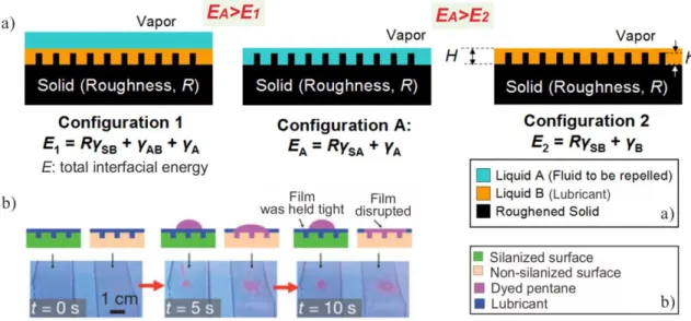
requirement. Therefore, configuration A must be unstable compared with configurations
12
1 and 2 in Fig. 1.11. The total free energy of configuration A must be larger than that of configurations 1 and 2. The quantitative conditions can be given by Eq. (1) and Eq. (2) (Fig. 1.11a, [24]):
𝐸
𝐴− 𝐸
1= 𝑅(𝛾
𝐵𝑐𝑜𝑠𝜃
𝐵− 𝛾
𝐴𝑐𝑜𝑠𝜃
𝐴) − 𝛾
𝐴𝐵> 0 1.4 𝐸
𝐴− 𝐸
2= 𝑅(𝛾
𝐵𝑐𝑜𝑠𝜃
𝐵− 𝛾
𝐴𝑐𝑜𝑠𝜃
𝐴) + 𝛾
𝐴− 𝛾
𝐵> 0 1.5 where 𝛾
𝐴and 𝛾
𝐵are the surface tensions for the external liquid and the lubricant, 𝛾
𝐴𝐵is the interfacial tension at the liquid-lubricant interface, 𝜃
𝐴and 𝜃
𝐵are the equilibrium contact angles of the foreign liquid and the lubricant on a flat solid surface, and 𝑅 is the roughness factor (the actual surface area per the projected surface area). From these equations, conditions of surface roughness (𝑅) and surface energy, that affects to factors of 𝑐𝑜𝑠𝜃
𝐴and 𝑐𝑜𝑠𝜃
𝐵, to obtain the balance can be given when the lubricant (𝛾
𝐵) and the foreign liquid (𝛾
𝐴) are chosen. Generally, low surface energy of solid surface is critical for stability of the lubricant layer. It was confirmed experimentally (Fig. 1.11b). Without surface modification (non-silanized surface), the layer was replaced by pentane droplet (low surface tension liquid). In contrast (silanized surface), the layer was stable and droplet of pentane could slide easily.
Fig. 1.11 Requirements for a stable lubricant layer. a) Schematic for quantitative
conditions. b) Experimental verification [24].
13 Guidelines for design of surface structures
Fig. 1.12 shows guidelines for structural design of liquid-infused surfaces that operate in high shear conditions. Three types of surface structures, microstructure (Fig. 1.12a), nanostructure (Fig. 1.12b), and micro/nanostructure (Fig. 1.12c), were used to evaluate effects of the structures on the self-cleaning performance (Fig. 1.12d). Contact angle hysteresis (CAH) was used to evaluate the performance and spin-coating was used to produce high shear stresses. Due to the lubricant loss, the performance was changed.
Finally, nanostructure is the most suitable structure because it has the highest capillary force to keep the lubricant against the stress (Fig. 1.12e) [50].
Fig. 1.12 Guidelines for structural design of liquid-infused surfaces that operate in high shear conditions. a) – c) SEM images of microstructure, nanostructure, and micro- nanostructure respectively. d) Changing of surface function versus different shear stress
(spin rate). e) Schematic explanation for the result in d) [49].
14
Fig. 1.13 Critical defect length or critical thickness of the lubricant layer that supports complete lubricant coverage. a) Definition of the critical defect length (inset is a SEM image of surface structure). b)-c) Effect of defect length or thickness of the lubricant layer on the complete wetting. D) SEM images of inverse opal structures with different roughness factor and different defect length. e)-f) Correlation between calculated values
and experimental values of the critical defect length and the critical thickness [51].
The critical defect length of surface structures, the maximum defect length that supports complete lubricant coverage, was proposed by Vogel et al (Fig. 1.13) [51]. A simple model correlates the critical defect length 𝑙
𝑐𝑟𝑖𝑡with the thickness of the lubricant layer ℎ and the contact angle of the lubricant on the solid substrate (Fig. 1.13a):
𝑙
𝑐𝑟𝑖𝑡=
2ℎ𝑡𝑎𝑛(𝛼/2)
1.6
15
From this equation, the critical thickness of the lubricant layer (minimum thickness of the lubricant layer that ensure complete lubricant coverage) is calculated as:
ℎ
𝑐𝑟𝑖𝑡= 𝑙
𝑐𝑟𝑖𝑡𝑡𝑎𝑛(𝛼/2) 1.7
Fig. 1.13b shows wetting of the lubricant with different defect length (thickness of the lubricant layer is fixed). The solid structure is exposed when defect length is larger than the critical value. The same problem occurs when thickness of the lubricant layer is smaller than the critical thickness (Fig. 1.13c). This exposure leads to pinning of liquid droplets. Fig. 1.13d and inset in Fig. 1.13a show SEM images of inverse opal structures.
The roughness factor (R) and defect length of these structures were controlled to verify the proposed model. Fig. 1.13e compares statistically measured mean defect lengths (color lines) to the calculated critical defect length (black line). Fig. 1.13f shows correlating experiment with theory to predict the complete wetting of the lubricant (spin- coating was used to change the lubricant layer thickness).
1.1.2.2 Wetting configurations
Because of the existence of the lubricant layer, wetting configuration of liquid-infused surfaces is quite different from solid-type surfaces. When the lubricant layer is stable, there are 4 states of a droplet on liquid-infused surfaces as shown in Fig. 1.14 [47, 52].
The droplet (red) resting on a micropillar array (blue) is surrounded by an annular wetting
ridge and a liquid three phase contact line (liquid-TPCL) exists (Fig. 1.14a, c). The liquid-
TPLC is the line at which the air, drop, and lubricant meet. The lubricant (yellow) does
not cloak (Fig. 1.14a, c) or it may cloak (Fig. 1.14b, d) the drop. Cloaking phenomenon
leads to much loss of the lubricant during operating process of these surfaces. When the
droplet contacts directly with the solid structure (Fig. 1.14c, d), it has high adhesion with
the surface and solid three phase contact line (solid-TPCL) exists. The solid-TPCL is
where the substrate, drop, and lubricant meet. Without solid-TPCL, the droplet that
separates with the solid structure has low adhesion with the surface (Fig. 1.14a, b).
16
Droplets on lubricant-infused surfaces can exhibit zero, one, or two three-phase contact lines. Generally, the wetting state with liquid-TPCL and no solid-TCLP (Fig. 1.14a) is the most preferable case due to its advantage from point views of initial self-cleaning performance and functional life. Quantitative conditions for this state are:
𝛾
𝐷< 𝛾
𝐷𝐿+ 𝛾
𝐿1.8
and 𝛾
𝑆𝐷> 𝛾
𝑆𝐿+ 𝛾
𝐷𝐿1.9
where
DL–interfacial tension between the drop and the lubricant;
SD–interfacial tension between the surface and the drop;
SL–interfacial tension between the surface and the lubricant.
Drepresents the surface tension drop–air and
Lthe surface tension lubricant–
air.
Fig. 1.14 Possible wetting configurations of liquid-infused surfaces when the lubricant layer is kept tight. (a, c) The droplet (red) resting on a micropillar array (blue) is surrounded by an annular wetting ridge that may end in a pulled-up liquid three phase contact line (liquid-TPCL). The lubricant (yellow) does not cloak (a, c) or it may cloak (b, d) the droplet. The liquid-TPLC is the line at which the air, drop, and lubricant meet,
and the solid-TPCL is where the substrate, drop, and lubricant meet [52].
Solid structure (S)
pinning points Strong adhesion
D)
Cloak B)
a) b)
c) d)
Droplet (D) Lubricant (L)
M u c h l o s s o f lu b ri c a n t
<
No pinning
17
Fig. 1.15 Confocal images of vertical sections through a liquid droplet placed on lubricant-infused surfaces and SEM images of corresponding surface structures. a) Micropillar surface (black rectangles). Cloaking of drops (a) or no cloaking (b). FC70,
decanol were used as lubricants. (a) Fluorescence signals (yellow) of FC70 and the reflection of light from the lubricant-air interface (cyan). (b) Fluorescence signals (yellow) of decanol. c) The shapes of the lubricant-air and droplet-lubricant-substrate interfaces of different droplets: water, hexadecane. Color code: Droplet-red; lubricant- yellow; reflected light-cyan; air-black. d) The existence of solid-TPCL. e) SEM images
of corresponding surface structures [52]
18
Schellenberger et al. used laser scanning confocal microscope to image the droplet- lubricant interface and the shape of droplets [52]. Cloak or no cloak was confirmed when FC70 and decanol were used as lubricants and water was used as external liquid (Fig.
1.15a, b). High magnification images of the droplet-lubricant-solid structure interface were shown. Water droplet and solid surface was not contact directly and there was a thin lubricant layer between them, no solid-TPCL. The shape difference of the lubricant layer at drop position and no drop position confirmed the formation of the wetting ridge (Fig.
1.15c). The existence of solid-TPCL was confirmed through the image of the water- decanol-solid structure interface (Fig. 1.15d).
The requirements of design and the wetting configurations of the liquid-infused surfaces were presented. Next, we will discuss how to respond the conditions.
1.2 Changing the surface energy
Many of conventional materials used for structuring are hydrophilic, surface modification (or hydrophobization) therefore is necessary to produce self-cleaning surfaces. The critical points here include adhesion of the coated layer with the modified surface, and thickness of the layer. Weak adhesion leads to short life of the layer. The thickness affects to the original profile of the modified structure, especially nanostructures. Hydrophobic bulk material, e.g. silicone, carbon nanotube, can be used rather than using surface modification.
1.2.1 Surface modification
There have been 2 main approach for surface modification, chemical modification, e.g. self-assembled monolayer (SAM) or polymer grafting, and physical modification, e.g.
deposition of fluorocarbon. Low surface energy layers produced by chemical
modification have stronger bond with modified surface and significantly smaller
19
thickness comparing with that produced by physical modification (Fig. 1.16a) [53-60].
The problem of the chemical method is more difficult to control. Molecules used to modify can be polymerized to form long-chain molecules with micro size that deteriorate the morphology of the modified structure [53, 61-63]. Fig. 1.16b shows the result of both modification processes for comparison, SAM of octadecyltrichlorosilane (OTS) and deposition of PTFE [60].
We will focus on chemical modification process due to its advantages. Various organosilanes have been used to produce SAMs. The formation mechanism of SAMs is shown in Fig. 1.17a [64, 65]. It was found that when the water content is very low, incomplete monolayers are formed; however, too much water results in silane polymerization in the bulk solvent phase and roughening of the resulting layer [66-69].
Fig. 1.17b and 1.17c show AFM images of silane modified substrates [66]. These images confirm the formation of the SAM (Fig. 1.17b) and the multilayer structure (Fig. 1.17c).
A special case of multilayer formation is shown in Fig. 1.17d [61]. Nanosheet structures
of OTS was formed, thus the surface exhibits very large water contact angle (154).
20
Fig. 1.16 Comparison between chemical modification (using SAM) and physical modification (using fluoropolymer). a) Schematic comparison: chemical modification (SAM) has stronger bond with the substrate and smaller thickness than that of physical modification [52-58]. b) AFM images and cross-section: a fluoropolymer (PTFE) layer (left) and SAM of octadecyltrichlorosilane (OTS) deposited on silicon substrates [60].
Substrate
Self-assembled monolayer (SAM) Fluoropolymer
Strong covalent bond (chemical adsorbtion)
Weak van der Waals bond (physical adsorbtion)
>10 nm Water
droplet
CH
3CF
2CF
3Reduction of end group
surface energy Water
droplet a)
b)
Physical modification Chemical modification
1 nm
21
Fig. 1.17 Formation of SAMs and multilayer structures. a) Schematic explantion for SAM and multilayer formation [64]. b)–c) AMF images of modified substrates confirm the SAM and multilayer formation, respectively [66]. d) A special multilayer structure:
SEM images and photo of water contact angle on this surface [61].
And the effectiveness of SAMs depends on the end groups and chain length of
organosilane molecules. It was proved that CF
3group has the smallest surface energy
(Fig. 1.16a) [55]. Fig. 1.18 shows effect of chain length and end groups of the
organosilane on the wettability of paper (Gel Blot). By using trichlorosilane with the
longest fluorinated alkyl chain and CF
3end group, hydrophilic Gel Blot paper was
modified to omniphobic paper. CAs of liquids with surface tension from 82.6 mN/m to
27.4 mN/m (Hexadecane) were higher than 120. In contrast, by using
methyltricholorosilane with short chain and CH
3end group the modified paper was fully
wetted by Ethylene glycol (46.3 mN/m) [70].
22
Fig. 1.18 a) Effect of chain length and end group of the organosilane on the wettability of paper: “C
1H”, CH
3SiCl
3; “C
10H”, CH
3(CH
2)
9SiCl
3; “C
8F”, CF
3(CF
2)
5CH
2CH
2SiCl
3;
“C
10F”, CF
3(CF
2)
7CH
2CH
2SiCl
3; “C
12F”, CF
3(CF
2)
9CH
2CH
2SiCl
3; C
12Fis the trichlorosilane with the longest fluorinated alkyl chain that is currently commercially available. Inset is SEM image of Gel Blot paper with native structure. b) Time-sequence
images of a drop of heparinized human blood rolling down on the paper functionalized with C
10F(side view: right; front view: left). The tilting angle is 30° [70].
For the SAM process, 3 deposition methods are usually used, solution deposition,
chemical vapor deposition, and contact printing (Fig. 1.19) [71-75]. Solution deposition
is preferable because of its simplicity and its scale extension ability. Its disadvantage is
23
deformation of modified structures due to meniscus force (attraction) of the solution during drying process.
Fig. 1.19 Typical processes to deposit SAM: a) Solution deposition (simple, easy for scale extension); b) Vapor deposition; c) Contact printing [71-75].
1.2.2 Using hydrophobic material for structuring
Spray-cast polymer-clay composite films were prepared using anaerobic acrylic adhesives to create fractal-like structure (Fig. 1.20a) [76, 77]. Water contact angle hysteresis of this film was smaller than 6, which shows good self-cleaning function.
After abrasion with sandpaper (Fig. 1.20b), the film still remained its performance with water CAH of smaller than 15 because its surface energy was not changed despite having considerable damage of its structure.
Fig. 1.20 An organoclay-polymer nanocomposite before and after abrading with sand paper, the arrows indicate wear marks [76].
Silicone nanofilaments (SNF), another polymer, can be deposited on a substrate to produce superhydrophobic surface [78]. Fig 1.21 (left) show SEM images of SNF grown
Substrate
Substrate Substrate Stamp Ink Controlling of
temperature, pressure Solution
a) b) c) Force
a) b) Wear mark
24
in toluene onto a silicon substrate by simply regulating the water concentration during hydrolysis and condensation of trichloromethylsilane (TCMS). This surface exhibited perfect hydrophobicity, water contact angle hysteresis of 0, and there was no adhesion with a water droplet (Fig. 1.21, right). Surface modification is not necessary in this case.
Fig. 1.22 shows pillar array of single-walled carbon nanotube (SWNT) fabricated by controlled synthesis of SWNT over a templated silicon substrate. This surface exhibited superhydrophobicity (water CA=160, photo of a water droplet on the right side) without further surface modification [79, 80].
Fig. 1.21 Perfectly hydrophobic surface made by growing silicone nanofilaments on a silicon substrate [78].
Fig. 1.22 Pillar array of single-walled carbon nanotube (SWNT) on a silicon substrate and photo of water droplet on the surface (CA=160) [79].
Perfectly hydrophobic surface
Water droplet No adhesion
CAH = 0
o50 nm
500 nm
SNF surface
25 1.3 Structuring processes
Generally methods used for structuring of conventional self-cleaning surfaces can be used to prepare liquid-infused surfaces. There are mainly 2 categories: top down or bottom up. With the top down processes, the accuracy of structures depends on that of machine or mask. Lithography, etching, cutting, and replication belong to this group [81, 82]. Conversely the bottom up processes base on the self-organizing principle [83–85].
Self-assembly of fine particles, layer by layer deposition, or sol-gel process are in this category. More detail discussion of each process will be shown in the next section 1.3.1 Top-down processes
1.3.1.1 Plasma etching
Plasma etching is a popular process used to fabricate integrated circuits (IC).
Microscopic features can be etched into surface of semiconducting materials, e.g. silicon, through chemical reaction or physical bombardment to produce efficient function for using in electronic devices, microelectromechanical systems (MEMS). To produce regular structures, etching mask is critical. That can be made by using lithography processes (Fig. 1.23a, [86]) or lithography-free processes (Fig. 1.23b, [87]). In high magnification view of Fig. 1.23a, silicon micropost structure was infused with a lubricant to produce the liquid-infused surface. In Fig. 1.23b, a silicon nanopillar array (after coating of low surface energy material) exhibited high water repellency (top right inset).
The limitations of this etching process are need of complicated device for etching and
difficulty in fabrication of high aspect ratio (height per diameter) structure.
26
Fig. 1.23 Silicon structures fabricated by using plasma etching with patterning of photolithography (a) and lithography-free (b) [86, 87].
1.3.1.2 Metal-assisted chemical etching
Metal-assisted chemical etching (MACE) is a site-selective etching process produced by a catalyst reaction at the interface between noble metal and silicon [88]. Figure 1.24 shows a mass transport model of MACE using a thin metal film as a catalyst [89]. First, Si atoms at the interface of the metal layer and Si substrate are oxidized, forming a porous Si layer. Through this layer, hydrofluoric acid (HF) can diffuse to the bulk Si to facilitate the dissolution. Then, the reactants and byproducts also diffuse through the porous layer.
The overall reaction is [88, 90, 91]:
Si + H
2O
2+ 6HF 2H
2O + H
2SiF
6+ H
2 1.10
Fig. 1.24 Mass transport model of metal-assisted chemical etching when using metal thin film for catalyst [89].
Porous layer Si
Site-selective direction
Si
Catalyst HF/H O
2 2Metal pattern
27
To produce ordered structures, patterning of the metal layer is critical. Sphere lithography, interference lithography, anodic aluminum oxide (AAO) mask and other methods were used to deal with this issues [92-97]. Fig. 1.25a shows a fabrication procedure of MACE using sphere lithography and reactive ion etching to produce a particle mask and a well-order, high aspect ratio nanopillar structure as result [92]. Arrays of vertically aligned sub 10nm diameter silicon nanopillars were fabricated using AAO mask (Fig. 1.25b) [95]. Fig. 1.25c shows an irregular silicon structure etched by using a thin, porous gold layer for catalyst. After surface modification, the superhydrophobic surface was obtained but water drops had high adhesion with this surface [97].
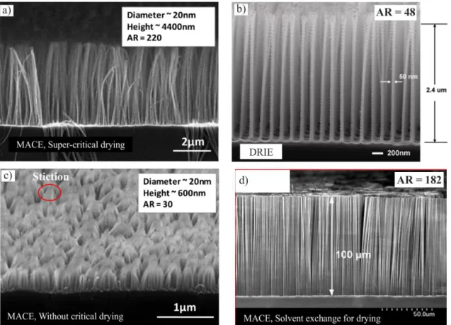
Fig. 1.26 shows aspect ratio comparison between MACE structures and deep RIE structures. An extremely high aspect ratio (220) nanostructure was fabricated in short time with super-critical drying (Fig. 1.26a) while the highest AR obtained using deep RIE was around 48 (Fig. 1.26b) [98-101]. However super-critical drying is complicated.
Without this drying process, the free-ends of nanopillars got together to form stiction at
small AR (30) (Fig. 1.26c) [98]. By using solvent exchange (high surface tension liquids
are changed to low surface tension liquids), the stiction was limited and high AR
nanostructure was obtained (Fig. 1.26d) [102]. Other processes were tried to reduce the
stiction [103, 104]. This ability is potential because high aspect ratio nanostructures with
extremely high surface area are expected to much enhance surface functions such as
lubricant retaining.
28
Fig. 1.25 Patterning methods. a) Sphere lithography (particle mask) [92]. b) AAO mask
[95]. c) A porous Au layer was used as catalyst without mask [97].
29
Fig. 1.26 Aspect ratio comparison between MACE structures and deep RIE structures.
a) MACE structure with super-critical drying [98], b) One of the highest aspect ratio fine structures fabricated using deep RIE [99], c) MACE structure without super-critical
drying. The free-ends of nanopillars got together to form stiction [98]. d) Limitation of stiction by using solvent exchange [102].
1.3.1.3 Other etching processes
Beside silicon, other materials can be etched using plasma, e.g. cellulose-based
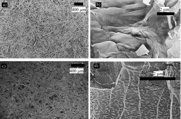
substrates, polymer substrates [105–108]. Fig. 1.27 shows SEM images of commercial
paper with microfiber structure etched by using oxygen plasma etching. Nanostructure
was produced on surface of cellulose microfibers (Fig. 1.27d). After surface modification
with PTFE deposition, hydrophilic surface of paper was changed to superhydrophobic
one.
30
Fig. 1.27 Commercial paper with microfiber structure was etched by using oxygen plasma etching. a)-b) Original surface. c)-d) 60 min etching (after surface modification
with PTFE) [105, 106].
The effects of plasma etching on surface structure of several cellulose-based substrates have been studied [105, 106]. Nanostructure was produced on the microfibers of the cellulose substrate by selective plasma etching (Fig. 1.27). Amorphous portions of the cellulose are selectively etched in an oxygen plasma. The chemical reactions are [ ]:
𝑃 + 𝑂
∗→ 𝑃
∗+ 𝑂𝐻 1.11
𝑃
∗+ 𝑂 → 𝑃
′𝑂 + 𝐶𝑂 ↑, 𝐶𝑂
2↑ 1.12 where 𝑃 represents a cellulose macromolecule. 𝑃
∗and 𝑃
′are radical sites of cellulose.
𝑂
∗and 𝑂 are oxygen radical and oxygen atom respectively.
c) d)
a) b)
31 1.3.1.4 Replication
Replication process is one of the simplest reproducible methods to prepare structured surfaces. This method uses a master as a replication template to replicate the features, followed by peeling off the templates [109]. Fig. 1.28 shows two-step replication process for creating replicas of nanostructured surfaces with high-aspect-ratio features [110]. The replicated structure is geometrically indistinguishable from the master. Scale extension of structured surfaces can be obtained by using this process.
Fig. 1.28 Two-step replication process for creating replicas of nanostructured surfaces
with high-aspect-ratio features. a) SEM image of a silicon master (posts: height 8 m,
32
diameter 250 nm). b) Liquid PDMS precursor is poured onto the master, treated with an anti-sticking agent, and cured. c) The cured PDMS is peeled off from the master. d) The negative PDMS mold, which contains an array of high-aspect-ratio wells corresponding to the posts of the positive master, is surface-treated with an anti-sticking agent. e) SEM image of the PDMS mold, revealing the high-aspect-ratio wells. f) Liquid precursor is poured onto the negative PDMS mold and cured. g) The PDMS mold is peeled from the
cured positive replica. h) SEM image of a replica. The replicated structure is geometrically indistinguishable from the master shown in a) [110].
1.3.2 Bottom-up processes 1.3.2.1 Self-assembly of particles
An ordered structure of fine particles can be obtained via the self-assembly process, without need of any complex control. A suspension that contains particles is spread on a hydrophilic substrate using dip-coating, spin-coating, Langmuir-Blodgett film, etc. [111- 114]. When the suspension is dried, the meniscus attraction between particles helps to produce a hexagonally-packed monolayer (Fig. 1.29). This layer can be used as a particle mask for metal patterning in MACE (Fig. 1.25a), or structure of self-cleaning surfaces (Fig. 1.30, [115, 116]), or a template to produce an inverse opal structure (Fig. 1.31 [51, 117-118]).
A hexagonally-packed monolayer of polystyrene (PS) particles on a silicon substrate was etched by using oxygen plasma (Fig. 1.30a, b, c). Size of the PS particles was reduced.
After surface modification step, the surface became superhydrophobic (water contact
angle of 168) [115]. In Fig. 1.30d-1.30f, a monolayer of PS particles on a PMMA
substrate was etched by using plasma in 2 steps, a re-entrant structure was then obtained
(Fig. 1.30f). The surface could repel liquids with different surface tension (water,
diiodomethane, and soya oil) after hydrophobization step (Fig. 1.30g) [116].
33
Fig. 1.29 Mechanism of self-assembly of particles (dip-coating process).
Fig. 1.30 Self-cleaning surfaces based on self-assembly of polystyrene (PS) particles and oxygen plasma etching. a)-c) SEM images (60°) of the size-reduced polystyrene (PS) particles and the water contact angle measurement on the corresponding modified
surfaces (insets). The diameters of PS particles and water contact angles on these surfaces were measured to be (a) 400 nm, 135°, (b) 330 nm, 152°, and (c) 190 nm, 168
[115]. d)-g) Self-assembly of PS particles on PMMA substrates combined with oxygen plasma etching to produce re-entrant structures that show omniphobicity [116].
In Fig. 1.31, a monolayer of PS particles was used as a template to fabricate an inverse monolayer structure. This structure was modified using SAM of (1H,1H,2H,2H- tridecafluorooctyl)-trichlorosilane and infused with a lubricant. Finally, a liquid-infused surface or liquid-type self-cleaning surface was obtained [51].
Evaporation of water
Capillary force Meniscus
force Particle
V
Aqueous suspension Hydrophilic substrate
A
A
Hexagonally-
packed structure
34
Fig. 1.31 Self-assembly of PS particles was used as template to produce inverse monolayer structures infused with lubricant for liquid-infused surfaces. a) Construction
scheme: after assembly on the desired surface (1), the monolayer is backfilled with the silica precursor solution of tetraethylorthosilicate (TEOS) (2), and the template is combusted to produce an inverse structure composed of silica (3). Hydrophobization of
the surface with (1H,1H,2H,2H-tridecafluorooctyl)-trichlorosilane (4) the structure is then infused with the lubricant (DuPont Krytox 100) to form a stable lubricant film (5).
A liquid droplet immiscible with the lubricant will be effectively repelled (6). b) Inclined SEM images of the inverse monolayer structure (scale bar: 5 µm). c) Wettability of the solid surface and the liquid-infused surface that show their self-
cleaning performance [51].
1.3.2.2 Layer by layer (LbL) deposition
Layer by layer deposition, one of thin film fabrication techniques, is a self-assembly
process. By depositing alternating layers of oppositely charged materials, the films are
produced. Various techniques can be used for the depositing process such as immersion,
spin-coating, spray-coating, etc. The main advantages include simplicity, applicability for
various materials, large area deposition. Especially, thickness of the film can be controlled
35
ideally with 1 nm resolution [119–121]. This ability is useful for liquid-infused surfaces because it reduces the degree of pinning of droplets due to fluctuation of structure height.
Fig. 1.32 shows the LbL process using negatively charged silica nanoparticles and positively charged polyelectrolyte to form nanoscale liquid-infused surfaces [120]. On these surfaces, water droplets and octane droplets had very small sliding angle of 2 that express good self-cleaning performance.
Fig. 1.32 LBL nanoscale lubricant-infused surfaces. a) Schematic illustration of the LbL process. Negative charges are introduced to the substrate (i) and subsequent layers of positively charged polyelectrolyte (ii) and negative charged silica nanoparticles (iii) are
adsorbed to form a hybrid thin film (iv) that can be calcined to remove the polymer layer (v). After covalently functionalizing the surface with fluorinated silanes (vi), a
lubricant is wicked into the structure (vii), rendering the surface non-adhesive and allowing for a secondary immiscible liquid to slide off the substrate with ease (viii). b)
SEM images after different deposition cycles on a glass substrate, taken after
36
calcination to remove the polymer layers. c-d) Liquid repellency properties of the LbL surface with and without lubricant. Time-lapse images of a water (c) and octane (d) droplet show sliding under an angle of 2 on a lubricated substrate with 5 deposited
silica nanoparticle layers without getting pinned to the substrate [120].
1.3.2.3 Sol-gel process
The sol-gel method can be applied over a large area and on various shapes using conventional coating methods such as spray coating, spin coating, dip coating etc. [50, 122–124]. Small molecules are conversed into a colloidal solution (sol) that acts as the precursor for an integrated network (gel). To improve the adhesion of the sol−gel layer, the underlying substrate can be activated by plasma etching or by applying an adhesion promotion layer. In Fig. 1.33, aluminum sol-gel was coated on lens surface to produce nanostructure. After formation of liquid-infused surface, the lens could repel motor oil while remaining its transparency.
Fig. 1.33 a) SEM image of aluminum sol-gel coating on lens surface (curve substrate).
b) Mobility of motor oil on the solid structure surface and corresponding lubricant infused surface [50].
1.4 Lubricant
Depending on application, various liquids can be chosen as the lubricant. The lubricant can affect to the performance and the functional life of the corresponding liquid- infused surfaces.
a) b)
Lens Motor oil
500 nm
37 1.4.1 Perfluoropolyether (PFPE)
As presented in Section 1.1.2, PFPE liquids (commercial name: Krytox) are usually chosen as the lubricant. These liquids are fluorocarbon ether polymers of polyhexafluoropropylene oxide, with chemical formular:
F−(CF(CF
3)−CF
2−O)
n−CF
2CF
3where the degree of polymerization, n, generally lies within the range of 10 to 60 [125]. Choosing of lubricant is important for the self-cleaning performance and the functional life.
Various types of PFPE liquids were considered to control velocity of water droplets on liquid-infused surfaces that affects to self-cleaning performance (Fig. 1.34a) [1-24]. It was confirmed that increasing viscosity of the lubricant lead to decreasing the velocity.
Infusing structured surfaces with longer-chain liquids, such as Krytox 107 (smaller evaporation rate) is a simple method of increasing the lifetime of liquid-infused surfaces at elevated temperatures (Fig. 1.34b) [126].
Fig. 1.34 Effect of lubricant on velocity of water droplets or self-cleaning performance (a) and the lifetime at elevated temperature (b) [126].
a)
Decreasing velocity
b)
Increasing lifetime Longer-chain fluoropolyether
![Fig. 1.7 Various applications of liquid-infused surfaces: a) anti-icing, b) anti-fouling [26, 27]](https://thumb-ap.123doks.com/thumbv2/123deta/10133285.1967173/18.893.218.677.134.676/fig-various-applications-liquid-infused-surfaces-icing-fouling.webp)
![Fig. 1.17 Formation of SAMs and multilayer structures. a) Schematic explantion for SAM and multilayer formation [64]](https://thumb-ap.123doks.com/thumbv2/123deta/10133285.1967173/31.893.129.765.123.561/formation-sams-multilayer-structures-schematic-explantion-multilayer-formation.webp)
![Fig. 1.20 An organoclay-polymer nanocomposite before and after abrading with sand paper, the arrows indicate wear marks [76]](https://thumb-ap.123doks.com/thumbv2/123deta/10133285.1967173/33.893.133.768.740.962/organoclay-polymer-nanocomposite-abrading-paper-arrows-indicate-marks.webp)
![Fig. 1.21 Perfectly hydrophobic surface made by growing silicone nanofilaments on a silicon substrate [78]](https://thumb-ap.123doks.com/thumbv2/123deta/10133285.1967173/34.893.145.752.802.1038/perfectly-hydrophobic-surface-growing-silicone-nanofilaments-silicon-substrate.webp)
![Fig. 1.23 Silicon structures fabricated by using plasma etching with patterning of photolithography (a) and lithography-free (b) [86, 87]](https://thumb-ap.123doks.com/thumbv2/123deta/10133285.1967173/36.893.133.763.126.344/silicon-structures-fabricated-plasma-etching-patterning-photolithography-lithography.webp)
![Fig. 1.34 Effect of lubricant on velocity of water droplets or self-cleaning performance (a) and the lifetime at elevated temperature (b) [126]](https://thumb-ap.123doks.com/thumbv2/123deta/10133285.1967173/47.893.138.764.647.877/lubricant-velocity-droplets-cleaning-performance-lifetime-elevated-temperature.webp)
