MRI を用いた顎関節円板側方転位のリスク因子の研究
日本大学大学院歯学研究科歯学専攻 小日向 清美
(指導:本田 和也 教授,松本 邦史 助教)
目 次
1.
概 要………. 2
2.
緒 言………. 6
3.
対象および方法………. 7
4.
成 績………. 11
5.
考 察………. 12
6.
結 論………. 16
7.
謝 辞………. 18
8.
文 献………. 19
9.
表および図………. 23
基幹論文:
Kohinata K, Matsumoto K, Suzuki T, Tsunoda M, Hayashi Y, Araki M, Hashimoto K, Honda K. Retrospective magnetic resonance imaging study of risk factors associated with sideways disk displacement of the temporomandibular joint. Jounal of Oral Science (in press), 2016.
概 要
顎関節円板障害は,顎関節症の最も一般的な病態の一つである。日本顎関節学会の 顎関節疾患および顎関節症の分類では,顎関節内部に限局した顎関節円板の位置異常 ならびに形態異常に継発する関節構成体の機能的ないし器質的障害と定義されている。
主病変部位は顎関節円板と滑膜であり,関節円板転位,変性,穿孔,線維化などによ り,顎関節痛,雑音,顎運動障害などを引き起こす。顎関節症の国際的な臨床診断基 準である Diagnostic criteria for temporomandibular disorders(DC/TMD)において,顎関 節円板障害は,変形性顎関節症,亜脱臼とともに関節内の器質的異常を有する顎関節 疾患として分類されている。DC/TMD 判定基準において,顎関節円板障害や変形性顎 関節症は,疼痛が関連する顎関節症や亜脱臼と比べ,臨床症状からの正診率が著しく 低く,確定診断には,画像による評価が必要であるとされている。
磁気共鳴映像法(
MRI
)は,顎関節円板障害の評価において,最も信頼できる画像 検査法である。これまでMRI
を用いた顎関節円板,筋,骨や骨髄などの画像所見と臨 床症状の関連性について,多くの研究報告がなされている。MRI
矢状断像は,顎関節 円板の前後的位置評価や機能的評価に使用され,顎関節円板前方転位の発症リスク因 子について,いくつかの報告がある。Taskaya-Yilmaz
らは,外側翼突筋上頭の付着部位 に焦点を当て,顎関節円板前方転位症例では,外側翼突筋上頭が顎関節円板のみに付 着していることが多いと報告している。このことから,顎関節周囲組織の解剖学的特 徴が,顎関節円板障害の発症に大きな影響を及ぼしている事が考えられる。Matsumoto
らは,MRI 冠状断像を用い,下顎頭と下顎窩の形態的な適合性に着目し,両者の形態的な不調和が,顎関節円板前方転位のリスク因子となることを示した。一方,顎関節 円板側方転位については,この項目と明らかな相関を示さず,顎関節円板前方転位の 影響が大きいためであると結論付けた。そこで著者は,顎関節円板側方転位の潜在的 なリスク因子を見つけるため,まず,第
1
研究として前方転位のない顎関節円板側方 転位例(真性顎関節円板側方転位)を対象に,MRI
上のいくつかの評価項目を調査し た。次いで,第2
研究として,前方転位を伴う顎関節円板側方転位例を対象に,冠状 断像,軸位断像における計測評価を行った。対象は日本大学歯学部付属歯科病院において,顎関節症検査や矯正治療前検査など の目的で
MRI
検査を行った1,422
名の患者のうち,第1
研究では,条件に該当する片 側性真性顎関節円板側方転位を有する26
名とした(52顎関節;男性9
名・女性17
名,平均年齢
43.0
歳,範囲18-63
歳)。一方,第2
研究では,前方転位を伴う顎関節円板側方転位を有する
70
名とした(84
顎関節;男性17
名・女性53
名,平均年齢39.0
歳,範囲
18-77
歳)。第2
研究のコントロール群として,同様の年齢分布の顎関節円板側方転位を伴わない前方転位症例
20
名(20顎関節)を無作為に抽出した。MRI
検査にて顎関節円板の内外側的位置を正常位,内側転位および外側転位の3
群 に分類した。MRI
における評価項目は,第1
研究では,冠状断像における下顎頭と下 顎窩の形態適合性,冠状断像における下顎枝軸面と下顎頭内外側極を結んだ線(内外 側極間線)の交わる角度,軸位断像における下顎頭に対する外側翼突筋の角度の3
項 目とし,顎関節円板の内外側的位置(内側転位,正常位,外側転位)における,各評 価項目に差があるかを検討した。第2
研究では,このうち下顎頭と下顎窩の形態適合性を除いた角度計測の
2
項目において,顎関節円板の内外側的位置異常で差異がある かを検討した。第
1
研究では,下顎頭と下顎窩の形態適合性,冠状断像における下顎枝軸面と下顎 頭内外側極間線の交わる角度においては,いずれも群間の差を認めなかった。一方,軸位断像における下顎頭に対する外側翼突筋線維走行のなす角度において,
3
群間に有 意差を認めた。多重比較検定では,真性顎関節円板内側転位群では,本角度が正常群 より有意に大きく,逆に真性顎関節円板外側転位群では,これが小さい傾向がみられ た。これらの結果から,軸位断像における下顎頭に対する外側翼突筋線維走行のなす 角度は,下顎頭の移動方向を決め,両者の機能調和の指標であると考えられ,適切な 付着角度によって,顎関節円板の内外側的位置が適切に保たれていることが示唆され た。また,この角度の過大や過小は,顎関節円板側方転位の潜在的なリスク因子とな り得る可能性が示された。追加項目として行った第2
研究では,両計測項目において,群間の差はみられなかった。このことから,真性顎関節円板側方転位と前方転位を伴 う顎関節円板側方転位では,病態や発症メカニズムが大きく異なる可能性が高いと考 えられた。また,前方転位の存在による機械的外力の増加が,顎関節円板の内外側的 位置に影響すると考えられた。
以上のように,軸位断像における下顎頭に付着する外側翼突筋の機能方向は,顎関 節円板の内外側的位置の恒常性に関与し,この角度の過大や過小は,真性顎関節円板 側方転位の潜在的なリスク因子となる可能性が示された。一方,真性顎関節円板側方
転位と前方転位を伴う顎関節円板側方転位では,発症メカニズムや病態が大きく異な る可能性が示された。
本論文は,原著論文
Retrospective magnetic resonance imaging study of risk factors associated with sideways disk displacement of the temporomandibular joint. Jounal of Oral
Science (in press)
を基幹論文とし,これに前方転位を伴う顎関節円板側方転位例について,冠状断像,軸位断像における計測結果を新たな実験データとして加えることによ って総括したものである。
緒 言
顎関節円板障害は顎関節症の一般的な病態の一つで,顎関節症の国際的な臨床診断 基準である Diagnostic criteria for temporomandibular disorders(DC/TMD)において,変 形性顎関節症,亜脱臼とともに関節内の器質的異常を有する顎関節疾患として分類さ
れている1,2) 。
DC/TMD
判定基準において,顎関節円板障害や変形性顎関節症は,疼痛が関連する顎関節症や亜脱臼と比べ,臨床症状からの正診率が著しく低く顎関節円板 障害や変形性顎関節症の確定診断には画像評価が必要であるとされている2) 。
磁気共鳴映像法(
MRI
)は,顎関節円板障害の評価において,最も信頼できる画像 検査法である 3,4) 。これまでMRI
を用いた関節円板,筋,骨や骨髄などの画像所見と 臨床症状の関連性について,多くの報告がされている 5-8) 。MRI 矢状断像は,顎関節 円板の前後的位置評価や機能的評価に使用され,顎関節円板前方転位のリスク因子に 関連した報告がいくつかある 9,10) 。Taskaya-Yilmaz
ら 9) は,外側翼突筋上頭の付着部 位に着目し,関節円板前方転位例では,外側翼突筋上頭が顎関節円板のみに付着して いることが多いと報告している。このことから,顎関節周囲組織の解剖学的形態が,顎関節円板障害の発症に大きな影響を及ぼしていると考えられる。
Matsumoto
ら10) は,MRI
冠状断像における下顎頭と下顎窩の形態的な適合性に着目し,両者の不調和が顎 関節円板前方転位のリスク因子となることを示した。一方,顎関節円板側方転位につ いては,この形態的な適合性とは明らかな相関を示さず,顎関節円板前方転位の影響 が大きいためであると結論付けた。そこで著者は,顎関節円板側方転位の潜在的なリ スク因子を見つけるため,第1
研究として,前方転位を有さない顎関節円板側方転位例(真性顎関節円板側方転位)を対象に,顎関節円板側方転位のリスク因子となりう る項目について,画像評価および計測評価を行った。次いで,第
2
研究として,前方 転位を伴う顎関節円板側方転位例を対象に計測評価を行った。対象および方法
1.
対象 第1
研究日本大学歯学部付属歯科病院において,顎関節症検査や矯正治療術前検査などの目 的で
MRI
撮像を行った1,422
名の患者のうち,以下の条件に該当する26
名とした(52 顎関節;男性9
名・女性17
名,平均年齢43.0
歳,範囲18-63
歳)。1)
以下の条件すべてに該当する患者を対象とした。① 片側性の真性顎関節円板側方転位を有する(患側)。
② 反対側の顎関節では,顎関節円板の位置,形態異常がない(コントロール側)。
③ 臨床的には顎関節に症状を認めないか,または
DC/TMD
にて咀嚼筋痛障害のみで,両側顎関節に主たる症状を有さない。
2)
以下の条件に該当するものは事前に対象から除外した。① 片側あるいは両側の顎関節に骨変形 (骨棘,骨びらん,骨髄変性など),発育異常
(巨顎症,小顎症,顔面非対称など),顔面外傷,全身性関節炎 (関節リウマチ,
関節症性乾癬,痛風など)の既往がある。
②
18
歳以下である。③ 上下顎のどちらかに
2
歯以上の連続欠損がある。第
2
研究前方転位を伴う顎関節円板側方転位例を対象とし,第
1
研究と同様にMRI
撮像を行った
1,422
名の患者のうち,以下の条件に該当する70
名とした(84
顎関節;内側転位:20
関節,外側転位:64
関節;男性17
名・女性53
名,平均年齢39.0
歳,範囲18-77
歳)。コントロール群として,同様の年齢分布の顎関節円板側方転位を伴わない前方転位例
(
20
名20
関節)を無作為に抽出した。1) 疾患群について,以下の条件に該当する患者および顎関節を対象とした。
顎関節円板障害の症状の有無に関わらず,片側性あるいは両側性の前方転位を伴う 顎関節円板側方転位を有する。
2)
コントロール群について,以下の条件に該当する患者および顎関節を対象とし た。顎関節円板障害の症状の有無に関わらず,片側性の側方転位を伴わない顎関節円板 前方転位を有する。
3)
疾患群およびコントロール群の除外基準は,第1
研究の除外基準と同様とした。第
1,第 2
研究における患者データの使用は,日本大学歯学部倫理委員会で承認を受け(倫許
2008-24
),患者より口頭ならびに書面で承諾を得た上で行った。2. MRI
撮像条件第
1
,第2
研究ともに,3.0T MRI
(Achieva 3.0 T
;フィリップス,アムステルダム,オランダ)を用い,同一条件で撮像を行った。撮像シーケンスはスピンエコー法で,
プロトン密度強調条件(繰り返し時間/エコー時間(
TR
/TE
):1800 ms
/20 ms
,撮像範囲(
FOV
):130 mm × 130 mm
)の矢状断像および冠状断像,T1
強調画像条件(TR
/TE:426 ms/9 ms,FOV:220 mm × 220 mm)の軸位断像を撮像した。また,マトリ
ックスは
512 × 512,フリップ角は 90˚に設定した。矢状断像は,下顎頭の短軸に平行,
冠状断像は
Stehling
ら11) の基準に従い,下顎頭の長軸に平行に撮像した画像とした。また軸位断像は,フランクフルト平面に平行に撮像した画像とした。スライス厚は,
矢状断像と冠状断像で
3 mm,軸位断像で 5 mm
とした。3
.MRI
画像の評価第
1,第 2
研究においてMRI
画像を用いて以下の4 ~ 6
の項目の評価を行った。MRI
の評価は2
名の歯科放射線科医(経験年数:4年および12
年)がそれぞれ個別に行っ た。画像評価における両評価者の結果が相違した場合は,合議の上決定した。顎関節 円板の形態と位置の評価には,矢状断像および冠状断像を使用した。画像上の角度の 計測には,下顎頭中央でスライスされた冠状断像および軸位断像を使用した。4
.顎関節円板の評価第
1,第 2
研究ともに,矢状断像における顎関節円板の形態と位置の評価は,以下の判定基準を使用した10, 12) 。顎関節円板の形態は,
biconcave
あるいはeven thickness
を 正常,biconvex
,enlargement of posterior band
,enlargement of anterior band
,fold
,other
を異常とした。顎関節円板の前後的位置は,閉口時の顎関節円板中央狭窄部が,下顎 頭と関節隆起後方斜面の間にある場合を正常とし,顎関節円板後方肥厚部が下顎頭の 前方に位置する場合を前方転位とした。また,顎関節円板の内外側的位置の評価には,冠状断像を用い,補助的な評価として矢状断像を使用した。Liedbergと
Westesson
13) の 判定基準により,顎関節円板の内外側的位置は,冠状断像の下顎頭の内側極・外側極 を含む下顎頭上面を覆っている場合を正常位とし,顎関節円板が下顎頭の外側極,内 側極を覆っていない場合をそれぞれ内側転位,外側転位とした(Fig. 1)。5.下顎頭と下顎窩の形態評価
第
1
研究では,冠状断像を用い,下顎頭と下顎窩の形態評価を行った。Matsumoto
ら 10)の分類を用いて,下顎頭と下顎窩をそれぞれconvex,angled,flat
あるいはother
に分類した。さらに,下顎頭と下顎窩の形態適合性について,調和群(例:convex 型 下顎頭と下顎窩,angled
型下顎頭と下顎窩など)と不調和群(例:convex
型下顎頭とflat
型下顎窩,angled
型下顎頭とconcave
型下顎窩など)の2
つのグループに分類した10) 。
一方,前方転位を伴う顎関節円板側方転位例に対する本評価項目については,すで
に
Matsumoto
ら10)の報告で関連性は否定されているため,第2
研究においては本項目の評価を行わなかった。
6.
冠状断像と軸位断像における角度計測第
1,第 2
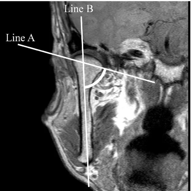
研究ともに,Virtual Place(AZE,東京,日本)を使用し,コンピュータ モニター上で計測をおこなった。計測項目は以下の2
項目とした(Fig. 2, 3
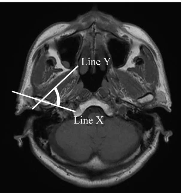
)。計測項目
1
:冠状断像における下顎枝軸面と下顎頭内外側極間線の交わる角度計測項目 2:軸位断像における下顎頭内外側極間線と下顎頭中央部における外側翼突 筋の走行に合わせた線の交わる角度(外側翼突筋の下顎頭付着角度)
角度計測は,
2
名の歯科放射線科医が2
回ずつ行い,計測値の平均値を統計分析に用 いた。7.統計処理
第
1
研究において,顎関節円板の内外側的位置(正常位,内側転位,外側転位)に 対する下顎頭と下顎窩の形態適合性について,カイ二乗検定を用いた。また,顎関節 円板の内外側的位置と2
種の計測項目計測値について,第1,第 2
研究ともに,一元配 置分散分析(ANOVA
)を用い,有意差が認められた場合は多重比較検定としてTukey
検定を用いた。統計学的有意水準は5 %
とした。成
績
第
1
研究1.
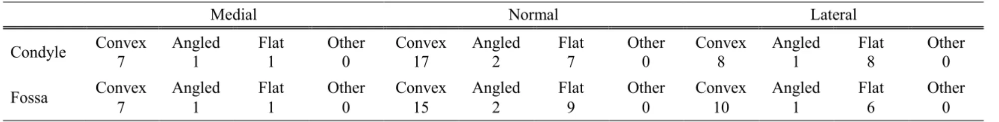
顎関節円板の内外側的位置に対する下顎頭と下顎窩の形態の分布をTable 1
に示す。下顎頭と下顎窩の形態に
other
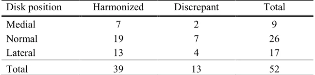
に分類されるものは認められなかった。顎関節円板の 内外側的位置関係と下顎頭と下顎窩の形態適合性の関係をTable 2
に示す。いずれも 有意差は認められなかった。2.
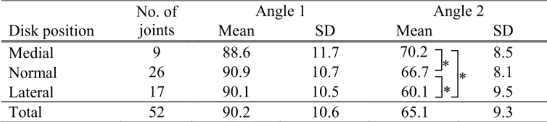
真性顎関節円板内側転位,内外側的正常位,真性顎関節円板外側転位例における,計測項目
1
と計測項目2
をTable 3
に示す。計測項目1
は,真性顎関節円板内側転 位,内外側的正常位,真性顎関節円板外側転位において,それぞれ88.6°
± 11.7,90.9°
± 10.7,90.1° ± 10.5 であり,3 群において有意差はみられなかった。計測項目
2
は,それぞれ70.2°
±8.5
,66.7°
±8.1
,60.1°
±9.5
であり,3
群間に有意 差がみられた(P = 0.012)。多重比較検定では,内側転位,内外側的正常位,外側転 位間のそれぞれに有意差を認めた(内側転位vs
正常位:P= 0.048,外側転位 vs
正 常位:P = 0.044,内側転位vs
外側転位:P = 0.019)。第
2
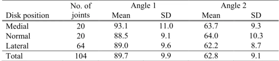
研究1.
前方転位を伴う顎関節円板内側転位,内外側的正常位,外側転位における,計測項 目1
と計測項目2
をTable 4
に示す。両計測項目について,3
群間の有意差はみら れなかった。考
察
第
1
研究の結果から,外側翼突筋の下顎頭付着角度が,真性顎関節円板側方転位の リスク因子である可能性が示された。これまで,顎関節円板前方転位と外側翼突筋の解剖学的位置や形態に関連が報告されており 9, 14),顎関節円板転位は顎関節と筋の機 能的不調和に起因するという仮説から本計測項目を対象とした。本研究で計測対象と した外側翼突筋は,
Murray
ら15) の報告によれば,二頭のうちの下頭であると考えられ る。外側翼突筋下頭の筋線維走行の方向は,下顎の水平方向への運動と密接に関連し ている 16)。したがって,外側翼突筋下頭と下顎頭間の角度は,下顎頭の移動方向を決 め,両者の機能調和の指標であると考えられる。第1
研究において,真性顎関節円板 内側転位例では,外側翼突筋の下顎頭付着角度が大きく,逆に顎関節円板外側転位例 では,これが小さい傾向がみられた。以上のことから,外側翼突筋下頭と下顎頭間の 適切な角度によって,顎関節円板の内外側的位置が適切に保たれていることが示唆さ れた。また,この角度の過大や過小は,顎関節円板側方転位の潜在的なリスク因子と なり得る可能性が示された。Foucart
ら17) は,顎関節円板障害の37%
に顎関節円板側方転位がみられ,4%
に真性顎関節円板側方転位がみられたと報告している。したがって,本研究は非常に希な病 態に着目したものである。Almăşanら18) は,前方転位を伴う顎関節円板側方転位例に ついて,いくつかの項目との関連性を調査したが,これまで,真性顎関節円板側方転 位を対象とした調査はほとんど行われていない。また,第
1
研究では,Matsumoto
ら10) が,顎関節円板前方転位のリスク因子とした下顎頭と下顎窩間の形態適合性を評価 項目とした。しかし,真性顎関節円板側方転位例について調査したが,下顎頭と下顎 窩間の形態適合性と病態に関連はみられなかった。それゆえ,下顎頭と下顎窩間の形 態適合性は顎関節円板の前後的位置の安定性に関与していると考えられた。Almăşan
ら18) は,冠状断における下顎頭内外側極間線と正中矢状面との角度を調査したが,顎 関節円板前方転位ならびに側方転位との関連はみられなかったと報告している。本研 究では,冠状断像における下顎枝軸面と下顎頭内外側極間線の交わる角度を評価した が,有意差は得られなかった。しかし,この評価項目は標準偏差が大きく,顎関節症 の病態に何らかの関与があるのではないかと考えられた。
第
2
研究で行った顎関節円板前方転位例の評価において,2
つの角度に関する評価項 目について,顎関節円板の内外側的位置による差はみられなかった。顎関節円板側方 転位について,これまで病因論についてほとんど報告はなく,前方転位と側方転位の どちらが先行して起こるかもわかっていない。顎関節円板前方転位例では,顎運動に 伴い,顎関節円板が下顎頭の移動による機械的な力によって圧迫を受ける。その結果 として,顎関節円板の内外側的転位が起こる可能性が考えられる。一方で,その頻度 は少ないと考えられるが側方転位に続いて顎関節円板前方転位が起こる可能性もある。本研究結果から,真性顎関節円板側方転位と前方転位を伴う顎関節円板側方転位では,
病態や発症メカニズムが大きく異なる可能性が高い。また,前方転位の存在による機 械的外力の増加が,顎関節円板の内外側的位置に影響すると考えられ,症例数を増や すことや経時的評価を行うことで,両者の病態や発症メカニズムを解明できると考え ている。
顎関節症のリスク因子として,悪習癖,歯ぎしり,咬合異常,心理的問題および解 剖学的要因などが関与している19-21) 。さらに,顎関節症の複雑な病態はさまざまな原 因によって引き起こされている19) 。本研究は,
MRI
を使用し,解剖学的特徴から顎関節円板側方転位のリスク因子について評価したが,いくつかの問題点がある。第一に,
真性顎関節円板側方転位例の対象数が少なかった。しかし,前方転位の影響を除外で きたことから,正確にリスク因子の選別ができたと考えている。第二に,本研究で評 価した外側翼突筋下頭は,顎関節円板に付着していない。つまり,外側翼突筋下頭は 間接的に下顎運動時の顎関節円板位置に影響を与えるため,顎関節円板の位置の恒常 性に直接影響しておらず,今後,MRI を多断面再構成することによって,外側翼突筋 上頭の評価を加える必要がある。第三に,顎関節円板の評価が質的評価であった。
Eberhard
ら22) による量的評価を行えば,より正確なリスク因子の探索が可能となると考えられた。今後,症例数や計測方法,計測項目,計測期間などをさらに改善し,顎 関節円板転位の原因やリスク因子を検討していきたいと考えている。
結 論
MRI
を用いて顎関節円板側方転位のリスク因子を調査するために真性顎関節円板側 方転位と前方転位を伴う顎関節円板側方転位例を検討した結果,以下の結論を得た。1.
真性顎関節円板側方転位では,冠状断像における下顎頭と下顎窩の形態適合性の良 否が,顎関節円板側方転位のリスク因子と予測したが,関連はみられなかった。2.
真性顎関節円板側方転位では,冠状断像における下顎枝軸面と下顎頭内外側極間線 の交わる角度を,顎関節円板側方転位のリスク因子と予測したが,関連はみられな かった。3.
真性顎関節円板側方転位では,軸位断像における下顎頭に対する外側翼突筋線維走 行のなす角度について,顎関節円板の内外側的位置(内側転位,正常位,外側転位)間で有意差を認めた。多重比較検定では,真性顎関節円板内側転位群では,本角度 が正常群より有意に大きく,逆に真性顎関節円板外側転位群では,これが小さい傾 向がみられた。
4.
前方転位を伴う顎関節円板側方転位例では,冠状断像および軸位断像における計測 角度について有意差はみられなかった。以上のように,軸位断像における下顎頭に付着する外側翼突筋の機能方向は,顎関節 円板の内外側的位置の恒常性に関与し,この角度の過大や過小は,真性顎関節円板側 方転位の潜在的なリスク因子となる可能性が示された。一方,真性顎関節円板側方転 位と前方転位を伴う顎関節円板側方転位では,発症メカニズムや病態が大きく異なる
可能性が示された。
謝 辞
本研究にあたり,格別な御指導と御高閲を賜りました本学歯科放射線学講座本田和 也教授ならびに直接研究を御指導いただいた松本邦史助教に謹んで感謝の意を表しま す。また,本研究に対して御協力いただいた歯科放射線学講座員各位に深く感謝申し 上げます。
本研究の一部は,平成
26
年度大学院歯学研究科研究費(学生分:小日向清美)の助 成により行われた。文 献