Electrochemical Na-insertion/extraction properties of
Sn−P anodes
Hiroyuki USUIa,b, Takuma SAKATAa,b, Masahiro SHIMIZUa,b, and Hiroki SAKAGUCHIa,b,*
aDepartment of Chemistry and Biotechnology, Graduate School of Engineering, Tottori University,
4-101 Minami, Koyama-cho, Tottori 680-8552, Japan
bCenter for Research on Green Sustainable Chemistry, Tottori University, 4-101 Minami, Koyama-cho,
Tottori 680-8552, Japan
Abstract
Thick-film electrodes of tin phosphides, Sn4P3 and SnP3, were prepared using a mechanical alloying
method followed by a gas-deposition method, and were evaluated as Na-ion battery anodes in an organic
electrolyte and ionic liquid electrolytes. The Sn4P3 electrode showed a better cycling performance in the
organic electrolyte compared with the SnP3 electrode and an Sn electrode. The performance of the Sn4P3
electrode was further improved by using ionic liquid electrolytes because of a uniformly formed surface
layer and resulting uniform sodiation/desodiation reactions on the electrode.
1. Introduction
Power generations based on renewable energy sources such as solar, wind, and geothermal are very
important to realize a low-carbon society. Na-ion battery (NIB) has a disadvantage compared with Li-ion
battery (LIB) in terms of the specific capacity of electrode and the energy density because of 2.4 times
larger ionic volume of Na+ than Li+. On the other hand, sodium resources are available everywhere and
much less expensive than lithium resources, which enables low-cost and large-scale production of NIB.
Thus, NIB is a promising substitute for LIB in large-sized stationary batteries for the renewable energies.
Komaba et al. have succeeded in bringing out an NIB anode of hard carbon a reversible capacity of 250−
300 mA h g−1 by a reversible Na-insertion into its nanopores.1 For a further high capacity, elemental
phosphorous (P)2 and tin (Sn)3 are promising candidates of anode materials because these elements show high theoretical capacities (P, 2596 mA h g−1; Sn, 847 mA h g−1
) based on alloying/dealloying reactions.
Anodes consisting of elemental P or Sn, however, generally show deterioration of an active material
layer and a resulting capacity decay by several ten cycles because these elements exhibit significant
volume increase in their Na-storage (Na15Sn4, 525%; Na3P, 490%).
Some researchers have developed Sn4P3 anodes.4-6 It has been recently reported that Sn4P3 showed a
synergistic Na-storage reaction where Sn and P atoms can react with Na to form Na15Sn4 and Na3P, and
that the resulting Na15Sn4 alloy acts as a conducting pathway to activate the reversible Na-storage
reaction of nonconductive Na3P particles while the well-dispersed Na3P phase provides a shield matrix to
prevent the aggregation of the Na15Sn4/Sn nanoparticles.
As new NIB anode materials, the authors have developed SnO,7 SiO,8 and TiO2(rutile).9 On the other
hand, the authors have demonstrated a utility of an ionic liquid electrolyte for a high-capacity silicon
anode in LIB: the electrolyte offered a better cycling performance of the anode by more homogeneous
surface layer generated by its cathodic decomposition compared with that of a conventional organic
electrodes in the organic electrolyte, and tried to improve the performance by applying the ionic liquid
electrolyte.
2. Experimental
Active material powders of Sn4P3 and SnP3 were prepared by a mechanical alloying (MA) method
using commercially available tin (Kojundo Chemical Lab. Co., Ltd. 325 mesh, 99.99%) and amorphous
red phosphorous (Wako Pure Chemical Industries, Ltd. 98.0%) with weight ratios of 4:3 and 1:3,
respectively. The mixtures of tin and phosphorous powders were put in a stainless steel vessel together
with balls so that the weight ratio of the active material and the balls was 1:30. The vessel used was
sealed to keep an atmosphere of dry argon gas. The MA was carried out by using a high-energy planetary
ball mill (P-6, Fritsch) for 10 hours with a rotation speed of 380 rpm at room temperature to obtain Sn4P3
and SnP3 powders. In this study, we could not synthesized other binary alloys such as SnP and Sn3P. For
comparison, a black phosphorus powder was also prepared via MA from the red phosphorus powder. A
commercial Sn powder (Kojundo Chemical Lab. Co., Ltd. 325 mesh, 99.99%) alone was also used as
active material. The crystal structure of the powders was confirmed by using X-ray diffraction (XRD,
Ultima IV, Rigaku).
Thick-film electrodes were prepared by a gas-deposition (GD) method.13 This method is very
beneficial for evaluating an original electrochemical property of an active material because it does not
require any binder and conductive additive to prepare electrodes. GD was performed by using a nozzle
with 0.5 mm in diameter, an Ar carrier gas with a purity of 99.99% under a differential pressure of
7.0×10⁵ Pa, and a current collector of Cu foil substrate with 20 µm in thickness.
Na-insertion/extraction properties of the electrodes were evaluated in 2032-type coin cells. We
assembled the electrodes as a working electrode, Na metal sheets (Rare Metallic, 99.8%) as counter
electrode, and NaTFSA (sodium bis(trifluoromethanesulfonyl)amide, Kishida Chemical Co., Ltd.)
the electrolyte. Galvanostatic charge–discharge tests were carried out using an electrochemical
measurement system (HJ-1001 SM8A, Hokuto Denko Co., Ltd.) at 303 K with potential ranges of
0.005–2.000 V vs. Na/Na+. The current densities were set to be 50 mA g–1. In addition, ionic liquid
electrolytes were also studied for the electrodes. We used two kinds of ionic liquid electrolytes, 1 M
NaTFSA-dissolved N-methyl-N-propylpyrrolidinium bis(fluorosulfonyl)amide (Py13-FSA) and
1-ethyl-3-methylimidazolium bis(fluorosulfonyl)amide (EMI-FSA).
The MA, the GD, and the cell assembly were performed throughout in a purge-type glove box (Miwa
MFG, DBO-2.5LNKP-TS) filled with an Ar atmosphere in which an oxygen concentration and a dew
point were below 1 ppm and –100°C, respectively.
3. Results and discussion
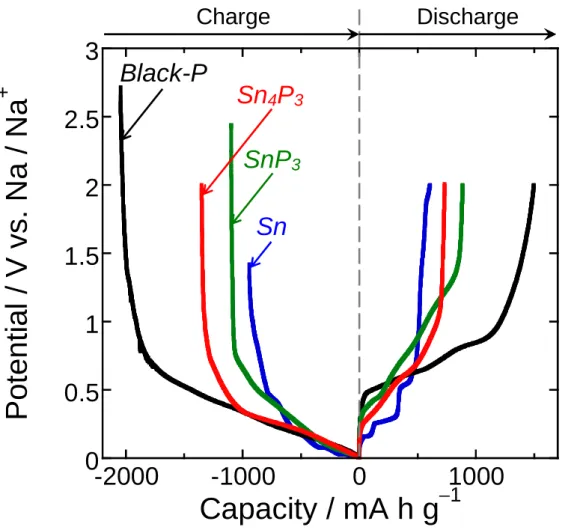
Figure 1 shows the galvanostatic charge (sodiation) and discharge (desodiation) potential profiles of
the Sn4P3 and SnP3 electrodes in the conventional organic electrolyte (NaTFSA/PC) at the first cycles.
For comparison, the figure shows the results for the electrodes of black-P and Sn. The initial discharge
capacity was increased with increasing the composition ratio of P in the active materials. The Sn4P3 and
SnP3 electrodes exhibited initial capacities larger than 250–300 mA h g–1, typical capacities obtained for
hard carbon-based electrodes.1 Potential shoulders at 0.2–0.5 V and 0.5–1.2 V in the discharge profiles
probably originate from desodiation reactions of Na–Sn and Na–P phases, respectively. It is suggested
that the tin phosphides underwent a phase separation into Sn and P in the charge reaction at the first
cycle.
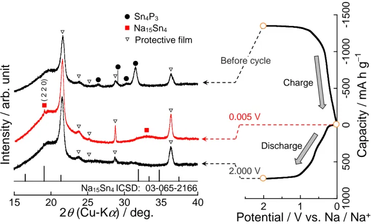
To elucidate the mechanism, we performed ex-situ XRD measurement for the Sn4P3 electrode during
the first charge−discharge reactions (Fig. 2). Sharp peaks at 21.6° and 31.5° were caused by an organic
protective film covering the electrode surface. In the charge process, the diffraction peaks of Sn4P3
disappeared. New diffraction peaks, appeared at around 19.0° and 33.0°, can be possibly attributed to
state at 2.0 V, we did not observed Sn4P3, Sn, and P, indicating the amorphization of Sn and P.
According to the reaction mechanism reported by Yang et al.,4 we consider that the Sn4P3 electrode
probably showed charge−discharge reactions described as following equations:
(Sodiation at the first cycle) Sn4P3 + 24Na+ + 24e− → Na15Sn4 + 3Na3P (1)
(Sodiation/desodiation at the subsequent cycles) Na15Sn4 ⇄ 4Sn + 15Na+ + 15e− (2)
Na3P ⇄ P + 3Na+ + 3e− (3)
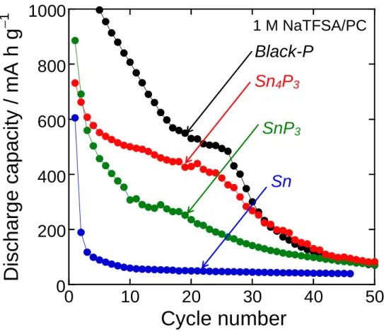
Figure 3 represents cycling performances of the Sn4P3 and SnP3 electrodes as compared with those of
electrodes using Sn alone and P alone. The discharge capacity of the Sn electrode rapidly decreased by
the initial five cycles. This poor cyclability originates from the volume expansion during sodiation, the
aggregation during desodiation, and the resulting deterioration of active material layer.5 In contrast, the Sn4P3 and SnP3 electrodes showed an improved cyclability. In particular, the Sn4P3 electrode exhibited a
better performance: the capacities over 400 mA h g–1 was maintained until the 25th cycle. The reason for the improved cyclability is probably the complementary effects of Na-storage reactions of Sn and P in
the Sn−P alloys.4-6 Na15Sn4 alloy acts as a conducting pathway to activate the reversible Na storage
reaction of nonconductive Na3P particles. In addition, the well-dispersed Na3P phase provides a shielding
matrix to prevent the aggregation of Sn. Nevertheless, a capacity decay was observed after the 26th cycle,
which is similar to that of the P electrode. These results were presumably caused by large volumetric
changes of P during sodiation and desodiation.
For a silicon anode for LIB having a high theoretical capacity and large volumetric changes during
charge/discharge, we have revealed that some ionic liquid electrolytes are very effective to improve its
anode performance.10-12 In a conventional organic electrolyte, a thick surface layer with inhomogeneous
thickness was formed on the electrode. This leads to intensive Li-insertion/extraction reactions on
specific regions coated with thinner layer and an accelerated deterioration of Si active material layer.12
On the other hand, the intensive reactions and the deterioration were effectively suppressed in an ionic
stability.12 Expecting similar improvement in the performance, we applied two kinds of ionic liquid
electrolytes to the Sn4P3 electrode.
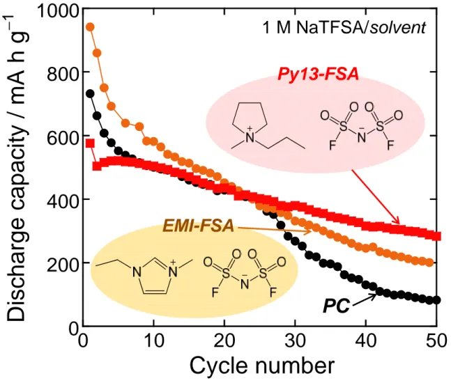
Figure 4 shows dependence of discharge capacities on cycle numbers for the Sn4P3 electrodes in ionic
liquid electrolytes using Py13-FSA and EMI-FSA. The capacity fading was relatively suppressed by
using EMI-FSA. In case of Py13-FSA, the cyclability was further improved: the capacity of 280 mA h
g−1 was attained at the 50th cycle. As the authors expected, the ionic liquid electrolytes probably formed thin and uniform surface layers. This consideration is supported by higher initial Coulombic efficiencies
of the ionic liquids (Py13-FSA: 78%, EMI-FSA: 75%) compared with the organic electrolyte (PC: 54%).
With respect to EMI-FSA, it is suggested that the cathodic decomposition of EMI cation occurs by an
initial attack on an acidic proton attached to the ring carbon between two nitrogen, which leads to a
successive alkylation of the ring even after the second cycle and the resulting performance degradation.
The superiority of Py13-based electrolyte to EMI-based electrolyte has been confirmed for Si-based LIB
anodes.11,14 In addition to this, Nohira and Hagiwara et al. have reported that Py13-FSA is useful for
NaCrO2 cathode.15 These results indicate that Py13-FSA can improve the performance because it
probably forms thin and uniform surface layer to allow uniform sodiation/desodiation reactions on the
electrode.
4. Conclusion
We prepared the Sn4P3 and SnP3 electrodes by using the MA method and the following GD method,
and investigated their Na-insertion/extraction properties as NIB anodes. These electrodes showed larger
initial reversible capacities in the conventional organic electrolyte than the capacity of 250–300 mA h g–1
obtained for hard carbon-based electrodes. The formation of Na15Sn4 phase was suggested for the
sodiation state of the Sn4P3 electrode. The Sn4P3 and SnP3 electrodes showed better cycling performances
compared with the electrode of Sn alone. The improvements in the performances are probably attributed
reactions of Sn and P: Na15Sn4 alloy acts as a conducting pathway to activate the reversible sodiation of
nonconductive Na3P particles, while the well-dispersed Na3P phase provides a shield matrix preventing
Sn aggregation. The performance of the Sn4P3 electrode was further improved by using the ionic liquid
electrolytes because of the uniformly formed surface layer and the resulting uniform
sodiation/desodiation reactions on the electrode.
Acknowledgments
This work has been partially supported by Japan Society for the Promotion of Science (JSPS)
KAKENHI, Grant-in-Aid for Scientific Research (B) (Grant Number 24350094) and Grant-in-Aid for
References
1. S. Komaba, W. Murata, T. Ishikawa, N. Yabuuchi, T. Ozeki, T. Nakayama, A. Ogata, K. Gotoh, and
K. Fujiwara, Adv. Funct. Mater., 21, 3859 (2011).
2. N. Yabuuchi, Y. Matsuura, T. Ishikawa, S. Kuze, J.-Y. Son, Y.-T. Cui, H. Oji, and S. Komaba,
ChemElectroChem, 1, 580 (2014).
3. S. Komaba, Y. Matsuura, T. Ishikawa, N. Yabuuchi, W. Murata, and S. Kuze, Electrochem.
Commun., 21, 65 (2012).
4. J. Qian, Y. Xiong, Y. Cao, X. Ai, and H. Yang, Nano Lett., 14, 1865 (2014).
5. Y. Kim, Y. Kim, A. Choi, S. Woo, D. Mok, N.-S. Choi, Y. S. Jung, J. H. Ryu, S. M. Oh, and K. T.
Lee, Adv. Mater., 26, 4139 (2014).
6. J. Y. Jang, Y. Lee, Y. Kim, J. Lee, S.-M. Lee, K. T. Lee, and N.-S. Choi, J. Mater. Chem. A, 3, 8332
(2015).
7. M. Shimizu, H. Usui, and H. Sakaguchi, J. Power Sources, 248, 378 (2014).
8. M. Shimizu, H. Usui, K. Fujiwara, K. Yamane, and H. Sakaguchi, J. Alloys Compd., 640, 440
(2015).
9. H. Usui, S. Yoshioka, K. Wasada, M. Shimizu, and H. Sakaguchi, ACS Appl. Mater. Interfaces, 7,
6567 (2015)
10. H. Usui, Y. Yamamoto, K. Yoshiyama, T. Itoh, and H. Sakaguchi, J. Power Sources, 196, 3911
(2011).
11. H. Usui, T. Masuda, and H. Sakaguchi, Chem. Lett., 41, 521 (2012).
13. H. Sakaguchi, T. Toda, Y. Nagao, and T. Esaka, Electrochem. Solid-State Lett., 10, J146 (2007).
14. H. Usui, M. Shimizu, and H. Sakaguchi, J. Power Sources, 235, 29 (2013).
15. C. Ding, T. Nohira, R. Hagiwara, K. Matsumoto, Y. Okamoto, A. Fukunaga, S. Sakai, K. Nitta, S.