A study on branched fiber network
sensing utilizing Brillouin scattering
and its application to the remote testing
of telecommunication equipment
September 2017,
Chihiro Kito
Shimane University
i
Contents
1 Introduction
1.1 Background………...1
1.1.1 Structural health monitoring………..……….…...1
1.1.2 Remote monitoring of optical access network………..…3
1.2 Objective……….……5
1.3 Outline……….…...8
2 End-reflection assisted Brillouin sensing in branched network 2.1 Introduction………..…11
2.2 Basis of Brillouin optical time domain analysis (BOTDA) …..….………..13
2.2.1 Brillouin sensing mechanism………..…..13
2.2.2 Minimum detectable BFS change and spatial resolution………...15
2.2.3 System setup for Brillouin optical time domain analysis………...16
2.3 Basis of end-reflection assisted Brillouin analysis (ERA-BA) …...18
2.3.1 Principle……….…...18
2.3.2 Application to remote monitoring of optical access network…....20
2.4 Conclusion………...…...22
3 Robust and highly sensitive Brillouin sensor employing branched fiber topology 3.1 Introduction………...………...23
3.2 Branched fiber sensing with time division multiplexing probe pulse train……….26
ii
3.3 Experiment...29
3.4 Discussion...34
3.5 Conclusion...42
4 Applicability of end-reflection assisted Brillouin analysis in field 4.1 Introduction...43
4.2 Issues when deploying ERA-BA in the field...45
4.2.1 Variation in Brillouin frequency shift in installed optical fibers...45
4.2.2 Brillouin frequency shift averaging (FSAV) ...47
4.2.3 ERA-BA for broken PON monitoring...48
4.3 Pre-inquiries on installed PONs...49
4.3.1 Typical PON configuration in Japan...49
4.3.2 Branch length statistics in installed PON...51
4.3.3 Return loss of broken fiber edge...53
4.3.4 Applicable range with low end reflectance...54
4.4 Field test and experimental demonstration...56
4.4.1 Equipment setup...56
4.4.2 BFS variation measurement of deployed PONs...58
4.4.3 Loss distribution measurement of deployed PON branches...60
4.5 Demonstration of broken fiber monitoring in PON...62
iii 5 BOTDA with frequency-swept pulse
for vibration measurement and simplified setup
5.1 Introduction...67
5.2 Frequency-swept pulse BOTDA...69
5.2.1 Acoustic wave generation with frequency-swept pulses...70
5.2.2 CBG given by acoustic waves...72
5.2.3 BFS acquisition with CBG...75
5.2.4 Spatial resolution...77
5.2.5 Effective sampling rate...78
5.3 Experimental setup...79
5.4 Experimental demonstrations...81
5.4.1 Configuration of fiber under test...81
5.4.2 Experimental results...82
5.5 Conclusion...91
6 Summaries and conclusions...93
Acknowledgements...97
References...98
1
1 Introduction
1.1
Background
1.1.1 Structural health monitoring
Many of the social infrastructures such as bridges and tunnels constructed during the period of high economic growth in Japan are about to reach the end of their useful lives, and the importance of inspecting those old infrastructures is increasing. Meanwhile, there has also been a serious reduction in the labor force responsible for inspection work. The development of structural health monitoring (SHM) technology to realize the efficient inspection of these social infrastructures has been long expected.
In terms of SHM, research on optical sensing technology capable of collecting monitoring information remotely has been actively pursued [1-1, 1-2, 1-3]. An optical measurement technique utilizing stimulated Brillouin scattering, which is one of the nonlinear phenomena in optical fibers, allows the highly sensitive measurement of temperature or strain changes in a fiber under test (FUT) affixed to a sensed object [1-4]. The approach is therefore attracting attention as a promising candidate for SHM. With respect to Brillouin optical time domain analysis (BOTDA), which is a representative distributed measurement technique utilizing Brillouin scattering, various aspects of measurement performance such as spatial resolution [1-5, 1-6], measurement accuracy [1-7], sensitivity, and measured distance [1-8] have been improved in previous studies.
However, with BOTDA, it is essential to affix an FUT to a sensed object with a unicursal topology, so the wiring scalability is very poor, and the monitoring system cannot work when the affixed optical fiber is suffering from any type of optical failure
2
at a time of emergency. The sensing optical fiber should be wired flexibly and effectively according to the shape of the sensed object, and continuous long-term operation is strongly required even under harsh environments, including during an emergency. Therefore, it is necessary to improve the wiring scalability and reliability of optical sensing systems utilizing Brillouin scattering. Reducing the initial cost is also an important issue in terms of promoting SHM technology. Optical sensing technology utilizing Brillouin scattering such as BOTDA requires precise frequency control, and so it has been difficult to simplify the system configuration. However, by simplifying the system, we can expect to reduce the initial cost. Furthermore, if it were possible to capture the dynamic change in strain caused by the vibration of the optical fiber, the sensing application would be expanded, because a natural vibration mode measurement is useful for directly diagnosing structural deterioration [1-9].
3
1.1.2 Remote monitoring of optical access network
In Japan, the construction of the optical communication infrastructure is almost complete, and the quality with which large-scale facilities are maintained is very important to telecommunication carriers. Furthermore, as the facility maintenance labor force will decrease in the telecommunications industry in the near future, it is an urgent matter to develop remote testing technology that can determine a facility’s status from a central office in real time. With the development of remote testing technology, we can expect the efficiency of maintenance operations to be improved, for example onsite operation will be reduced.
Optical time domain reflectometry (OTDR) has already been put into practical use as a remote testing technology. However, when an optical splitter is installed in an access network, since the backscattered signals from the branched fibers below the splitter overlap at the trunk fiber, it is difficult to locate the fault in the fiber from the central office with OTDR. And so, the reduction in maintenance operations realized by using OTDR remote testing has remained limited. On the other hand, most of the widely used fiber-to-the-home (FTTH) optical networks employ passive optical networks (PON) with an outdoor splitter. Therefore, remote testing technology beyond the splitter has been strongly requested by the telecommunication industry. Various schemes have been proposed [1-10, 1-11, 1-12, 1-13] for realizing the remote testing of branched fibers, but reference data are needed [1-10, 1-11], or it is necessary to insert additional items with different frequency characteristics into the branches in the existing optical access network [1-12, 1-13]. This issue prevents the techniques from being introduced in actual networks.
4
In recent years, a novel technique has been proposed to overcome the issue called end-reflection assisted Brillouin analysis (ERA-BA) [1-14, 1-15], which can measure the optical properties of branched fibers individually from a central office. This is loss measurement technology that can be introduced directly into existing optical access networks without any additional components. The ERA-BA is a method using Brillouin gain analysis that is undertaken by employing a collision between a reflected probe pulse from the far end of a branch and a pump pulse. Before this approach can put to practical use, its performance in the field should be clarified by testing it using a constructed access network as a test bed. In addition, we must consider the applicability to various fault scenarios such as faults caused by broken fibers.
5
1.2
Objective
The purpose of this thesis is to improve the wiring scalability and reliability of optical fiber sensing technology by making it compatible with a branched topology. Furthermore, we apply the basic principle to communication networks and clarify the performance as the PON branch remote testing.
In general, optical fiber sensing technology makes it possible to measure changes in various parameters under harsh environments by taking advantage of the characteristics of optical fibers, namely resistance to weather, extreme heat and explosions, flexibility, and non-inductivity to electromagnetic noise. As mentioned in Section 1.1.1, Brillouin fiber sensing technology measures changes in the temperature or strain of an FUT by attaching it to a sensed object with a unicursal topology. In other words, there is a dilemma resulting from the fact that the sensing function is immediately lost when the attached optical fiber is broken by a large parameter change while emergency monitoring is underway in a harsh environment. Furthermore, since the sensing system only allows a unicursal topology, it has poor expandability. Once the optical fiber is attached to a sensed object, it requires considerable operational cost to expand wiring routes or make trivial changes.
This thesis first describes a distributed optical sensing technique for a branched topology designed to improve the wiring scalability and reliability of optical sensing systems. By undertaking sensing on a branched sensing network, unlike with a unicursal topology, even if a single branch is broken, monitoring can continue by using other branches. Furthermore, by adding optical splitters to the network, it is possible to extend the sensing area easily at any time.
6
However, if a branched optical network is adopted for the sensing topology, there is concern that the sensitivity will decrease due to an additional branching loss. In this thesis, in addition to dealing with a branched optical network, I propose a method that employs a time division multiplexed test pulse to increase sensitivity. And then, I clarify the figure of merit (FoM) of the proposed method for a traditional BOTDA. By showing the superior sensitivity of the proposed method compared with BOTDA in cases with practical system parameters (number of branches and measurement distance), I prove the wide applicability of the branched fiber sensing technique with highly robustness and easy expandability.
The optical sensing technology for the branched topology mentioned above is technically based on end-reflection assisted Brillouin analysis (ERA-BA), which is proposed as a technique for measuring the individual properties of branched optical fibers. If ERA-BA can be put to practical use as a method for testing PONs remotely, telecommunication carriers will be able to determine the state of all their communication media including the branches in real time. Thanks to the fact that all testing is accomplished remotely, the number of on-site maintenance operations can be greatly reduced. In this thesis, I describe a PON monitoring field trial with ERA-BA, and confirm the basic operation in an actual installation environment. In addition, I accumulate statistical data regarding branch length in the field to make it possible to set the target performance of the spatial and branch identification resolution of the practical system. I also clarify the applicability of ERA-BA to a fiber broken fault, which is a major factor in optical communication failure.
Various optical measurement technologies using Brillouin scattering have been proposed [1-17], but practical use cases have not progressed other than in specific
7
industries such as plant field introducing temperature or strain monitoring. To spread the use of an optical measurement system using Brillouin scattering as SHM technology, it is essential that we greatly reduce the cost of the sensing equipment. Moreover, if it were also possible to measure the natural vibration mode, which directly reflects structural deterioration, the applications would be greatly extended to various industries with a potential need for SHM technology. In this thesis, my aim is to diversify the optical sensing applications by establishing a vibration sensing technique utilizing stimulated Brillouin scattering with a simplified system setup.
As mentioned in the above three paragraphs, this thesis focuses on the following three points.
(A) A novel optical fiber sensing technology supporting branched fiber topology designed to improve the reliability and wiring scalability of sensing systems
(B) An ERA-BA field trial designed to evaluate the practicality of the remote testing of PON branches and its applicability to fiber broken fault
(C) A vibration measurement technique with a simplified system setup designed to spread the use of Brillouin sensing technology
Thus, this thesis contributes to the development of optical fiber sensing technology utilizing Brillouin scattering and its application to remote testing in the telecommunication industry.
8
1.3
Outline
As shown in Figure 1-1, this thesis has 6 chapters. Each chapter is summarized below.
The first chapter is an introduction that provides the research background, objectives, and outline of this thesis.
Chapter 2 describes the principle of ERA-BA, which is a recently proposed method supporting branched fiber topology with Brillouin gain analysis. The main body of this thesis develops a measurement method supporting a branched topology based on ERA-BA designed to establish highly reliable fiber sensing and useful remote testing of optical communication networks.
Chapter 3 proposes a branched optical fiber sensing technique based on ERA-BA using time division multiplexed probe pulses, mainly for temperature/strain measurement. With optical sensing technology corresponding to a branched optical network, reliability and wiring scalability can be greatly enhanced for a conventional unicursal topology system. In addition, from the viewpoint of sensitivity, the proposed branched fiber sensing technique is compared with conventional BOTDA. As a result, the proposed technique shows excellent sensitivity with most practical system parameters (number of branches and distance range) despite the additional branched optical loss. This is the most important result of this thesis.
In chapter 4, I apply ERA-BA as a remote testing technique for optical access networks as described in chapter 2. A prototype of ERA-BA system is designed for a field trial, and its basic function is confirmed in the field. Since information such as the branch length distribution and the dispersion of the Brillouin gain spectrum are needed
9
to define the target performance of the equipment, these statistical data are obtained by performing a sampling survey with in-service PONs. Furthermore, field trial results are described in which the individual branch loss distribution of the installed PON was measured for the first time using the ERA-BA prototype equipment. There are also many cases of fiber breakage causing optical communication failure. Since the proposed principle is strongly related to the return loss of the far end, the measurement sensitivity varies depending on the broken state of the fiber. I investigate the return loss probability when the optical cable is broken, and also report a branched fiber loss measurement obtained with a broken fiber edge.
In Chapter 5, I propose a novel method that both simplifies the sensing system configuration and increases the measurement speed of Brillouin sensing technology, including ERA-BA. With the proposed method, by using a frequency-swept test pulse for BOTDA, a convex Brillouin gain implying a Brillouin frequency shift (BFS) is observed on a probe pulse in the time domain. The principle behind the frequency-swept test pulse is that it quickly acquires BFS and has a simplified system configuration without precise frequency control. As a result, we can expect the method to be applied to the dynamic strain monitoring of structures, such as the measurement of the natural vibration mode.
Chapter 6 provides the conclusion to this thesis by summarizing the main results obtained in this work.
In conclusion, this thesis contributes to the development of SHM technology with excellent reliability and wiring scalability, and constitutes a step towards the practical use of remote testing for existing PONs with branch topology, thus contributing to maintenance efficiency. Furthermore, it can be expected to expand the applicable field
10
of the optical fiber sensing by proposing a novel Brillouin sensing method that supports vibration sensing and reduces the equipment cost of a measurement system utilizing stimulated Brillouin scattering.
11
2 End-reflection assisted Brillouin sensing in
branched network
2.1
Introduction
Optical fiber sensing technology utilizing Brillouin scattering can measure changes in temperature or strain with high sensitivity by using the dependence of those parameters on the Brillouin frequency shift (BFS). Various methods have been proposed that can measure changes in Brillouin scattering with the aim of using them to monitor the health of social infrastructures such as dams, tunnels, bridges and high-rise buildings [2-1]. Brillouin optical time domain analysis (BOTDA), which is a typical such technique, was proposed in 1989 [2-2]. Subsequently, all aspects of measurement performance including spatial resolution [2-3, 2-4], measurement accuracy [2-5], sensitivity, and measurement distance [2-6], have been actively studied and the approach has been widely recognized as a distributed sensing technique for temperature and strain change. On the other hand, BOTDA was originally developed as a nondestructive technique for measuring optical fiber loss by measuring the Brillouin gain intensity [2-7].
End-reflection assisted Brillouin analysis (ERA-BA) has recently been proposed [2-8, 2-9], which can measure the individual characteristics of branched fibers based on BOTDA. ERA-BA measures the branched fiber characteristics by analyzing the Brillouin gain caused by a collision between a pump pulse and a probe pulse reflected from the far end of the branch. The branched fiber measurement technique with
12
ERA-BA enables the remote testing of all optical access networks that include branched fibers, and greatly reduces the number of on-site operations. It can be expected to provide the high quality maintenance of extremely large network facilities at a low cost and with a small labor force.
In this thesis, I study optical fiber sensing technology that provides high reliability and wiring scalability corresponding to a branched network based on ERA-BA. I also study the practicality of ERA-BA as a remote testing method for telecommunication networks with a splitter, i.e. passive optical networks (PONs), in an actual installed environment.
This chapter outlines the basic techniques used in this work, namely BOTDA and ERA-BA. Section 2.2 describes the basic principle of BOTDA. Section 2.3.1 describes the principle and applicable conditions for ERA-BA. Furthermore, section 2.3.2 describes the expected impact of introducing the remote testing of PON branches using the conventional telecommunication facility maintenance scheme as an example.
13
2.2
Basis of Brillouin optical time domain analysis (BOTDA)
2.2.1 Brillouin sensing mechanism
The optical measurement technique utilizing Brillouin scattering is a method that employs the linear dependence of the Brillouin frequency shift (BFS) on temperature or strain change. To determine the BFS, the peak frequency of the Brillouin gain spectrum (BGS) is observed with a fitting function. Brillouin scattering is the inelastic scattering of photons by acoustic phonons, and Brillouin scattering downshifts light frequency as shown by Eq. 2-2-1. 2nvA B u λ n = (2-2-1)
Here, nB is the BFS, n is the refractive index of the medium, vA is the sound velocity,
and λu is the wavelength of the pump light. For a silica optical fiber (refractive index n:
1.45), with a sound velocity vA of 5.96 km/s, the frequency shift caused by Brillouin
scattering in the 1.55 µm wavelength band is approximately 11.1 GHz [2-10].
Brillouin sensing techniques monitor the linear increase in BFS that occurs with increases in temperature [2-11] or tensile strain [2-12]. This dependence is due to the fact that the sound velocity in the optical fiber varies depending on temperature and strain. Equations 2-2-2 and 2-2-3 express the dependence of BFS on temperature and tensile strain, respectively.
( )
( )
tr[
1(
)
]
B t =nB +Ct t−tr n (2-2-2)( )
( )
0[
1]
B ε n ε n = B +Cs (2-2-3)Here, t is the temperature, tr is the reference temperature, and ε is the tensile strain. Ct
14
0.0483 MHz/µε, respectively, at a wavelength of 1553.8 nm [2-13]. With Brillouin sensing technology, since the temperature and strain changes cannot be measured separately, the BFS change δnB is sometimes expressed as Eq. 2-2-4.
( )
ε δ δεδnB t, =Ct t+Cε (2-2-4)
Here, δt and δε are changes in temperature and strain, respectively. In practice, to compensate for changes in temperature or strain not intended for measurement, a reference optical fiber or reference data are prepared.
15
2.2.2 Minimum detectable BFS change and spatial resolution
In general, fitting is applied to the obtained BGS to determine the BFS. The BGS has a shape that can be approximated by the Lorentz function with the center frequency at nB and a full width at half maximum of ∆nB. When quadrature fitting is applied to the
full width at half maximum of the BGS, the measurement error of the BFS, namely the minimum sensitivity of the BFS change, can be estimated with Eq. 2-2-5 [2-14].
( )
( )
B z SNR z δ n σn = ⋅∆ 4 3 1 (2-2-5)Here, SNR(z) is the signal-to-noise ratio (SNR) of the BGS peak at position z, and δ is the frequency sample step (δ << ∆nB). Eq. 2-2-5 shows that the detectable minimum
BFS change decreases in inverse proportion to the SNR of the measured BGS distribution, and increases in proportion to the square root of the frequency sample step δ.
Brillouin optical time domain analysis (BOTDA) measures the Brillouin scattering intensity as a function of time. When the response speed of the photo receiver is sufficiently high, the spatial resolution corresponds to the pulse width of the pump light. The spatial resolution δz is expressed by Eq. 2-2-6 [2-15].
2 u
vW z =
δ (2-2-4)
Here, v is the group velocity of light in the optical fiber, and Wu is the pulse width of the
pump light. The spatial resolution of the standard BOTDA is limited to 1 m. This is because the phonon lifetime is about 10 ns and it is difficult to realize a pump pulse width of less than 1 m.
16
2.2.3 System setup for Brillouin optical time domain analysis
To measure the BFS along a sensing fiber, it is necessary to obtain the BGS distribution as the frequency dependence of the Brillouin gain intensity. Figure 1 shows a conventional BOTDA system. Generally, the pump light is pulsed light, and the probe light is launched from the opposite side by using a continuous beam. And Brillouin interaction occurs during the collision of the test beams in the fiber under test (FUT). The laser output is divided by a coupler to form a pump light and a probe light. To generate a Brillouin interaction between the test beams, the probe light frequency is downshifted with an optical frequency shifter by the BFS (approximately 11 GHz at a 1.55 µm wavelength). The pump light is pulsed by a pulse shaper such as an electro-optic modulator, an acousto-optic modulator, or a semiconductor optical amplifier. To eliminate the polarization dependence of the Brillouin gain, a polarization scrambler or polarization switch is inserted in the optical path of the pump or probe light. While sequentially changing the frequency offset by using the frequency shifter, it scans in the vicinity of the BFS of the FUT. The Rayleigh scattering of the pump light, which is an unnecessary signal component, can be eliminated with a narrow linewidth optical filter such as a fiber Bragg grating (FBG). The Brillouin gain spectrum distribution can be obtained with the above measurement system.
17
18
2.3
Basis of end-reflection assisted Brillouin analysis (ERA-BA)
This section outlines the principle of ERA-BA. ERA-BA is a unique measurement technique that is compatible with branched fiber topology. In other words, it is possible to measure the characteristics of the optical fiber for each branch connected to the optical splitter by using Brillouin gain analysis. In this thesis, by further developing ERA-BA, I aim to realize a highly robust branched fiber sensing and remote testing technology for PON branches.
2.3.1 Principle
Figure 2 is a schematic illustration showing the principle of ERA-BA. ERA-BA is an optical measurement technique that measures the characteristics of each branched fiber from the trunk fiber side. Here, the characteristics are the optical loss, and changes in temperature and strain. The branched fiber characteristics are measured by Brillouin gain analysis by employing the collision between the pump pulse and the probe pulse returning from the far end of the branch. The dependence of the Brillouin gain intensity on the pump power is useful for measuring branch loss. Meanwhile, the BFS, which varies depending on changes in temperature and strain, is measured for optical fiber sensing with branched fiber topology.
To cause the test pulses to collide in the branched fibers, we need an optical filter that reflects the probe pulse at the far end of the branched fiber. The pump pulse is launched after the probe pulse with a time delay of ∆t to collide at a position v∆t/2 from the far end. A distribution measurement is possible by sequentially changing the time delay ∆t. To generate far-end reflection effectively in an existing access network, we
19
can use a test light cut-off filter as recommended in ITU-T L.66 [2-16]. On the other hand, with branched fiber sensing, we can use an FBG filter or a total reflection filter designed for the probe wavelength.
The round trip time difference of the returned probe pulses caused by the different lengths of the branched fibers is used to determine the signals from a branched fiber. To identify the branched fibers, we at least need the branch length difference δL expressed by Eq. 2-3-1. This is called the branch identification resolution.
2 r
vW L =
δ (2-2-4)
Wr is the probe pulse width. For telecommunication networks, since the branched fiber
lengths differ randomly by several meters, the target performance of the fiber identification resolution should be equal to or higher than that value. Statistical data for branch length difference collected in the field are shown in Section 4. With branched fiber sensing, the branch length difference can be arbitrarily set by using an extra delay fiber. Note that the spatial resolution can be defined by Eq. 2-2-4 using the pump pulse width as with conventional BOTDA.
20
2.3.2 Application to remote monitoring of optical access network
When ERA-BA is developed as a loss distribution measurement technique for use with a branched optical fiber, it is expected that it will be widely used as a remote testing technology for PON branches in the telecommunication industry. This section explains the changes made to the maintenance scheme when a PON monitoring technique such as ERA-BA is put into practical use.
In general maintenance operation schemes, optical faults in access networks are often detected thanks to a user's failure report. When a failure is suspected in an optical fiber, a trunk cable loss measurement is undertaken from a central office using optical time domain reflectometry (OTDR) to first isolate the failure location. If an irregular loss is found on the trunk cable, the maintenance operator travels directly to repair the failure. On the other hand, if the soundness of the trunk optical cable is guaranteed by the OTDR test, a branched fiber fault will be strongly suspected. Since it is difficult to determine the state of the system beyond the optical splitter from the office, operators travel to the user’s premises, and an OTDR test is performed from the optical network unit (ONU) side to identify the fault location on the branched fiber [2-17]. In the present scheme, there is a problem in that fault location and recovery work on the branched fiber is influenced by the user's home situation, and it is impossible to realize efficient maintenance led by the communication carrier.
If we can realize the remote testing of branched fibers, it will be possible to confirm the soundness of all the optical communication media including beyond the splitter from the central office. In other words, there is no need to disturb the user at home at the time of a fiber failure because the communication carriers can understand the condition
21
of the facilities and determine a maintenance schedule. In addition, when the soundness of the trunk and branched fiber is guaranteed, an ONU failure can be strongly suspected, so the maintenance operation can be completed simply by mailing an ONU to the user reporting the failure. Furthermore, by conducting periodic testing of the entire optical access network using the PON branch monitoring technique, there is the possibility that age related deterioration in fiber loss can be detected. As a result, a facility renewal and maintenance operation can be carried out systematically before the communication link fails. As described above, the maintenance operation cost for a huge number of network facilities would be greatly reduced by enabling the remote testing of branched fiber.
22
2.4
Conclusion
Chapter 2 outlined BOTDA, which is a representative optical measurement technology utilizing Brillouin gain analysis. This thesis describes an optical fiber sensing technology that uses Brillouin scattering, which can measure temperature and strain changes with high sensitivity, from the viewpoint of its compatibility with branch topology, the simplification of the system configuration, and dynamic strain measurement. In addition, the basic principle of ERA-BA as the technical basis of this thesis was described in this chapter. ERA-BA is a distributed measurement technology that can be employed with branched fiber topology. I described the efficient maintenance scheme that is realized when ERA-BA is put to practical use for remote PON branch monitoring in the telecommunications industry. In chapter 3 and subsequent chapters I discussed an investigation designed to realize optical sensing technology for use with a branched fiber topology and the remote testing of PONs by further developing ERA-BA.
23
3 Robust and highly sensitive Brillouin sensor
employing branched fiber topology
3.1
Introduction
The distributional analysis of stimulated Brillouin scattering has been widely investigated by using time domain [3-1]-[3-3] and correlation domain analysis [3-4] with a view to observing strain and/or temperature variations induced in optical fibers. Conventionally, in such technologies, sensing points are unicursally connected with a single optical fiber, even when the sensed area extends in two or three dimensions (Fig. 3-1(a)). With the conventional sensing fiber topology, it is difficult to expand the sensed area flexibly. Moreover, a single fiber fault causes the entire sensing system to shut down. To overcome this problem, a branched fiber configuration with a passive power splitter was proposed to improve network reliability and provide configuration flexibility [3-5]. However, the approach involved allocating different Brillouin frequency shifts to each branch by changing such material properties of the fibers as the dopant concentration, and so standard optical fibers could not be employed. A simplified branched fiber sensing technique with one sort of branched fiber is expected to be suitable for temperature/strain sensing, e.g. in data center or civil structure monitoring, by utilizing its flexible scalability and high reliability (Fig. 3-1(b)).
Recently, a novel technology called “end-reflection assisted Brillouin analysis (ERA-BA)” was proposed, which employs a passive splitter to distribute a probe signal to branches, and distinguishes between individual branches simply by using their length
24
differences [3-6], [3-7]. With this technique, a single pair of pump and probe pulses yields a Brillouin interaction at a single point when test pulses are launched. While the technology has been presented for monitoring so called passive optical networks (PONs) deployed in optical access networks, it can be straightforwardly applied to the Brillouin sensing mentioned in the previous paragraph, without any intentional allocation of the Brillouin frequencies, yield robustness and flexibility of the system thanks to its branched fiber topology.
However, the issue of sensitivity, or dynamic or distance range of the system has not yet been addressed. Intuitively, the insertion of the passive splitter causes significant optical losses when the light goes in the both directions, so that the system should pay some penalty to achieve distance range that is equivalent to that of the conventional unicursal systems. The purpose of the last section of this chapter is to discuss the applicable range of the proposed system.
In this chapter, a novel probe signal design for end-reflection assisted Brillouin analysis was presented to enhance the energy efficiency of the measurement while still employing time domain analysis, and thus maintaining system simplicity [3-8]. After describing the principle (section II) and an experimental demonstration (section III), author compares the proposed system with a branch topology with the conventional Brillouin time domain analysis (BOTDA) system with a unicursal fiber topology, and show that a simulation implies a superior sensing signal-to-noise ratio to that of BOTDA for whole surface monitoring in spite of the disadvantage of the branched loss. Author believes the proposed branched fiber sensing technology would be particularly useful for application to a temperature and strain sensor with a very robust and flexible topology.
25
Fig. 3-1. Illustration of sensing fiber topology (a) a unicursal topology for conventional sensing technique such as BOTDA (b) a branch topology for the proposed technique.
26
3.2
Branched fiber sensing with time division multiplexing probe
pulse train
Fig. 3-2(a) shows the proposed Brillouin analysis configuration for monitoring branched optical fiber. The sensor fiber consists of a passive power splitter and N branches with end reflectors in every branch. To describe the configuration, let the lengths of the branches with respect to the shortest branch be 0<t1<t2, −−, <tN-1. And
the ti values are written in terms of the roundtrip times to the end of each branch. The
total branched sensing range is assumed to be T.
The technology proposed here uses a series of probe pulses and a single pump pulse, instead of a single pair of probe and pump pulses. The probe beam consists of a series of pulses with a pulse width of ∆tpro, a repetition interval of ∆T, and a train length that
nearly equals the entire sensing range, T. Hence, the number of launched probe pulses is about T ∆/ T. A single pump pulse with a Brillouin frequency shift (BFS) accompanies
the probe pulse train with an interval of ∆t after the last probe pulse. The probe pulses are reflected by the end reflectors in each branch, and the m-th probe pulse collides with the pump pulse and acquires the Brillouin gain at a distance of vg(∆t+m∆T)/2 from the
end reflectors in every branch, where vg is the light velocity and m is an integer
(0≤m≤T/∆T). The entire range, T, can be analyzed by scanning ∆t from 0 to ∆T (instead
of scanning the entire range, T).
To determine the Brillouin gains yielded in the branches individually, the probe pulses, which are recombined at the splitter, must not overlap each other. In other words, the probe pulses from different branches must be located in different time slots. With some length manipulation of the branches, this condition can be realized in a
27
straightforward manner as shown in Fig. 3-2(b). Set the probe pulse interval ∆T at N∆tpro. Then, the probe pulses from the i-th branch are located at m∆T+ti. The
necessary and sufficient condition for avoiding any overlapping of the probe pulses is that all of the remainders of the branch lengths, ti, when they are divided by ∆T, shall be
different from each other. This condition can be realized by manipulating the branch length, and the required manipulation range is always less than ∆T.
The described technology enhances the data collection rate, or reduces the data collection time, by a factor of ~T ∆/ T, by comparison with the previously investigated
single pair probe-pump scheme. Also, to increase the data collection rate, author proposes a fiber sensor design that employs different BFS fibers for the feeder and branched fibers. Since no Brillouin interaction occurs on the feeder fiber, the test beam repetition rate (data collection rate) is decided solely by the roundtrip time of the longest branched fiber (excluding the roundtrip time of the feeder fiber). Additionally, in terms of pump depletion, the effect does not occur in feeder fiber. To benefit from the use of different BFS fibers in the sensing fiber topology, the difference between the BFSs of the feeder and branched fibers should be designed to be sufficiently wider than the expected BFS change caused by temperature or strain.
28
Fig. 3-2. (a) Proposed Brillouin analysis configuration for monitoring branched optical fiber. (b) Length manipulation technique for identifying probe pulses from each branched fiber.
29
3.3
Experiment
The experimental system, which is shown in Fig. 3-3, is similar to that described in [3-7] except for its use of the newly designed multi-probe pulse train. The probe and pump beams were intensity modulated with acousto-optic modulators (AOMs), with the electrical pulses programmed in the manner described in section II. The frequency of the probe beam was downshifted by the Brillouin frequency shift by using a single sideband modulator (SSBM) as a frequency shifter. By changing the sinusoidal frequency fB input to the SSBM, the frequency of the probe beam was swept to observe
the Brillouin gain profiles at each point.
Fig. 3-3. Experimental setup for end-reflection assisted Brillouin gain analysis, SSBM: Single side-band modulator, AOM: Acousto-optic modulator, EDFA: Erbium doped fiber amplifier, PS: Polarization scrambler, B-PD: Balanced photo-detector, BPF: Bandpass filter, LPF: Low pass filter.
30
The branched fiber network used here is depicted in Fig. 3-4. The network included 4 branches. The fibers used for all the branches had a specified length of 1000 m (±1 m). The length of each branch was manipulated by inserting 2 m-long patch cords behind the splitter. The lengths of the branches measured by OTDR (resolution: 1 m) were 1000, 1004, 1008, and 1012 m, respectively, or in terms of delay time, there were roundtrip delay differences of 40 ns (∆tpro) between every neighboring pair, hence, the
probe pulse interval, ∆T, was designed to be 160 ns. The entire roundtrip time, T, was about 10 µs, so that the ideal T/∆T is ~62. To investigate the ability to detect temperature change, part of a specific branch (#2) was immersed in a temperature-controlled hot bath.
31
The test beam design is described in detail below. The probe and pump beams were emitted from the same semiconductor laser oscillating at 1556 nm. The probe and pump beams were carved by an acousto-optic modulator to generate 40 (~T ∆/ T) sequential
probe pulses with a width of ∆tpro = 40 ns accompanied by a single 40 ns wide pump
pulse. The actual probe pulse repetition period, ∆T, was set at 333 ns, while the strictest design can reduce ∆T to N∆tpro = 160 ns. By scanning the time interval ∆t from 0 to 333
ns, the analysis was accomplished for the entire range. By scanning the frequency shift of the probe beam, Brillouin spectra were obtained over a 160 MHz range. The incremental step of the optical frequency and the time interval were 2 MHz and 14 ns, respectively. The measurement was repeated 5000 times for a specific probe optical frequency and pump time delay to average the Brillouin gain. The peak Brillouin frequency shift at each interaction point was determined by quadratic fitting.
Fig. 3-5 shows the Brillouin spectra obtained around the hot bath in the heated branch. Spectra obtained in other branches are also shown for comparison. The variation in the Brillouin spectra around the heated point was clearly shown. In this case, the spatial resolution was determined by the pump pulse width (40 ns) at about 4 m.
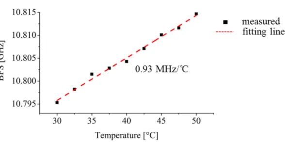
Fig. 3-6 shows the dependence of the Brillouin frequency shift observed at the hot point at the target temperature of the hot bath. It was seen that the proportional coefficient is 0.93 MHz/°C, which agreed well with the commonly accepted value for silica glasses.
32
Fig. 3-5. Measured Brillouin gain spectra distribution in branched fiber. The part of the fiber around the heat bath in #2 is shown as an enlarged figure.
Fig. 3-6. Temperature dependence of Brillouin frequency shift measured at hot bath point of branched fiber #2.
33
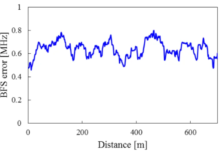
To confirm the BFS error of the above experiment, Fig. 3-7 shows the BFS error distribution after fitting by using quadratic fitting in branched fiber #1. To analyze the BFS error, the standard deviation of the BFS distribution was calculated from a set of 30 close positions. The strained region caused by bobbin winding between 700 m and 1000 m was omitted from the evaluation. The average calculated error was 0.64 MHz and it was distributed evenly in the longitudinal direction. The sensing accuracy was almost same as the recently reported value for standard BOTDA [3-9].
34
3.4
Discussion
The branch sensing topology provides a highly robust sensing network by comparison with conventional BOTDA with a unicursal topology where the entire system can easily shut down the result of a single fault on a sensing fiber. In addition, the proposed branch sensing system has the merit of flexible scalability on demand. In this section, author compares the proposed branched system and conventional BOTDA with a single unicursal fiber in terms of detection sensitivity with the same available input optical power.
Fig. 3-8 shows the two sensing systems compared here. In the proposed branched system, the number of branches, branched fiber length and branch length difference are set at N, L and ∆L/2, respectively, while conventional BOTDA uses a single fiber whose length is NL. Accordingly, the total sensing length is NL in both systems. The pulse widths of the pump and probe beams in the proposed system are set at ∆L/vg, where vg is
the group velocity of the light in the fiber. The conventional BOTDA uses a pump pulse width of ∆L/vg and a continuous probe beam. As a result, the spatial resolutions of both
systems become ∆L. The available pump power for both systems is +15 dBm at the fiber input (before the splitter in the case of ERA-BA). The probe power is selected appropriately so that the SNR is maximized at the fiber far end in both systems. This is described later. With the conditions described above, the signal-to-noise ratios (SNRs) of the two techniques were compared as a sensing performance indicator.
First, note that the time needed to perform a single measurement over the entire fiber length is almost the same in both systems. Obviously, the single measurement time in the BOTDA is ΝL/vg. The time is also ΝL/vg in the proposed system, because it
35
requires N scans of ∆t, while it accomplishes N simultaneous measurements in N branches. Therefore, when comparing the two systems, the SNR of the single measurement directly reflects the SNR obtained in the same measurement time. If author assumes that the optical receiver noise is the same in both systems, the comparison results in the magnitude of the obtained Brillouin gains in the systems.
Here, author analyze the Brillouin gain obtained at the far end of the sensing fibers (the worst SNR points) in the two systems. In both cases, the Brillouin interaction in the fiber is governed by the coupling equations below:
p p s eff B p PP P A g dz dP α − − = (3-1) s s p eff B s P P P A g dz dP = −α − (3-2)
where Pp and Ps are the pump and probe powers at the interaction point, z is the distance
along the fiber, gB is the Brillouin gain coefficient, Aeff is the effective area of the fiber
core, and α is the fiber loss coefficient. By numerically solving the equation, including the branch loss for the proposed system, the pump intensities when it interacts with the probe beam at the far end can be found. The parameters used in the simulation are as follows: gB: 5×10-11 m/W, Aeff: 5×10-11 m2, and α: 4.6×10⁻⁵ /m.
If the input probe power is increased, the increased detection power improves the SNR, while on the other hand, the increased pump depletion effect degrades it. To solve the problem of the trade-off, author numerically simulates the coupling equations for several probe beam powers and find the pump power when it interacts with the probe beam at the far end, and then analyze the obtained signal amplitude caused by the Brillouin gain. The probe power increment, ∆Ps(L), for the proposed branch sensing
36
(
L)
L L P L P NA g L P s p eff B s = ∆ −α∆ ( ) ( ) ( ) exp for ERA-BOTDA, (3-3),
(
NL)
L NL P P A g NL P s p eff B s = ∆ −α∆ ( ) (0) ( ) exp for BOTDA. (3-4)
Here Pp(z) and Ps(z) stand for the pump and probe powers, which can be calculated
numerically by solving Eq. 3-1 and Eq. 3-2 , respectively.
Fig. 3-8. The conditions for the system comparison. The sensitivity enhancement caused by the averaging effect is negligible in this comparison because the times required for monitoring the entire network are the same.
37
Examples of the results obtained for the proposed system and conventional BOTDA are shown in Fig. 3-9(a) and (b), respectively. Here, the increments of the probe power at the far end are calculated as a function of the input probe power, and normalized with respect to the maximum values for each total distance. The simulation results show that there are optimum probe powers for maximizing the signal amplitudes that consequently maximize the SNRs in both systems. By using the optimum probe power, author calculated the signal amplitudes at the far end of the fibers with a constant input pump power of +15 dBm.
Fig. 3-9. Simulation results of the optimum probe powers for maximizing the signal amplitudes at the far end, of (a) the proposed technique for 8-baranch sensing and (b) BOTDA.
38
Fig. 3-10 shows examples of the probe power increments when the total sensing lengths are 60 km for both systems. As seen in the figure, the distributions of the probe power increment are flattened by using large numbers of branches. This is because there is accumulated pump depletion in BOTDA, while the proposed branched system suffers from less pump depletion. Moreover, even at z=0, the branched system yields larger signal amplitudes. This is because we can use a stronger probe in the branched system, while in conventional BOTDA, the probe power should be suppressed to avoid the pump depletion to reach the far end. Here author focused on the minimum probe power increment in the sensing areas to ensure the worst SNR values for the entire system. The minimum increment values are given at the far ends of the fibers from the pump input ends, and are z=L for the proposed branch sensing and z=NL for BOTDA. It can be seen that, the minimum probe increments with the proposed branch sensing can be larger than those with BOTDA even though the pump powers in the proposed systems are significantly attenuated by the splitter loss.
39
Fig. 3-10. Example of simulated probe power increment (Brillouin gain) distributions for the proposed branch sensing (break lines) and the BOTDA (solid line). The total sensing lengths are 60 km. The horizontal axis shows the distance normalized by L (for the proposed branch sensing) and NL (for the BOTDA).
40
Fig. 3-11 shows simulated and experimental results for the figure of merit (FOM) of the proposed system (the relative probe power increment at the far end) with respect to conventional BOTDA, as a function of branch number. The simulation result is the ratio of Eq. 3-3 and Eq. 3-4. Various total sensing lengths from 5 km to 60 km are simulated. For the experimental result, the ratio of the Brillouin gain between the two systems is plotted as the FOM. Author found that the experimental results agree with the simulations for total sensing lengths of 40 and 60 km. Here it should be stressed that, for a wide range of the total lengths, the proposed system can outperform the conventional BOTDA if author chooses the branch number appropriately. In addition, the FOM has its peak value, so the number of branches should be chosen to maximize the system performance. For example, an improvement of about 17 dB is achieved for a total fiber length of 60 km, which seems to be very large. As described above, the improvement is mainly due to the fact that the branched distribution of the probe beam suppresses the pump depletion effect, and enables a large pump power to be used at the far end. It seems that the result is important since it reveals the useful performance of the proposed branched sensing technique for 2- or 3-dimentional sensed objects.
41
Fig. 3-11. Simulated and experimental results of the figure of merit of the proposed branch sensing for BOTDA with various total sensing lengths.
42
3.5
Conclusion
Author investigated a novel optical time domain Brillouin analysis technique, which includes branch sensor fibers that are connected by a passive power splitter, to enhance system reliability and flexibility, as well as the signal-to-noise ratio with respect to conventional BOTDA, which consists of a unicursal fiber topology. Author described a probe pulse arrangement designed to enhance the utility of the time sequence and so greatly reduce the measurement time. The technique is based on a previously proposed end-reflection assisted time-domain Brillouin analysis approach for monitoring branched fiber networks [3-6], [3-7], however, this chapter yields a novel (and author believe very important) finding, namely that the proposed system with a branch fiber network can outperform the conventional unicursal BOTDA in the signal to noise ratio, by choosing an appropriate number of branches. The simulation shows that, instead of branch loss, the avoidance of pump depletion in the branch configuration enhances the signal power at the far end of the fiber. Additionally, the branch topology increases reliability against sensing fiber faults. The branched topology would be especially useful when the sensed object occupies 2- or 3-dimensional space.
43
4 Applicability of end-reflection assisted
Brillouin analysis in field
4.1
Introduction
The number of fiber to the home (FTTH) service users has been increasing rapidly and communication carriers are making an effort to reduce the maintenance costs incurred by massive amounts of optical equipment. To provide the FTTH service, a passive optical network (PON) is commonly employed in an optical access network, in which a passive power splitter is inserted between the customer’s premises and the central office to reduce construction costs. A diagnostic issue remains in relation to the remote surveillance of PON branches. Traditional optical time domain reflectometry (OTDR) only provides a superimposed backscattering trace from all the branches, thus making it difficult to understand the fault position and loss value in a branch. As a result, the operator cannot completely ensure the health of the optical fiber without access to the customer side [4-1]-[4-3].
Recently, a novel technique was proposed for loss measurement in PONs called “end-reflection assisted Brillouin analysis (ERA-BA),” which distinguishes individual branches by using end-reflections at the terminated ends and their different branch lengths [4-4]. With this technique, loss information about individual branches is obtained by analyzing the local Brillouin gain at the position where the collision occurs between a pump pulse and probe pulses reflected from the ends of the branched fibers. Previous report has already measured a 32-branched PON in the laboratory [4-5].
44
However, the performance in the field has not yet been demonstrated. In principle, the statistical properties of the fibers deployed in PONs are the keys to designing the technique. The first property is the length of the branched fibers, which impose requirements on the measurement in terms of branch discrimination capability and spatial resolution. Another property is the Brillouin frequency shift (BFS) variation along installed fibers, which is caused by manufacturing, construction and environmental factors. It is important to investigate these statistical properties for practical applications since optical fibers have not intentionally been deployed in the field from the viewpoint of Brillouin characteristics.
In this chapter, author describes a technique for measuring the loss distribution of PON branches by employing ERA-BA in the field. The proposed technique employs the frequency shift averaging (FSAV) approach to compensate for the BFS variation in the field. Author also acquires the statistical distribution of branch length and BFS variation in deployed PONs, which is useful when considering the required specifications for practical use.
In actual PON systems, the branches are not limited to be terminated by a cut-off filter as mentioned in section 2. There are other possible fiber-end conditions such as an open connector end or a fractured end before services start or when damaged. Under these conditions, a broken fiber end or a fiber end cut with nippers reflects a probe pulse with a reflectance of ten or so decibels less than with a cut-off filter. The signal to noise ratio (SNR) of the measurement result by ERA-BA becomes worse when we use such a low reflectance fiber end. In this section, with the aim of applying ERA-BA to PON branch monitoring under any fiber end-face condition, author also clarify the potential of the method for use with the low end-reflection caused by a broken fiber end-face.
45
4.2
Issues when deploying ERA-BA in the field
4.2.1 Variation in Brillouin frequency shift in installed optical fibers
A BFS variation directly affects the loss measurement precision of ERA-BA in practical use. BFS variations are caused by the mechanical and environmental conditions of the installation or by climatic change, because the BFS is sensitive to strain and temperature [4-6], [4-7]. Figure 4-1 is a schematic illustration of possible factors causing BFS variations in the field. For example, as seen in Fig. 4-1, the temperatures differ in cable sections exposed to direct sunshine or in the shade, and also differ when the cables are installed underground, aerially, and in buildings. The residual strain applied to cabled fiber during manufacture and after construction is also a cause of BFS variation. In an earlier study [4-8], it was reported that a residual strain of less than 0.1% was distributed along cabled fiber after construction, which corresponds to a 50 MHz shift in the BFS. Figure 4-2 shows various BGSs of standardized fibers (ITU-T G.652.D [4-9] and G.657.A [4-10]), which are widely deployed in PONs. They exhibit at least a 100 MHz difference in BFS. The multiple deployments of different types of fiber and/or different manufactures are dominant factors affecting BFS variation. Therefore, a frequency range covering several hundred MHz should be compensated for in a field measurement.
46
Fig.4-1 Primary factors behind BFS variations in practical PONs.
Fig.4-3 The various BGSs of different manufacturers’ fibers and standardized classification.
47
4.2.2 Brillouin frequency shift averaging (FSAV)
A possible way to compensate for a range of BFSs in the field is the FSAV approach. In this approach, the Brillouin gain spectra (BGSs) in the expected frequency range along cabled fibers are obtained by changing the pump-probe frequency difference (Fig. 4-3 (a)). The following two methods can be considered for FSAV. One is called “peak search” and the other is called “spectral averaging.” The peak search method depicted in Fig. 4-3 (b) traces the peak gain of the obtained BGS. On the other hand, the spectral averaging method shown in Fig. 4-3 (c) calculates the average values of the Brillouin gain over the FSAV range obtained from the BGSs. The spectral averaging method in Fig. 4-3(c) results in handling smaller signal amplitudes (gains) than the peak search method.
Fig.4-3 FSAV approaches for the proposed technique to compensate for BGS variation in a practical PON system. (a) Schematic FSAV image of Brillouin analysis, (b) peak search method, and (c) spectral averaging method.
48
4.2.3 ERA-BA for broken PON monitoring
In the deployed PONs, the branches are not always terminated by a cut-off filter. There are other possible fiber-end conditions such as an open connector end or a fractured end before services start or when damaged. Thus, the ERA-BA should be examined with low end-reflectance before its practical use. All the case for branch monitoring, including broken fiber, every length must be different; otherwise same length branches cannot be identified. In other words, the test probe pulse width should be smaller than the minimum optical path difference.
Here, author focus on the influence of end reflectance on the measurement result since the probe pulse is not always reflected by a cut-off filter, when considering a branch end before service starts or when there is a breakage. The end reflectance value has a direct influence on the SNR of a measurement result because of the decrease in the detected probe pulse power. The dynamic range of the proposed method has already been described [4-11]. Here, when taking account of the end reflectance R [dB], the single way dynamic range (SWDR) is given by
[ ]
dB(
R P P P( )
N)
SWDR probe pump d 5log
3
1 + + + − +
= b (4-1)
where Pprobe [dBm] and Ppump [dBm] are the input peak powers of the probe and pump
pulses, respectively. And is the Brillouin gain factor. Pd represents the minimum
detectable power of the receiver. The last term describes the N times averaging effect. Thus, one-third of the decrease in the end reflectance contributes to a decrease in the dynamic range.
49
4.3
Pre-inquiries on installed PONs
4.3.1 Typical PON configuration in Japan
Figure 4-4 shows a typical access network configuration in Japan. With the passive double star topology, a 4-branched optical splitter is installed inside an office and an 8-branched splitter is installed in a distribution area near the customers’ premises. A test coupler is employed for in-service optical measurement just below the 4-branched splitter. A fiber Bragg grating based test beam cut-off filter [4-12] is installed just before an optical termination unit (ONU) on the customers’ premises. The filter allows the communication wavelength to pass and reflects only the maintenance wavelength with a high reflectivity, which can be used as an end reflector in the ERA-BA. The splitter is not cascaded for in-service testing from the test coupler, thus it can be considered that any differences in the round-trip time of reflected probes are given by the branch fiber lengths below the outside 8-branched splitter.
Figure 4-5 shows two types of network configuration that have been optimized for cost-effective construction in accordance with the amount of FTTH demand. As shown in Fig. 4-5(a), 8-branched splitters are installed in the center of the distribution blocks [4-13], and are used for high penetration areas such as urban areas. Only drop cable is used from the splitter at the distribution point to the customer’s premises. On the other hand, in low penetration areas (Fig. 4-5 (b)), the splitters are installed at the front edges of the distribution blocks. Distribution cable is used from the splitter to the drop point at a telegraph pole near the customer’s premises. It can be seen that the branch length tends to be longer than those in Fig. 4-5(a).
50
Fig.4-4 Typical access network configuration in Japan.
Fig.4-5 Two types of network distribution (a) splitter at drop point in center of distribution block, and (b) splitter at distribution point at the front edge of distribution block.
51
4.3.2 Branch length statistics in installed PONs
Author investigated the branch length and its length difference in field PONs providing services for detached houses in certain areas in Japan. The branch length was measured with OTDR, and obtained from the events of the splitter loss and the reflections at the cut-off filters in the OTDR trace. Author undertook the investigation from two central offices in urban and rural areas employing the network configurations shown in Fig. 4-5 (a) and (b), respectively. The spatial resolution of the OTDR was up to 30 cm.
Table 4-1 shows statistical properties of the branch length measured in the field. The branch length was widely distributed from several meters to over one kilometer. The shortest branch length was 2 m, and the mean branch lengths were hundreds of meters. Table 4-1 shows that a spatial resolution of better than 10 m is expected to be required to cover all installed PONs, while a spatial resolution of several tens of meters might be sufficient to identify more than about 90% of the branched fibers in installed PONs. Note that the pump pulse width should be designed to provide an appropriate spatial resolution since there is a trade-off between the pump pulse width and the signal-to-noise characteristics in ERA-BA [4-5], as well as other distributed measurements.
Table 4-2 shows the statistical properties of the branch length difference, which is given by the distance between two neighboring end-reflection events in the OTDR trace. The results showed that 99.8% of branched fibers can be detected by employing a probe pulse width of no less than 10 ns (i.e. a branch discrimination resolution of 1 m), which meets the theoretical limit for ERA-BA due to the acoustic rise time.
52
Table 4-1 Measured branch length results
Configuration (a) (b) Number of samples 742 1366 Cumulative probability -10m 1.6% 0.5% -20m 2.4% 1.1% -30m 5.5% 2.1% -50m 10.8% 5.1% -100m 28.6% 14.6% -200m 66.0% 38.4% -500m 90.8% 67.9% -1000m 98.4% 88.4%
Shortest branch length [m] 2.0 2.1
Mean branch length [m] 240 463
Table 4-2 Measured branch length difference results
Configuration (a) (b) Number of samples 527 1048 Cumulative probability -1 m 0.2% 0.1% -2 m 0.4% 0.7% -5 m 6.3% 3.2% -10 m 20.5% 12.3% -20 m 39.5% 26.1% -40 m 62.2% 48.1% -80 m 81.2% 67.7% -120 m 88.8% 78.1%
Shortest branch length [m] 1.0 0.5
53
4.3.3 Return loss of broken fiber edge
Author investigated the reflectance of a broken fiber end. Two damage event conditions were prepared, namely the fiber was broken by excess bending and cut by nippers. The reflectance was measured using optical continuous wave reflectometry (OCWR) [4-14]. The measurement was repeated 250 times for both conditions. Figure 4-6 shows histograms of the end reflectance of a broken fiber end caused by (a) excess bending and (b) cutting with nippers. According to these statistical distribution results, the majority of broken fiber ends to have a reflectance of -30 to -50 dB. This means that the applicability of the proposed method for monitoring the broken branch of a PON would be determined by whether or not the technique can cope with such low end reflectance.
54
4.3.4 Applicable range with low end reflectance
To clarify the potential of the proposed method, author simulated the measurement time for 8-branched model PON systems with various end reflectance values. The PON consisted of fiber with a total length of 2, 6, or 10 km including 1 km of branched fiber. Here, the optical fiber loss was set at 0.4 dB/km and the branching loss was 10.5 dB for an 8-branched splitter. And the measurement specifications were set at a fiber length identification resolution of 3 m and a fault location resolution of 15 m [4-5]. The probe and pump pulse powers were 13 and 16 dBm, respectively.
Figure 4-7 shows a simulation result. In a measurement time of 300 seconds, the proposed technique could cope with end reflectance values of up to -53, -46, and -40 dB, for 2, 6, and 10 km long fibers under test (FUT), respectively. According to Eq. 4-7, if the PON has larger loss than simulation assumption, the allowable reflectance proportionally deteriorates 3 dB when fiber loss increases 1 dB. For example, simulated 2 km fiber having 5 dB additional loss can be coped with -38 dB end reflectance (deteriorated from -53 dB).
The investigation of broken fiber end reflectance and the simulation result show that the proposed method could be used to monitor broken branches in a typical PON system with a distance of several km, using a low power retuned probe pulse yielded by a broken fiber end.
55
Fig. 4-6. Histograms of reflectance of broken fiber end (a) and cutting end (b), and measurable range in 300 seconds (Corresponds to Fig. 3).
Fig. 4-7. Simulation result of measurement time with proposed method for various end reflectance values.