IRUCAA@TDC : Cone-beam CT (CB Throne) applied to dentomaxillofacial region
10
0
0
全文
(2) 133. Bull Tokyo Dent Coll (2006) 47(3): 133–141. Clinical Report. Cone-beam CT (CB Throne®) Applied to Dentomaxillofacial Region Aya Yajima, Mika Otonari-Yamamoto, Tsukasa Sano, Yoshihiko Hayakawa, Takamichi Otonari, Koji Tanabe, Mamoru Wakoh, Shigeru Mizuta, Hakubun Yonezu*, Kanichi Nakagawa** and Yasutomo Yajima*** Department of Oral and Maxillofacial Radiology, Tokyo Dental College, 1-2-2 Masago, Mihama-ku, Chiba 261-8502, Japan * Department of Oral and Maxillofacial Surgery, Tokyo Dental College, 1-2-2 Masago, Mihama-ku, Chiba 261-8502, Japan ** Department of Endodontics, Pulp and Periapical Biology, Tokyo Dental College, 1-2-2 Masago, Mihama-ku, Chiba 261-8502, Japan *** Department of Oral and Maxillofacial Implantology, Tokyo Dental College, 1-2-2 Masago, Mihama-ku, Chiba 261-8502, Japan. Received 6 October, 2006/Accepted for publication 6 November, 2006. Abstract Cone-beam CT (CBCT) systems specifically designed for hard-tissue imaging of the maxillofacial region have recently become commercially available. The newly-developed CBCT system, CB Throne® (Hitachi Medical Corp., Tokyo), is characterized by a number of features such as low dose, sub-millimeter spatial resolution, and a small footprint. This system has been clinically applied at Chiba Hospital, Tokyo Dental College, since April 2005. This article reports the characteristics of this system, and its diagnostic power for maxillofacial lesions and the pre-operative planning dental implants. Key words:. Cone-beam CT—Anatomical depiction— Clinical cases— Dental implant planning—Maxillofacial region. Introduction Conventional CT imaging is used as a diagnostic tool not only in maxillofacial region examinations1,7), but also in the preoperative evaluation of dental implants1). Recently, this has led to the development of various image-guided applications. A conventional CT scanner acquires sliced-image data with a fan-shaped X-ray beam and rows of detectors. Contiguous cross-sectional images are recon-. structed based on numerous projection data collected by high-speed rotation, after which they are displayed three-dimensionally. This means that longitudinal spatial resolution is sometimes sacrificed5), as a result of which the details of anatomical structures in the maxillofacial region are insufficient to allow adequate visualization in some clinical cases. Recently, cone-beam CT (CBCT) systems specifically designed for hard-tissue visualization of the maxillofacial region have become. 133.
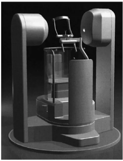
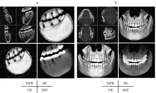
(3) 134. Yajima A et al.. clinically available2,3,6,8). The CBCT scanner can collect volume data by means of a single rotation taking between 9–40 sec due to the use of a cone-shaped X-ray beam and twodimensional detectors. Thus, CBCT systems offer three-dimensional images with high spatial resolution both longitudinally and axially through employment of an isotropic voxel matrix. This means that CBCT scanners have the potential to offer additional benefits in hard-tissue visualization of the maxillofacial region and evaluation of skeletal morphology. Earlier studies2,3,6,8) have shown that CBCT offers great advantages in comparison with conventional CT in depiction of the maxillofacial region, in terms of accuracy, scan time reduction, dose reduction, and convertible field of view (FOV), and so on. However, at the moment such systems also suffer from the disadvantages of being relatively expensive and unreliable in demonstrating soft tissue abnormalities. In this article, we provide an overview of a newly-developed CBCT system, the CB Throne® (Hitachi Medical Corp., Tokyo, Japan) (Fig. 1), and its capabilities in terms of anatomical depictions and representation of maxillofacial lesions. Moreover, we also discuss its clinical validity as a tool for the preoperative evaluation of dental implants.. Fig. 1 CB Throne®. setting. The CB Throne® is the second CBCT unit, and follows the CB MercuRay®, which was developed by Hitachi Medical Corporation3,4). The rotational arm of the CB Throne®, which consists of an X-ray tube and a reciprocating detector, is located under the patient’s chair so that the patient does not have the sensation of pressure that is generated by the around-the-head-type assembly. The footprint, 6 ft⳯6 ft, is smaller than that of its predecessor.. Characteristic of CB Throne® CB Throne® Specifications There are two types of X-ray detection system4). One type, which includes the CB Throne®, uses an X-ray image intensifier (I.I.) and a charge-coupled device (CCD) as a detector2,3,6,8). An X-ray beam is converted to an optical signal by CsI crystals, and then converted to photoelectrons. Those electrons are then accelerated and converted to an optical signal, which is detected by the CCD. The other type uses a flat-panel detector (FPD) consisting of a scintillator screen and a Si-photo-sensor array4). Several systems have been developed and made commercially available2,3,6,8) since the CBCT principle4) was applied in a clinical. The tube voltage ranges from 60 to 120 kV at 20 kV intervals. The tube current is 10 or 15 mA. There are two alternatives voxel sizes and FOV combinations. One is 0.1 mm with a 2 in diameter (D-mode) (Fig. 2a), and the other is 0.2 mm with a 4 in diameter (I-mode) (Fig. 2b). The sensitive I.I. area can be set to either 4 or 7 in diameter depending on the mode selected. The scan time is 9.6 sec for a 360-degree rotation, and 288 projections are carried out. The reconstruction is processed according to the Feldkamp algorithm4), and the resultant image matrix is isotropic 512⳯ 512⳯512..
(4) 135. Clinical Application of Cone-beam CT. a. b. MPR. SR. MPR. SR. VR. MIP. VR. MIP. Fig. 2 Two alternative FOVs for selected mode, D-mode (a) and I-mode (b) Tri-axis multiplanar reconstruction (MPR), volume rendering (VR), surface rendering (SR), and maximum intensity projection (MIP) from upper left to bottom right, respectively.. axial. cross-section. panorama. Fig. 3 Dental reformatted images Corresponding cross-sectional images (upper right) and partial panoramic image (lower) are generated just after line/curve marking dental arch is defined on selected axial image and equally-spaced lines perpendicular to arch are created (upper left).. The software, CB Works, is capable of displaying variously processed images, such as Multiplanar reconstruction (MPR), Volume. rendering (VR), Surface rendering (SR), Maximum intensity projection (MIP), Crosssectional View, and partial Panoramic View.
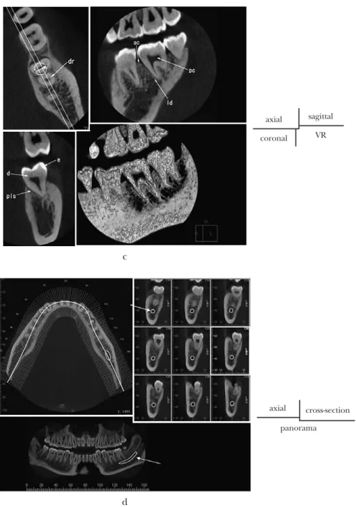
(5) 136. Yajima A et al.. axial. sagittal. coronal. VR. axial. sagittal. coronal. VR. a. axial. sagittal. coronal. VR. b Fig. 4. with dental software (Fig. 3). The projection data are reconstructed so as to allow simultaneous provision of as many as 512 MPR frames. The standard displays are axial, coronal, and sagittal MPR frames in three orthogonal planes.. Anatomical Depiction of Maxillofacial Region (Fig. 4) As CB Throne® voxels are intrinsically. isotropic images can be re-orientated so that anatomical features may be seen accurately in any plane. This is important for images of the maxillofacial region, which are structurally complex. Skeletal details of the maxilla and the mandible (a), including the temporomandibular joint (b), are clearly demonstrated using I-mode. Teeth structures are also better depicted using D-mode (c) than conventional CT. In addition to cross-sectional images, the dental software generates corresponding partial panoramic images after the curve.
(6) 137. Clinical Application of Cone-beam CT. axial. sagittal. coronal. VR. c. axial. cross-section. panorama. d Fig. 4 Anatomical structures on MPR image and dental reformatted images a: Maxillary and mandibular bone on MPR image using I-mode. Each number indicates as follows; 1–8: dental root (1. first incisor; 2. second incisor; 3. cuspid; 4. first bicuspid; 5. second bicuspid; 6. first molar; 7. second molar; 8. third molar), ans: anterior nasal spine, npc: nasopalatine canal, mp: maxillary process, ms: maxillary sinus, nc: nasal cavity, mb: mandibular body, mc: mandibular canal, mr: mandibular ramus, mf: mental foramen b: Temporomandibular joint on MPR image using I-mode. at: articular tubercle, js: joint space, mf: mandibular fossa, mc: mandibular condyle, eam: external auditory meatus, mac: mastoid air cell c: Teeth on MPR image using D-mode. dr: dental root, ac: alveolar crest, ld: lamina dura, pc: pulp canal, d: dentin, e: enamel, pls: periodontal ligament space d: Mandibular canals on dental reformatted images obtained from axial image using I-mode. Not only teeth, but also surrounding structures such as mandibular canals (arrow) are demonstrated in cross-sectional and panoramic views..
(7) 138. Yajima A et al.. a. MPR axial. MPR sagittal. MPR coronal. VR. axial. cross-section. panorama. b. c. Fig. 5. MPR axial. MPR sagittal. MPR coronal. VR. MPR axial. MPR sagittal. MPR coronal. VR.
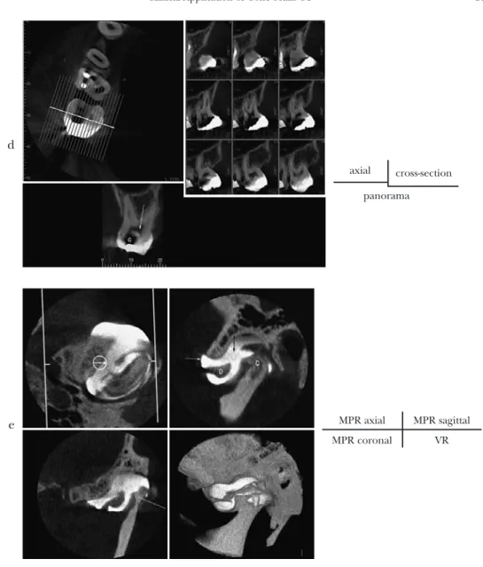
(8) 139. Clinical Application of Cone-beam CT. d axial. cross-section. panorama. e. MPR axial. MPR sagittal. MPR coronal. VR. Fig. 5 Clinical cases a: Impacted canine in left maxilla, using D-mode (13-year-old girl). “S” and “B” indicate second incisor root and first bicuspid, respectively. b: Root fracture of incisor in right maxilla using D-mode (10-year-old girl). c: Radicular cyst of second incisor in right maxilla, using D-mode (a 32-year-old man). “R” indicates root apex. d: Caries of second molar in right maxilla, using D-mode (36-year-old woman). “C” indicates dental caries. e: Disk perforation at TMJ (49-year-old woman). “C” and “D” indicate condyle and perforated disk, respectively. CBCT imaging was performed using I-mode after injection of contrast media into upper joint space (white arrow).. marking the dental arch is defined on an axial image obtained by I-mode (d). These images can show bone status, as well as the relationship between the teeth and the surrounding anatomical structures such as the mandibular canal.. Clinical Examples of Maxillofacial Region Images (Fig. 5) Several reports have shown that the CB Throne® was of value in evaluating conditions and pathoses of the dentition, jaw, and.
(9) 140. Yajima A et al.. a. b. axial. cross-section. panorama Fig. 6 Preoperative distance measurement in left molar region of maxilla for dental implant planning (57-year-old woman) Figure 6-a shows the corresponding cross-sectional (cross-section) and panoramic images (panorama) obtained along the axis selected on the curved line. In Fig. 6-b method of measurement is shown on magnified cross-sectional image. Distance from alveolar crest to bottom of maxillary sinus is 9.8 mm. Alveolar width was approximately 5.6mm at slice.. temporomandibular joint in the oral and maxillofacial field2,3). The CB Throne® has been used to evaluate a variety of conditions and tasks. In Fig. 5a, MPR and VR images, cross-section images, and panoramic images reveal that the left canine (arrow) is slightly impacted horizontally. The crown is located adjacent to the second incisor root, and the root is close to the root of the first bicuspid. The apex of the root is curved. In Fig. 5b, the fracture line (arrow) is visible in any plane on an MPR and VR image. The space between the fractured segments appears minimal. The widening of the periodontal ligament space is observed. There is no significant bone loss in the alveolar process. In Fig. 5c, MPR and VR images reveal a lesion (arrows) with a welldefined cortical boundary in maxilla. The epicenter of the lesion is located at the root apex of a nonvital second incisor in the right. maxilla. Dental caries can be detected efficiently by means of intraoral films, and the CB Throne® also allows detection of caries. In Fig. 5d, reformatted dental images show that caries has reached the dental pulp (arrow) at the distal surface of the right first molar. In this situation caries would not appear on images provided by conventional CT due to artifacts from metal restorations. Moreover, the CB Throne® allows arthrography of the temporomandibular joint, making it a useful tool in the diagnosis of perforation of the joint articular disk. In Fig. 5e, an MPR image shows the flow of a contrast agent into the lower joint space from the upper joint space (black arrow), where the disk was perforated. There is erosive change at the top of the condyle. A VR image shows the contrast media in the upper and lower joint spaces..
(10) Clinical Application of Cone-beam CT. Preoperative Distance Measurement for Dental Implants (Fig. 6) The development of dental implant surgery necessitates easily comprehensible volumetric maxillo-mandibular imaging. Due to its high spatial resolution in any plane and dimensional accuracy, the CB Throne® system could play a major role in three-dimensional visualization and prediction in preoperative examination of the jaw for dental implants. Moreover, the CB Throne® system provides dose savings by restricting the exposure field to fit adjusted FOVs. The CB Throne® can generate detailed cross-sectional pictures of the jaw area in which prospective dental implant treatment is being planned.. 3). 4). 5) 6). 7). Conclusion We believe our findings clearly indicate the clinical validity of the newly-developed CBCT system, CB Throne®, in hard-tissue visualization of maxillofacial lesions and preoperative evaluation of dental implants.. References 1) Abrahams JJ (2001) Dental CT imaging: a look at the jaw. Radiology 219:334–345. 2) Arai Y, Tammisalo E, Iwai K, Hashimoto K, Shinoda K (1999) Development of a compact. 8). 141. computed tomographic apparatus for dental use. Dentomaxillofac Radiol 28:245–248. Araki K, Maki K, Seki K, Sakamaki K, Harata Y, Sakaino R, Okano T, Seo K (2004) Characteristics of a newly developed dentomaxillofacial X-ray cone beam CT scanner (CB MercuRay): system configuration and physical properties. Dentomaxillofac Radiol 33:51–59. Baba R, Konno Y, Ueda K, Ikeda SR (2002) Comparison of flat-panel detector and imageintensifier detector for cone-beam CT. Comput Med Imaging Graph 26:153–158. Kalender WA (2000) Chapter 4. Image quality, Computed Tomography, pp.102–113, MCD: Werbeagentur GmbH, Munich. Mozzo P, Procacci C, Tacconi A, Martini PT, Andreis IA (1998) A new volumetric CT machine for dental imaging based on the cone-beam technique: preliminary results. Eur Radiol 8:1558–1564. Yamamoto M, Curtin HD, Suwansa-ard P, Sakai O, Sano T, Okano T (2004) Identification of juxtaforaminal fat pads of the second division of the trigeminal pathway on MRI and CT. Am J Roentgenol 182:385–392. Ziegler CM, Woertche R, Brief J, Hassfeld S (2002) Clinical indications for digital volume tomography in oral and maxillofacial surgery. Dentomaxillofac Radiol 31:126–130.. Reprint requests to: Dr. Aya Yajima Department of Oral and Maxillofacial Radiology, Tokyo Dental College, 1-2-2 Masago, Mihama-ku, Chiba 261-8502, Japan Tel: +81-43-270-3961 Fax: +81-43-270-3963 E-mail: [email protected].
(11)
図
+2

関連したドキュメント
Study on Dental Treatment with YAG Laser 1st Report -Temperature of Dental Tissue Irradiated with Laser Beam -.. Takashi UEDA, Keiji YAMADA and
Objective: The present study was performed to investigate the feasibility of fusion of images obtained by SPECT and multidetector CT (MDCT) for the accurate localization of
Certain meth- ods for constructing D-metric spaces from a given metric space are developed and are used in constructing (1) an example of a D-metric space in which D-metric
Certain meth- ods for constructing D-metric spaces from a given metric space are developed and are used in constructing (1) an example of a D-metric space in which D-metric
また適切な音量で音が聞 こえる音響設備を常設設 備として備えている なお、常設設備の効果が適 切に得られない場合、クラ
OFFI CI AL SCORE CERTI FI CATE GTEC (4技能) (CBT可). Test Repor t For m I ELTS™(Academi c
(Furthermore, a bound on the number of elementary matrices can be found that depends only on n, and is universal for all fields.) In the case of fields, this can easily be
・ここに掲載する内容は、令和 4年10月 1日現在の予定であるため、実際に発注する建設コンサル
