Development of Novel Technology for Waste
Water Treatment Using Ultrasonic Cavitation
and Underwater Plasma
著者
Fang Yu
学位授与機関
Tohoku University
学位授与番号
11301甲第18798号
Development of Novel Technology for
Waste Water Treatment Using Ultrasonic Cavitation and
Underwater Plasma
(超音波キャビテーションと水中プラズマを併用した廃水無害化
新規技術の開拓)
Yu Fang
Supervisor: Prof. Sergey Komarov
Graduate school of Environmental Studies
TOHOKU UNIVERSITY
Committee in Charge
Professor, Sergey KOMAROV, Chair
Professor, Eiki KASAI
Professor, Kazuaki WAGATSUMA
Abstract
A novel wastewater treatment process, acoustic cavitation assisted plasma (ACAP) is proposed in this study aiming at expanding the treatable range of water pollutants due to a synergetic effect of ultrasound irradiation and high voltage plasma discharge, consequently achieving efficient pollutant degradation. In this process, the role of acoustic cavitation is not only to provide generation of chemically active OH radicals, as for example in conventional ultrasonic wastewater treatment techniques, but also to ensure conditions for stable plasma generation in wastewater and, thus, to extend the treatable range of water pollutants.
Preliminary investigations on radical generation were performed in both batch and circulatory ultrasonic reactor by KI method. Numerical simulation on acoustic streaming has been performed to illustrate effects on radical generation in two types reactor. Results showed that radical generation rate in batch type is much higher than that in circulatory type due to the better mass transfer via acoustic streaming. Flow rate showed limited effects on radical generation in the circulatory ultrasonic reactor.
Then the studies on characteristics of plasma discharge were conducted in the self-made ACAP setup. The optimal distance of spark gap and electrode distance were obtained to generate stable spark discharge with low energy consumption. ACAP setup allows to increase the acceptable range of electrical conductivity of treatable solutions up to 1000 μS/cm, that is about 24 times higher than in the case of conventional plasma discharge treatment. While the pH and ultrasound power showed insignificant effects on spark discharge generation.
Rhodamine B was used as a model pollutant in experiments examining effects of ultrasound power, RhB initial concentration, output voltage, solution pH, electrical conductivity and flow rate on the RhB degradation efficiency both in batch and circulatory reactors. The alkaline and acid medium were found to be favorable for higher degradation efficiency. Efficient degradations were obtained in 2.5 mg/L initial concentration and 32 kV output voltage. In batch reactor, a maximum degradation efficiency was observed at 20 µS/cm,
whereupon it decreased with electric conductivity growth, while the maximum value was obtained at 100 µS/cm in circulatory reactor. Flow rate growth resulted in better degradation due to improved mass transfer, which was verified by numerical simulation on acoustic streaming and circulatory flow.
Additional measurements and results of recent investigations concerning underwater plasma showed that microbubbles presented in cavitation zone could serve as “step stone” making the pulse discharge propagation between the electrodes easier than in the conventional case. Besides, acoustic cavitation assists a faster transition of plasma discharge from ineffective streamer type to more effective spark type that further contributes to the improvement of the treatment performance.
Keywords: Ultrasound; cavitation; plasma discharge; acoustic streaming; water
treatment; Rhodamine B degradation; numerical simulation; batch and circulatory
reactor.
Outline
1. Introduction ... 1
1.1. Advanced Oxidation Processes (AOPs) ... 1
1.1.1. Fenton processes ... 3
1.1.2. Ozone process ... 4
1.1.3. H2O2 process ... 4
1.1.4. O3/ H2O2 process ... 5
1.1.5. Electron beam irradiation process ... 5
1.1.6. Photocatalysis processes ... 5
1.2. Water treatment by plasma ... 6
1.2.1. Underwater non-thermal plasma discharge ... 7
1.2.2. Mechanism of underwater plasma discharge ... 9
1.2.3. Underwater plasma discharge types ... 10
1.2.4. Researches on underwater plasma ... 11
1.3. Water treatment with ultrasound technology ... 15
1.3.1. Characteristics of ultrasound techniques and sonochemistry ... 15
1.3.2. Acoustic cavitation ... 16
1.3.3. Acoustic streaming ... 17
1.3.4. Researches on application of ultrasound to water treatment ... 18
1.4. Researches on combination of ultrasound and plasma ... 21
1.5. Purpose of this research ... 22
2. Experimental setup and methodology ... 25
2.1. Experimental setup ... 25
2.1.1. Setup for research on radical generation by ultrasound irradiation ... 25
2.2. Analyzing method ... 29
3. Radical measurement by KI method in batch and circulatory ultrasonic reactor ... 31
3.1. Calorimetric measurement ... 31
3.1.1. Measurement principle ... 31
3.1.2. Heat loss ... 32
3.1.3. Measurement results ... 33
3.2. Weissler reaction ... 34
3.3 Radical generation with various parameters ... 35
3.3.1 Effect of power change during ultrasound irradiation in circulatory reactor 35 3.3.2 Effects of flow rate in circulatory reactor ... 37
3.3.3 Effects of output power in batch reactor ... 40
3.3.4 Effects of ultrasound power in circulatory reactor ... 41
3.4 Numerical simulation on cavitation zone and acoustic streaming ... 42
3.4.1 Cavitation zone ... 43
3.4.2 Acoustic streaming ... 48
4. Effects of acoustic cavitation on underwater plasma discharge ... 51
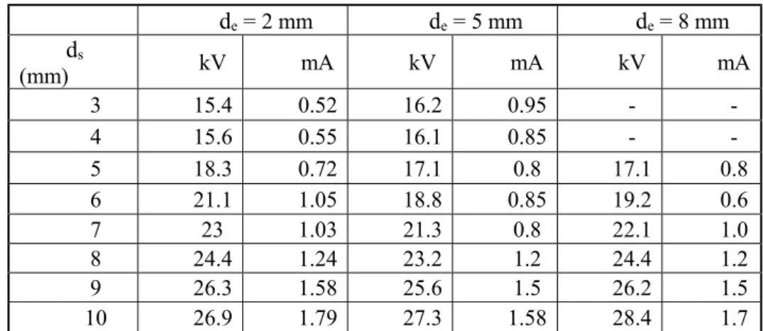
4.1. Effects of spark gap distance (ds) and electrodes distance (de) on spark discharge without cavitation ... 51
4.2. Expanded available pH and electric conductivity ranges of spark discharge generation 52 4.3. Energy efficiency of spark discharge in ACAP process ... 53
5. Rhodamine B degradation in ACAP process in batch reactor ... 57
5.1. Effects of initial concentration ... 57
5.2. Effects of initial pH ... 58
5.4. Effects of output voltage ... 61
5.5. Effects of ultrasound power ... 61
6. Rhodamine B degradation by ACAP process in circulatory reactor ... 63
7. Mechanism of Rhodamine B degradation and synergistic effect in ACAP process 64 7.1 Mechanism of Rhodamine B degradation in ACAP process ... 64
7.2 Mechanism of acoustic cavitation-assisted plasma discharge ... 64
7.2.1 Plasma propagation ... 64
7.2.2 Synergistic effect of acoustic cavitation-assisted plasma ... 69
8. Conclusion... 72
8.1 Overview of research ... 72
8.2 Future works ... 73
Reference ... 74
1
1. Introduction
1.1. Advanced Oxidation Processes (AOPs)
With the developments of modern society and industries in past decades, wastewater has become a vital problem to human beings. Those industrial effluent usually contains complex and toxic contaminants (especially refractory organic pollutants) and with low biodegradability. To eliminate potential threats of those effluents to the human beings and natural environment, it is urgent to develop effective and efficient ways to treat wastewater.
Conventional wastewater treatment methods include physical, chemical and biological degradation processes, such as aerobic and aerobic treatment processing. However, those processes are unable to totally decompose and mineralize hazardous organic pollutants, such as polycyclic aromatic hydrocarbon and phenolic compounds. Some intermediates generated in these conventional processes are even more toxic. It rises high requirements to treatment and operation const to degrade those pollutants. Therefore, highly efficient treatment processes are the hot topics in the research field of water pollution control.
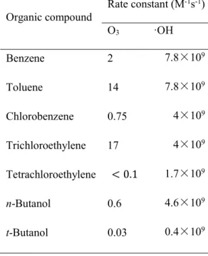
Advanced oxidation processes (AOPs) have been paid great attentions since 1980s. By generating highly reactive oxidants, mainly the hydroxyl radical, the pollutants can be degraded in the process, and finally mineralized without secondary pollution. Table 1.1 shows the oxidation potential of common species [1]. Here conventional oxidants such as chlorine, permanganate and ozone are compared to the hydroxyl radical, which shows that hydroxyl radical is the most powerful oxidizing species after fluorine. The aim of most AOPs is to produce the hydroxyl radical in water, since hydroxyl radical can oxidize many organic compounds significantly faster than other oxidant species. Table 1.2 gives the comparisons of rate constants for ozone and hydroxyl radicals.
2
Table 1.1 Oxidation potential of common species Oxidant Species Oxidation
potential (V) F2 3.03 ·OH 2.80 ·O 2.42 O3 2.07 H2O2 1.78 HO2+ 1.70 MnO4- 1.68 ClO4- 1.63 ClO2 1.50 Cl2 1.36 Cr2O32- 1.33 O2 1.23
Table 1.2 comparisons of rate constants for ozone and hydroxyl radicals
Organic compound Rate constant (M-1s-1) O3 ·OH Benzene 2 7.8×10⁹ Toluene 14 7.8×10⁹ Chlorobenzene 0.75 4×10⁹ Trichloroethylene 17 4×10⁹ Tetrachloroethylene < 0.1 1.7×10⁹ n-Butanol 0.6 4.6×10⁹ t-Butanol 0.03 0.4×10⁹
3
In 1894, Fenton [2] found that hydroxyl radicals can be generated from reaction between Fe2+ and H
2O2, and then the hydroxyl radicals mineralize organic pollutants in water into carbon
dioxide and water through electron transfer. Bader presented that O3 reacts with OH- in aqueous
solution and yields hydroxyl radical in 1935[3]. Then in 1948, Taube and Bray [4] found that H2O2 disaggregates into HO2- in aqueous solution, and induces the generation of hydroxyl
radical. The hydroxyl radical can also be generated by applying physical methods, such as ultrasonic irradiation, hydrodynamic cavitation, electron beam, and also supercritical water oxidation, wet air oxidation, catalytic wet air oxidation and so on [5, 6]. In 1970s, Fujishima and Honda [7] revealed that hydroxyl radical can be generated by photocatalysis, which opened up a new world for researches on the advanced oxidation processes. However, the radical generation rate and pollutant degradation efficiency have been usually low. Recently, hybrid advanced oxidation processes (HAOPs) has attracted attention due to their high efficiency when combining several AOPs. As a result, proposed a promising way for industrial applications has been proposed. HAOPs usually include ultrasound/H2O2 (or O3), UV/ H2O2 (or O3), H2O2 /O3,
sono-photochemical oxidation, Fenton-photocatalysis, combination with bio-oxidation process and coupling oxidation process, such as sonochemical degradation followed by wet air oxidation [8].
1.1.1. Fenton processes
In Fenton processes, hydroxyl radical is generated by the Fenton reaction, which is the reaction between Fe2+ and H
2O2. It can be simply written as follows:
𝐹𝑒 + 𝐻 𝑂 → 𝐹𝑒 + 𝑂𝐻 +∙ 𝑂𝐻 (1-1)
When applying a UV irradiation with the wavelength below 400 nm, the Photo-Fenton reaction is induced. It compromises a series of complex reactions including the photochemical reaction of Fe3+ transmitting to Fe2+, which significantly accelerates the following reactions [9]:
4
𝐹𝑒 + 𝐻 𝑂 → 𝐹𝑒 + 𝑂𝐻 +∙ 𝑂𝐻 (1-3)
𝐹𝑒 + 𝐻 𝑂 + ℎ𝑣 → 𝐹𝑒 + 𝐻 +∙ 𝑂𝐻 (1-4)
Therefore, Photo-Fenton has a higher efficiency in pollutants degradation than Fenton process.
1.1.2. Ozone process
Ozone can be decomposed into O-based radicals in aqueous solution. But these radicals usually have relatively low reaction rate and narrow treatable pollutant categories. However, in the alkaline solution (high pH), the existence of OH- accelerates the disaggregation of ozone,
which yields a large amount of hydroxyl radical [10-12]. It can be written as:
𝑂𝐻 + 𝑂 →∙ 𝑂 +∙ 𝐻𝑂 k = 70L/(mol ∗ s) (1-5) ∙ 𝐻𝑂 ↔∙ 𝑂 + 𝐻 p𝐾 = 4.8 (1-6) ∙ 𝑂 + 𝑂 →∙ 𝑂 + 𝑂 k = 1.6 × 10 mol/L (1-7) ∙ 𝑂 + 𝐻 →∙ 𝐻𝑂 k = 5.2 × 10 mol/L (1-8) 𝐻𝑂 →∙ 𝑂𝐻 + 𝑂 k = 1.1 × 10 mol/L (1-9) 1.1.3. H2O2 process
Due to its low cost and high availability, H2O2 has been widely used in industrial effluent
treatment, waste gas treatment and disinfection processes. H2O2 in aqueous solution can be
decomposed into HO2- , which induces generation of hydroxyl radicals [8]:
𝐻 𝑂 → 𝐻𝑂 + 𝐻 (1-10)
With the irradiation of UV light (wavelength below 400 nm), that means UV/ H2O2
process, the hydroxyl radical generation is accelerated.
5 1.1.4. O3/ H2O2 process
In the O3/H2O2 process, namely Peroxone Chemistry Process, the hydroxyl radical
generation rate is much higher than that when the ozone or H2O2 is used singly [13, 14]. The
Peroxone reaction can be written as:
2𝑂 + 𝐻 𝑂 → 2 ∙ 𝑂𝐻 + 3𝑂 (1-12)
This process achieves better efficiency in high pH solutions, and in the actual process, the dosage amount of ozone and peroxide can be determined according to (1-12), allowing the process efficiency to be optimized.
1.1.5. Electron beam irradiation process
Electron beam irradiation processes have already been applied in industries for wastewater
treatment, mud treatment and disinfection processes. By utilizing γray or high energy electron
clusters (0.5~2MeV) from electron accelerator or 60Co irradiation source, water itself and
pollutants in water can be decomposed. The decomposed products of water include eaq-, ions,
excited particles, hydroxyl radical, hydrogen atom and other radical species, which are highly reactive, thus be able to degrade pollutants in water [15]–[17].
𝐻 𝑂 → 𝑒 .+∙ 𝑂𝐻 +∙ H + 𝐻 + 𝐻 𝑂 + 𝐻 + 𝑂𝐻 . (1-13)
1.1.6. Photocatalysis processes
Nano-TiO2 semiconductor (band-gap energy of anatase type nano-TiO2 is 3.2 eV, which
is equivalent to 387.5nm photon quantity) is the most typical catalyzer applied in photocatalysis process. When irradiated by UV light at the wavelength below 387.5 nm, electrons are excited and transferred from valence band to conduction band, and the corresponding electron holes (hvb+) are formed in valence band, namely electron(ecb-)-hole pair [7], [18]:
6
Some electrons in conduction band recombine with the electron holes in valence band, and release heat:
𝑒 + ℎ → ℎ𝑒𝑎𝑡 (1-15)
If there is a proper trapping agent or surface defect states, the recombination of electrons and electron holes will be inhibited, and the oxidation and reduction reactions occur on the surface of TiO2. In most photocatalysis reactions, oxidation ability of electron holes is directly
or indirectly utilized. Electron holes are highly reactive, usually react with surface absorbed H2O and OH-, consequently yield hydroxyl radicals:
ℎ + 𝐻 𝑂 →∙ 𝑂𝐻 + 𝐻 (1-16)
ℎ + 𝐻𝑂 →∙ 𝑂𝐻 (1-17)
Hydroxyl radical, •O2- radical and •HO2 radical are generated in the photocatalysis
process. These radicals can degrade organic pollutants directly or indirectly into small molecule
intermediates, and finally mineralize them [19]. The ℎ can also directly degrade pollutants
[20].
As mentioned above, similar to these advanced oxidation processes, which also include electrochemical oxidation, electrical-catalysis oxidation and electric-photocatalysis oxidation processes, plasma and ultrasound techniques are aiming at generating highly reactive and non-alterative hydroxyl radical. These two techniques will be discussed in details in the next parts.
1.2. Water treatment by plasma
Similar as the commonly known solid, liquid and gas phases, plasma is the fourth phase state, which creates approximately 99% of the observable universe. Plasma in the physical or chemical sense is in principle an ionized gas. Free electric charges – electrons and ions, which make plasma electrically conductive (sometimes even more than gold or copper), internally interactive and strongly responsive to electromagnetic fields. Due to this fact, plasma becomes a very interesting topic from the chemical or physical point of view. As temperature increases, molecules start to be more energetic which leads to the matter transformation. Ionized gas is
7
usually called plasma when it is electrically neutral in large volume (the electron density is balanced by positive charges) and contains a significant number of the electrically charged particles, sufficient to affect its electrical properties and collective behavior.
Plasma can be defined into two groups according to the temperature of plasma channel and particles, thermal plasma (or thermal equilibrium plasma) and non-thermal plasma (or cold plasma) respectively. In thermal plasma, temperature of electron and ions are the same, which are kept in the thermal equilibrium, usually above 5000 K. In non-thermal plasma, although the temperature of electrons can be as high as 105 K, other ions and plasma channel are at a
temperature of 300~500 K in average. Thus, electrons are at a non-equilibrium state with other particles. Non-thermal plasma could be generated at the normal pressure and temperature. Therefore, it is a promising technique for industrial applications.
1.2.1. Underwater non-thermal plasma discharge
The generation of electrical discharges in liquids, such as water, can be used to produce a variety of chemically reactive products, which include free radicals, ions, high energy electrons, UV light, and shock waves. These products and phenomenon e can be applied to engineering problems ranging from the decomposition of volatile organic compounds (VOC) and dyes in industrial waste to the development of point-of-use water purification [21]–[24]. Highly
reactive chemical products, such as H2O2, •OH and O-, are generated during the plasma
discharge in water [25]. These products are of high oxidation potential, which makes them strongly reactive to organic compounds. Ozone is a radical product which has already been widely applied for industrial purification purposes. However, the most substantial contributor to high reactivity in plasma treatment processes is believed to be hydroxyl radical because of its high oxidation potential and high reaction rate constant, as shown in Table 1.1 and 1.2 [21]. Table 1.3 shows the most important reactions during the plasma discharge. Production of high energy electrons provides energy necessary for the chemical reaction activation. These
8
reactions initiate a series of chain reactions to generate reactive species. Here, 𝐴∗ means an any
particle in an excited state, and 𝐴∙ means a free radical.
Table 1.3 Reactions during the plasma discharge Ionization: 𝑒 ∗+ A → 2𝑒 + 𝐴
Dissociation: 𝑒 ∗+ 𝐴 → 2𝐴∙+ 𝑒
Excitation: 𝑒 ∗+ A → 𝐴∗+ 𝑒
Electron Capture: 𝑒 ∗+ A + 𝐵 → 𝐴 + 𝐵
For plasma discharge in water, the reactant A is H2O. In this case, dissociation plays a vital
role in generating •OH and •O. In the secondary reactions, another reactive species, H2O2, can
be generated by hydroxyl radical combination. The mechanisms of organic compound degradation by hydroxyl radical are mainly demethylation, demethylation and addition of hydroxyl [26]. In both the approaches, hydrogen atom in the organic molecule is attacked by a hydroxyl radical. As a result, the hydrogen atom is converted into a highly reactive radical. Through this process, the pollutant compound is eventually converted to harmless products. The ordinary abstraction process of an organic compound, RH, can be written as follows:
𝑅𝐻 +∙ 𝑂𝐻 → 𝐻 𝑂 + 𝑅∙ (1-18)
2 ∙ 𝑂𝐻 → 𝐻 𝑂 (1-19)
𝑅∙+ 𝐻 𝑂 → 𝑅𝑂𝐻 + 𝑂𝐻∙ (1-20)
𝑅∙+ 𝑂 → 𝑅𝑂𝑂∙ (1-21)
𝑅𝑂𝑂∙+ 𝑅𝐻 → ROOH + R (1-22)
The mechanism of radical production in liquid plasma discharge provides a promising solution for applications requiring reactive chemistry. The following parts will give a concise overview of recent researches on underwater plasma. Before that, it is needed to introduce the mechanism of various underwater plasma discharge generation, and the various discharge types, which significantly affect the radical generation, and consequently has a great influence on the pollutant’s removal.
9 1.2.2. Mechanism of underwater plasma discharge
In general, underwater plasma process requires an application of high energy injection into water medium and consequently induces charge accumulation and discharge ignition. The electric energy transfers by plasma channel which generated discharge between immersed electrodes. To generate such discharges, three electrode configurations have been commonly applied, as showed in Figure 1.1.
Figure 1.1 Various electrode configurations: (a) couple plane electrodes, (b) point-to-plane and (c) pin-hole electrodes
Figure 1.1 (a) shows a simple construction of two parallel plane electrode. This structure is undesirable for underwater plasma discharge due to the high breakdown electric field strength in water (1 MV/cm). Applying this construction requires high input voltage or very short distance between electrodes, which would cause high energy consumption and reduces the capability of water treatment. In the case of the other two electrode configurations, point-to-plane structure results in a highly condensed electric field on the tip of point electrode, which makes it much easier to breakdown. In the pin-hole configuration, two electrodes are separated by dielectric barrier with small holes, and consequently the local electric field intensity becomes extremely high on the holes.
The mechanism of plasma generation in liquids are still unclear. Generally, there are two main theories describing it, the electron and bubble theories [27]. According to the electron theory, free electrons are accelerated due to a high-intense electric field at the tip of the
point-10
to-plate system. These accelerated electrons collide and ionize other molecules, which produce additional electrons and thus cause the electron avalanche (plasma channel). This phenomenon results in the breakdown of liquid. The DC pulse discharge is usually applied in this process, so that electrons move toward the positive high voltage electrode. The applied positive voltage also attracts other electrons formed during the secondary avalanche. When the secondary electrons mix with the ions formed during the primary avalanche, positive space charges are formed on the top of streamer and the intensity of electric field is increased again at the end of streamer. This propagation allows a new avalanches development because positive charges attract electrons formed during other secondary avalanches. The bubble theory assumes that joule heating effect of high-dense current in the electric field evaporates the liquid, and then bubbles are formed. Then the plasma channel can propagate in the liquid by passing through the vapor phase.
There are also other theories concerning the liquid plasma discharge mechanism. Such as that the electric field is supported by hydrogen ion, electron, hydroxyl ion, which generated during water molecular dissociation. These ions produce a high conductive area from which a streamer spreads as an ionization wave. Another theory, which explains the streamer propagation, is based on a water evaporation phenomenon at the top of streamer. A streamer resistance has been measured to be much lower than that of water [28].
1.2.3. Underwater plasma discharge types
Two primary modes of discharge can be observed in the case of underwater plasma: the streamer discharge and spark discharge. In a streamer discharge, the plasma channel branches grow from the electrode surface and do not make contact with the opposite electrode, as shown in Figure 1.2 (a). If the voltage becomes larger enough or the electrodes are enough close to each other, the streamer channels can propagate to the opposite electrode surface, and build a low conductivity plasma channel known as spark, showed in Figure 1.2 (b).
11
Figure 1.2 Schematic representation of (a) streamer discharge and (b) spark discharge in underwater plasma
Temperature in the spark discharge plasma channel may reach 14,000−50,000 K and plasma emits strong UV light and intense shock waves [29]. These factors contribute to the higher rate of radical production in the spark discharges. In the case of streamer discharge, a large amount of energy is spent for raising the temperature of water, leading to energy waste. This temperature increase is caused by the high current flowing through the conductive channels. The voltage required to ignite the plasma directly in the liquid is in the range 10 ~ 100 kV depending on the tip shape and gap distance of electrodes. The key parameter is the critical electric field for breakdown, which is typically ∼1 MV cm−1. In cases where the pulse
duration exceeds ∼100 ns, Joule heating and electrostatic stress can result in formation of small voids or micro bubbles near the electrode surface [30]. The pulse duration in most cases is very short, in the range 10 ~ 1000 ns, which minimizes the thermal heating of liquid.
1.2.4. Researches on underwater plasma
As a promising approach for water treatment, underwater plasma discharge has been paid great attention. Recent researches mainly have focused on the following aspects: physical effects, chemical effects and pollutants degradation.
12
(1) Physical effects of underwater plasma. The investigations on physical effects of underwater plasma have concerned phenomena related to generation of light, sound and shock wave. However, due to the limitations in measurement devices and techniques, the results are very limited.
Table 1.4 Recent researches on physical effects of underwater plasma discharge
Author Research Topic Main conclusion
Clements et al.
Generation of underwater plasma discharge
The phenomenon of spot discharge, red streamer branches, local micro discharge and micro bubbles were observed. [31]
Lisitsyn et al.
Generation of streamer plasma channel
The released energy during plasma channel propagation induced evaporation of water molecules in plasma channel. The ionic current density had a negative effect on plasma channel formation. [32]
Sun et al. Degradation effects of light irradiation by plasma
15% phenol degradation was attributed to the UV irradiation. [33]
Lukes et al.
Effects of electric conductivity on UV irradiation
Higher electric conductivity induced stronger UV irradiation. [14]
Belosheev et al.
Effects of current and electric conductivity on plasma channel formation and lengths
Increased electric conductivity resulted in higher current in plasma channel, while the plasma channels were shortened. [34]–[36]
Sun et al. Acoustic research on streamer and spark discharge
Acoustic pulses were observed in high electric conductivity. With the same input energy, discharge type did not affect sound intensity. [37]
(2) Researches on chemical effects in underwater plasma discharge mainly have focused on detecting and measuring generation of radicals, as shown in Table 1.5.
13
Table 1.5 Recent researches on chemical effects of underwater plasma discharge
Author Research Topic Main conclusion
Clements et al.
High voltage pulse discharge with a injector electrode
Ozone was detected after oxygen injection. While no ozone was detected with nitrogen injection. [31]
Sato et al. Radical measurement in water by spectrometer
•H and •OH were detected in the plasma channel area. The highest •OH yielded at the 10 µS/cm. H2O2 was formed from
•OH recombination.[38]
Sun et al.
Effects of bubbling gas (oxygen and Argon) on radical generation in discharge area
Radical intensity increased with the oxygen concentration up to 50 ml/L. • O radical existed in both bubbling and no bubbling conditions. [39]
Effects of electric conductivity on radical intensity
A maximum yield of radical was obtained at 10~80 µS/cm, then decreased with a continuous electric conductivity growth. [39]
Effects of discharge types on radical generation by spectrometer
Hydroxyl mainly formed in plasma channels. Spark discharge yields higher radical intensity than streamer discharge. The range of radical irradiation of spark discharge is 400~500 nm. [40]
Ono et al.
Hydroxyl generation of corona discharge in humid gases by LIF
A certain amount of hydroxyl radical formed in corona discharge in mixing humid gas (Nitrogen, Oxygen). Concentration of hydroxyl increased with Nitrogen ratio. [41]
Ozone and hydroxy generation of corona discharge in humid gases
Ozone yield was inhibited by vapor increment. Hydroxyl density in H2O(2.4%)/N2 was 3×1015 cm-3.[42]
Joshi et al.
Hydroxyl, H2O2 and high
energy yield ratio predictions on the model by applying bicarbonate ion as radical scavenger
Hydroxyl and H2O2 yielding related with electric field
14
Burlica et al.
Effects of various bubbling gases (Oxygen, Nitrogen and Dry air) on H2O2 ozone
generation
Electric conductivity was a function of gas source and pH. The generations of hydrogen molecule, oxygen ion and radicals attributed to the ionization by high energy electrons. [44]
(3) Researches on pollutant degradation by underwater plasma discharge have been widely conducted including such pollutants as aromatic compounds, C2Cl4, MTBE, BTEX and dyes
[86].
Table 1.6 Recent researches on pollutant degradation by liquid plasma discharge
Pollutants Researchers Main works
Phenol
Sharma et al. Conducted phenol degradation in the early stage, proved the phenol can be degraded by pulsed corona discharge. [45]
Sun et al.
Effects of bubbling and gas sources on phenol degradation were investigated, and the intermediates were analyzed. [33], [46]
Lukes et al.
Investigated the mechanism of high voltage discharge in gas-liquid phase, also includes the generation of radicals. [14]
Grymonpre et al.
Proposed a model of Fe2+ and C addition improving phenol
degradation. The intermediates were also analyzed. [47]– [50]
Sugiarto et al.
Various discharge types on phenol degradation. Proposed the mechanism for better degradation efficiency by spark type. [51], [52]
He et al.
Effects of OH- on phenol degradation by ozone in gas phase.
[53]
Phenylamine Tezuka et al.
Degradation by contact glow discharge. The degradation reaction followed first-order kinetics, which attributed to the hydroxyl radical. [54]
15
Dyes
Clements et al.
Pre-breakdown phenomena with and without gas injection. The plasma channels could be prolonged in higher input voltage and wider pulse width. Anthraquinone can be degraded over 80%. [31]
Sugarito et al.
Rhodamine B, Chicago Blue and Helianthin Orange degradation in ring-barrel plasma reactor. More plasma channels observed in double ring electrodes, higher efficiency than single ring electrode. Spark type discharge was better for degradation than streamer discharge. [52]
Koprivanac et al.
Degradation on MY10, DO39, RR45 and RB137. Degradation processes conform to pseudo-first order kinetics. [55]
Njiatawidjaja et al.
Chicago Blue degradation in atomization wire-ring reactor. [56]
Malik et al.
MB degradation in plasma reactor assisted by injecting gas discharge produced ozone. [13]
Yang et al. Effects of parameters on AO II degradation in ozone assisted plasma reactor. [57]
Wang et al.
Effects of peak voltage and frequency of pulse, electric conductivity, pH and gas injection on AO7 degradation in needles-plate reactor. [58]
1.3. Water treatment with ultrasound technology
1.3.1. Characteristics of ultrasound techniques and sonochemistryUltrasound is a kind of mechanical wave with a frequency higher than 16 kHz (beyond the human hearing), typically in the range from 20 kHz to 10 MHz. Sonochemistry means enhancing chemical reactions or building new reactions due to ultrasound irradiation aiming at enhancing the chemical reaction rate or obtaining new reaction products. Researches on the sonochemical applications have been widely conducted in many fields that include biochemistry, organic and inorganic synthesis, electrochemistry, photochemistry,
16
environmental chemistry, chemical engineering optimization and so on. From the late of 1980s, breakthroughs in pollutants degradation, especially the refractory pollutants, using sonochemistry techniques have been made, which have demonstrated great potential of sonochemistry for industrial applications.
When ultrasound waves propagate through an elastic medium, it results in a variety of changes including the composition, structure and properties of medium due to interaction between the waves and medium. These changes are so-called ultrasound effects, which combine thermal, mechanical and cavitation effects.
(1) Thermal effects: During propagation of ultrasound waves in a medium, the sound wave energy is continuously absorbed by medium and converted into heat causing temperature rise.
(2) Mechanical effects: In the case of relatively low frequency, small absorption coefficient and short irradiation time, the thermal effects of ultrasound are insignificant. Thus, ultrasound effects can be attributed to mechanical phenomena, which include vibration displacement, velocity, acceleration and sound pressure. (3) Cavitation effects: Ultrasonic sonochemical effects are mainly achieved due to
acoustic cavitation. This phenomenon includes generation, growth, oscillation and collapse of cavitation bubbles under ultrasound irradiation. When the ultrasound irradiation is strong enough, a huge amount of fine bubbles is generated, which are called acoustic cavitation bubbles.
1.3.2. Acoustic cavitation
As mentioned above, tiny bubbles are generated in ultrasound wave, transmitted in liquids following compression and rarefaction cycles. When the negative pressure of rarefaction cycle exceeds attractive forces between the molecules of liquid, a void is formed. This void, or so-called cavity, is filled with the solvent vapor or dissolved gas. In the compression cycle, the
17
cavity does not totally collapse but continues to grow to form larger acoustic cavitation bubbles. When some bubbles expand to an unstable size, they violently collapse and generate high temperature and high-pressure zone (hot spots) where temperature and pressure can reach up to 4000 K and 100 MPa, respectively. High-speed micro jet flow is generated on the collapse, that induces thermal, chemical and biological reactions [59]. As a result, various pollutants can be efficiently degraded under these extreme conditions including chemical bond fractures, aqueous combustion, pyrolysis and radical reactions.
1.3.3. Acoustic streaming
When an ultrasound wave propagates through a medium, the wave energy is absorbed and converted into momentum of liquid, that induces a macro steady flow, which is referred to as” acoustic streaming”. Rayleigh proposed a theory on acoustic streaming first [60], [61], defined it as a steady flow phenomenon occurring when a sound wave propagates through a viscous fluid, and investigated the fluid field induced by standing wave between parallel dual plates. Then Eckart, Nyborg, Schlichting, Lighthill and Jackson investigated the acoustic streaming respectively [62] – [67]. Nyborg proposed that acoustic streaming is induced by Reynolds stress, while Schlichting and Lighthill proposed that acoustic streaming is attributed to sound wave energy attenuation.
Byoung-Gook Loh [68] investigated the acoustic streaming and its effects on enhancing the convection heat transfer, showed that the temperature of fluid near the sound source decreased by 40 ℃ in 4 minutes. A. Mandroyan [69] used PIV to study the fluid flow near sound source, showed that flow velocity was increased up to 0.5 m/s with the 20 kHz frequency and 900 W input power of ultrasound.
As the acoustic streaming is directed away from sonotrode tip surface, it can affect residence time of liquid in the zone of intense cavitation. Thus, this phenomenon is important
18
in the ultrasound related researches, especially for ultrasound processing in melt casting and waste treatment.
1.3.4. Researches on application of ultrasound to water treatment
The earliest study on applying ultrasound to water treatment has been reported in 1929 by E.N.Harvey [70] who used 375 kHz ultrasound to treat seawater with suspension bacillus. It was found for the first time that ultrasound effects on bacteria are more significant as compared to effects of heat. From then on, the ultrasound technique applications in water purification and pollutant degradation have been investigated continuously. There have been also many researches on combination of various techniques with ultrasound and other Advance Oxidation Processes (AOPs). These combined processes provide usually lower cost and higher treatment efficiency, which are more practical for industrial applications [71].
(1) US/H2O2/Fenton process:
Lin [72], [73] found that the combination of ultrasound with H2O2 increases the efficiency
of 2-CPOH decomposition significantly and investigated the effect of H2O2 concentration on
the decomposition. Addition of more H2O2 Addition yielded greater degradation efficiency,
while the effect of FeSO4 addition was insignificant. Nagata [74] studied the sonochemical degradation of chlorophenols and chlorobenzene with Fe (II) in the ultrasound condition of 200 W and 200 kHz. An optimum Fe (II) addition was found since the excessive Fe (II) performed as hydroxyl scavenger. Joseph [75] investigated the effect of FeSO4 on the sonochemical
degradation of azobenzene (AB) and related azo dyes (methyl orange (MO), O-methyl red (o-MR), p-methyl red (p-MR)) saturated with air, O2, and argon with the ultrasound of 500 kHz
and 50 W. It was shown that the maximum reaction rate constant was attained with an optimal Fe (II) concentration. Similarly, any further increase in Fe (II) concentration was showed to have no effect on the degradation improvement. Beckett [76] investigated the ultrasonic decomposition of 1,4-dioxane (1.0 mM) in the presence of Fe(II). It was shown that
19
decomposition rate and mineralization efficiency are improved at all frequencies examined in this study. Also, a 2-fold increase in mineralization was observed at an ultrasound frequency of 205 kHz and Fe(II) concentration of 10 mM Generally, the ultrasound enhancement effect decreased with increasing frequency.
(2) US/UV/H2O2/Fenton process:
Ku [77] found that the ultrasound degradation of 2-chlorophenol in the presence of O2 can
be improved when combining with UV irradiation and H2O2 addition. Toy [78] observed
synergistic effects of sonolysis and photolysis in the decomposition of aqueous 1,1,1-trichloroethane. Wu [79] found that the combination of ultrasound (30 kHz, 100 W) and photochemistry (18 W, 253.7 nm UV) was more effective in degrading aqueous phenol and oxidizing its subsequent intermediates than ultrasound or ultraviolet light alone. Naffrechoux [80] evaluated the efficiency of sonochemical effect in conjunction with photochemical irradiation for the degradation of phenol at pH of about 5.5 using ultrasound (485 kHz, 100W) alone, UV (15 µW, 253.7 nm) alone, and a combined “Sono-UV” reactor. They observed a significant enhancement in the pseudo-first-order degradation rate of phenol in the combined system. The synergistic effect was attributed to photo-decomposition, sono-decomposition, and ozone oxidation resulting from the transfer of O3 formed from O2 into solution.
(3) US/Ozone/UV processes:
Barbier [81] investigated the ultrasonic degradation and mineralization of 4-nitrophenol (4-NP) at frequencies of 20 and 500 kHz and various mixture gas. They found that the coupling of ultrasound and O3 increases the potential of ozonation to mineralize 4-NP degradation
products. In low pH condition, 4-NP mineralization at 500 kHz was faster than at 20 kHz for the same O3 consumption. Olson [82] studied the effectiveness of a “sono-ozone” process for
fulvic acid degradation. The combined system was found to significantly enhance the TOC removal and mineralization rates. The enhanced mineralization efficiency obtained with sonolysis was partially attributed to the direct combustion of volatile intermediates in cavitation
20
bubbles. Sierka [83] investigated the treatment of aqueous solutions of trinitrotoluene (TNT) and cyclotrimethylenetrinitramine (RDX) at 25-59 °C using a combination of ozone and ultrasound in the pH range of 5.84-10.00. They observed the synergistic effects of both ozone and ultrasound. Maximum destruction of both TOC and TNT was observed at 859 kHz and 50 W, while no removal was observed in experiments without O3. Lall [84] studied the
decolorization of the dye Reactive Blue 19 by ozonation, ultrasound, and ultrasound-enhanced ozonation using a semi-batch reactor. The apparent first-order rate constants for the ultrasound-enhanced ozonation were obtained. They also studied the effect of ultrasonic power input on the overall mass transfer coefficient of ozone in solution. The increase in overall rate was attributed to the combined effects of an increase in mass transfer and intrinsic kinetics resulting from cavitation. An increase in ultrasonic power also increases turbulence, which reduces the liquid film thickness and, hence, increases the mass transfer rate of ozone in solution.
(4) US/Wet Oxidation processes:
Aymonier [85] developed a hydrothermal sonochemical reactor with the objective of accelerating the oxidation rate of acetic acid in order to obtain comparable conversion at lower temperature and pressure than are used in standard SCWO operating conditions. They found that, at the optimal conditions of 2.8 MPa and 220 °C, ultrasonic activation (4000 W and 20 kHz) resulted in 83% degradation during 10 min treatment, an increase in the acetic acid oxidation by 40% higher than the experiments without ultrasound. Using a residence time distribution method, it was shown that ultrasonic cavitation actually induces an oxidation effect on the oxidation reaction, speeding up its kinetic rate. Ingale [86] investigated the degradation of a refractory component in the industrial waste of a cyclohexene oxidation unit using sonication followed by catalytic wet oxidation (SONIWO). It was shown that sonication in the presence of CuSO4 as a catalyst results in accelerated degradation of the unknown compound,
21
and the CuSO4 catalyst was superior to NiSO4 one. The SONIWO systems allowed achieving
a 66% decrease in COD compared with 36% for the simple CuSO4-catalyzed system.
1.4. Researches on combination of ultrasound and plasma
Combination of ultrasound and plasma in liquids is a promising technique for waste treatment due to the interaction between cavitation bubble, plasma streamer and acoustic streaming. When the cavitation bubbles are generated, micro plasma can ignite inside the bubbles, which could be helpful for plasma streamer propagation. Furthermore, the existence of huge amount of bubbles should decrease the breakdown voltage for plasma generation reducing energy consumption. In addition, the acoustic streaming could enhance the mass transfer inside the ultrasound reactor making bulk solution passing through the plasma generation area that can improve the treatment efficiency.
In this field, several approaches have been performed. Chen [87] proposed an ultrasound and plasma discharge combination process to inactivate bacteria. The inactivation experiments were conducted under various conditions using two types of electrode layout (submerged and hybrid reactors), aeration and two microorganism species, E. coli and yeast. The aeration greatly enhanced the inactivation efficiency when plasma was used, but no effect was observed under the ultrasound or ultrasound-assisted plasma conditions. A synergistic effect of ultrasound−plasma combination on the inactivation was observed. No such a synergistic effect was observed in a hybrid reactor or in aeration cases. Takahashi [88] proposed a method combining microwave plasma and ultrasound to generate OH radical and decompose MB. Relationship between Hydroxyl radical generation and ultrasound waveform was observed based on the optical emission intensity. The results revealed that the superposition of the ultrasonic wave results in enhancement in the number of OH radicals and in the decomposition of MB. Bulychev [89] investigated the basic principle of plasma discharge generation in cavitation zone, and studied the properties of synthesized nano-particles. Metal oxide nanoparticles synthesized in such an acoustic plasma discharge possess specific
22
physicochemical and optical characteristics that differ from those produced without the use of ultrasound.
In these studies, however, the size of experimental reactors (usually less than 100 ml) was very limited. Moreover, the effects of ultrasound on underwater plasma were not discussed properly. Further investigations are needed for better understanding and future application in a larger scale.
1.5. Purpose of this research
Underwater plasma discharge induces a number of physical and chemical phenomena, such as UV radiation, shock wave and generation of radicals. It is a promising AOPs wastewater treatment technology. However, there still remain many problems regarding this technique that include high energy cost, sensitive to water characteristics and so on. In this research, a novel process, acoustic cavitation assisted plasma (ACAP) has been proposed. In this process, the role of acoustic cavitation is not only to provide generation of chemically active OH radicals, as for example in conventional ultrasonic wastewater treatment techniques, but also to ensure conditions for stable plasma generation in wastewater by generating large amounts of cavitation bubbles and, thus, to extend the treatable range of water pollutants. Rhodamine B was chosen as a model pollutant to evaluate the performance of ACAP process, and mechanisms of pollutant degradation in the ACAP process have been investigated. To achieve these goals, the following works have been conducted in this research:
(1) A preliminary research on radical generation during ultrasound irradiation with KI method. In this part, two types of ultrasound setups were applied in batch and circulatory system to examine the OH radical generation by KI method. Ultrasound power was firstly measured by the calorimetric method. And then the effects of various parameters, such as ultrasound power and flow rate have been investigated. In addition, preliminary numerical simulations were performed to investigate the flow pattern inside the batch and circulatory reactor.
23
(2) Effects of acoustic cavitation on plasma and evaluation on the discharge characteristics. A self-made high voltage pulse discharge circuit with a spark gap was applied to generate underwater plasma. And then the effects of ultrasound irradiation on underwater plasma discharge were investigated. The basic characteristics of underwater plasma discharge, which include available pH and electric conductivity ranges for plasma generation and the energy efficiency with and without ultrasound irradiation were compared to elucidate the assistance effect of acoustic cavitation on underwater plasma discharge.
(3) Rhodamine B degradation in batch and circulatory reactor with various parameters. In this part, Rhodamine B, a refractory organic pollutant, was chosen as a model pollutant to test the performance of ACAP process. Effects of various parameters on pollutant degradation efficiency and reaction constant were investigated including initial pollutant concentration, solution pH, electric conductivity, output voltage, ultrasound power and the flow rates, followed by a discussion on the possible mechanisms. In addition, numerical simulation on acoustic streaming and circulated flow were conducted to clarify the effects of various parameters.
(4) Mechanism and synergistic effects of ACAP process. By utilizing UV-Vis and HPLC-TOFMS analysis, the degradation mechanism of Rhodamine B in ACAP process has been investigated, and a plausible degradation path way was proposed. Then a high-speed camera was applied to record the underwater plasma discharge in order to analyze the effects of cavitation bubbles on plasma generation. A synergistic effect of ACAP process was discussed in this part based on the spark discharge frequency changes, and the energy efficiency for Rhodamine B was calculated in conditions with various electric conductivity.
25
2. Experimental setup and methodology
2.1. Experimental setup
2.1.1. Setup for research on radical generation by ultrasound irradiation
In this part, two kinds of ultrasonic system were applied. The first one was made by NIPPON SEIKI, for the sake of convenience, referred as to device A, and the other was made by TELSONIC, referred as to device B. Output frequency ranges for device A and B were 17~23kHz and 18.9~21.2kHz respectively.
Schematic representations of sonotrodes used in this research are shown in Figure 2.1, and the main dimensions of sonotrodes are showed in Table 2.1. Both sonotrodes were made of Ti-4V-6Al alloy.
26
Table 2.1. Dimension of sonotrodes
Device Length / mm Diameter / mm
A 122 26
B 255 47
Schematic drawings of both the reactors are showed in Fig. 2.2. For the batch experiments, a 2L beaker was used as the reactor filled with 1L of 0.1mol/L KI solution. To keep the solution temperature constant at a level of 15 ℃ a water-cooled coil was immersed in the beaker. Sonotrode immersion depth was 30mm. Irradiation time was 60 and 15 minutes, respectively. Solution samples were taken every 10 mins for device A and 3 mins for device B.
Figure 2.2 Schematic drawings of (a) batch reactor and (b)circulatory reactor for radical generation tests by ultrasound irradiation
In circulatory experiments, a 1L acrylic cylinder of 100mm in diameter and 200mm in height was used as a reactor equipped with inlet and outlet tubes as shown in Fig. 2.2(b). The tubes were connected to a temperature-controllable fluid circulator filled with 6L of 0.1mol/L KI solution. The solution temperature was kept at the level of 15±20C. Ultrasound irradiation
27
taken every 20 min for device A and 3 min for device B. These experiments were carried out at three flow rates, 2, 4 and 6 L/min measured by a flow meter.
2.2.1 Setup for acoustic cavitation assisted plasma (ACAP) process
The experimental setup, as shown in Figure 2.3, consists of an ultrasound generation system, ACAP reactor, plasma generation circuit, an electrical analytical system and cooling device. An ultrasound generator (TELSONIC, Switzerland) with adjustable vibration amplitude is applied to irradiate ultrasound waves at a frequency of 20 kHz into a water bath through a cylindrical barbell sonotrode connected with a piezoceramic transducer. The peak-to-peak amplitude of the sonotrode tip is ranged from 40 to 75 m (p-p), corresponding to the ultrasound power from 172 to 500 W for a 48 mm diameter of the working tip. Notice that the threshold vibration amplitude exceeding which causes developed cavitation in water for this sonotrode is 4~5 m (p-p)[90]. Therefore, a zone of developed cavitation is formed under the sonotrode tip in the present experiments as shown in Figure 2.3. The ACAP reactor comprises of the above sonotrode, a needle shape high voltage electrode made of tungsten wire (Diam. 1 mm), and a cylindrical vessel (Diam. 140 mm, height 190 mm) made of acrylic resin. The sonotrode is composed of two cylindrical parts, one is made of ceramic to prevent the ultrasound generator from high voltage damage, and the other one is made of titanium serving as the sonotrode tip and grounded electrode. The lengths of the ceramic and titanium parts are 221 and 244 mm, respectively. Dimensions of both parts have been adjusted to resonance conditions. The distance between electrodes is an important parameter influencing the plasma discharge efficiency. In this research, the distance is set to 4 mm according to preliminary experiments in optimizing the performance of spark type discharge unit.
28
Figure 2.3 Sketch of the experimental setup for ACAP process
Plasma generation high voltage circuit is showed in Figure 2.3 by the blue line. A DC power supply (0~+40 kV) is used to charge a capacitor (1000 pF), and then it is discharged into the ASAP reactor through a spark gap discharge unit. The discharge frequency is measured to be 50~70 Hz. Voltage and current signals between the electrode during the plasma discharge are collected by an oscilloscope through a 1000:1 reduction ratio high voltage probe (PINTEC, China) and a coil current probe (IWATSU, Japan) respectively. A water-cooling coil is submerged in the ACAP reactor to maintain the water temperature at a level of 202 oC.
In the investigation on circulatory ACAP process, only the main reactor part is changed. As shown schematically in Figure 2.4, the bulk solution is circulated by a magnetic pump (IWAKI, Japan). The reactor inlet and outlet are located at its bottom and side wall, respectively. In this case, the volume of bulk solution is set at 1.5 L to keep the same sonotrode immersion depth as in the batch reactor. The flow rate range of pump is 0 ~ 10 L/min.
29
Figure 2.4 Sketch of the main reactor for circulatory ACAP process
2.2. Analyzing method
Samples taken in the radical measurement experiments and Rhodamine B degradation experiments were analyzed by a UV spectrometer. HPLC-TOFMS (High Performance Liquid Chromatography-Time of Flying Mass Spectrometry) was used to identify the intermediates of degraded Rhodamine B molecular. Quantitative radical measurement by salicylic acid was conducted with HPLC, and the concentration was calculated using the peak areas.
31
3. Radical measurement by KI method in batch
and circulatory ultrasonic reactor
Large number of radicals can be generated during ultrasound irradiating into water medium. Investigation on radical generation by ultrasound is the first, and an important step of our research. In this part, OH radical generation in batch and circulatory ultrasonic reactors were measured by KI method.
3.1. Calorimetric measurement
Before the investigation on radical generation, there is a need to know acoustic power transmitted into water. For this purpose, calorimetric measurements were performed using both devices.
3.1.1. Measurement principle
The calorimetric measurements were performed in an acrylic cylinder vessel, filled with 500ml distilled water, as shown in Figure 3.1 The vessel has a 100mm diameter, 146mm height and 10mm wall thickness. Temperature variation was measured with thermocouples fixed at the centerline of sonotrode at a distance of 20, 40 and 60 mm from the vessel bottom. Measurement time for device A and B were1200 and160 seconds respectively.
The vessel was wrapped with a heat insulating material to prevent heat loss. Immersion depth of sonotrode was 30mm. Assuming that all the ultrasound energy is converted to heat, the heat increase of water bath can be considered equal to the acoustic energy transmitted into the liquid. Finally, the ultrasound output power can be calculated through temperature rising and heat loss.
32
Figure 3.1 Schematic representation of calorimetric measurement
In this part, heat change Q can be calculated through temperature rising.
𝑄 = 𝑐𝑚𝛥𝑇 (3-1)
where 𝑐 is the specific heat capacity of water, 𝑚 is the mass of water, 𝛥𝑇 is the temperature
rising. Then the output power of ultrasound, 𝑃 can be calculated by
𝑃 = 𝑄
𝛥𝑡
(3-2)
where 𝛥𝑡 is the temperature rising.
3.1.2. Heat loss
During the calorimetric measurement, it is necessary to consider the heat loss from water surface, side wall and bottom of vessel. The heat loss from water surface can be calculated by Grashof number:
𝐺𝑟 =
𝐿 𝑔𝛽𝛥𝑇
𝑣
(3-3)𝑁𝑢 = 0.54 × (𝐺𝑟 × 𝑃𝑟) =
ℎ𝑑
𝜆
(3-4)ℎ =
𝑁𝑢𝜆
𝑑
(3-5)33
𝑞 = ℎ𝛥𝑇
(3-6)𝑃
= 𝑆𝑞
(3-7)Where Gr is the Grashof number, L is the length, g is the acceleration gravity, β is the physical expansion coefficient of air, v is the dynamic viscosity coefficient, Nu is the Nusselt number, Pr is the Prandtl number, h is the thermal conductivity, 𝜆 is the thermal conductivity of air, d is the height of water level, q is the heat flux, S is the area, 𝑃 is the
heat loss. The heat flux from side wall and bottom of barrel can be calculated through Fourier rule:
𝑞 = −λ
d𝑇
d𝑡
(3-8)
𝑃
= 𝑆𝑞
(3-9)where 𝜆 is the thermal conductivity of air.
These two parts are considered as the heat loss in calculation.
3.1.3. Measurement results
Measurements of temperature at four locations have been applied. However, the results in these four positions were almost the same. Therefore, we chose the temperature rising at the 40 mm-location to calculate the output power.
Table 3.2 shows the results of calorimetric measurements of ultrasound output power. The
lowest and the highest output power of device A and B are shown at ① and ②, and at ③ and
④, respectively.
Table 3.2 Results of calorimetric measurements Ultrasound
device Ultrasound generator (Output) output(W) Ultrasound ① A NIHON SEIKI (lowest) 11.7 ② A NIHON SEIKI (highest) 24.3 ③ B TELSONIC (lowest) 137.0 ④ B TELSONIC (lowest) 301.3
34
Table 3.2 indicates that output power of device B is around 10 times higher than that of device A.
Tables 3.3 and 3.4 show the calculated results of heat loss from water surface and vessel side wall and bottom.
Table 3.3 Heat loss from water surface
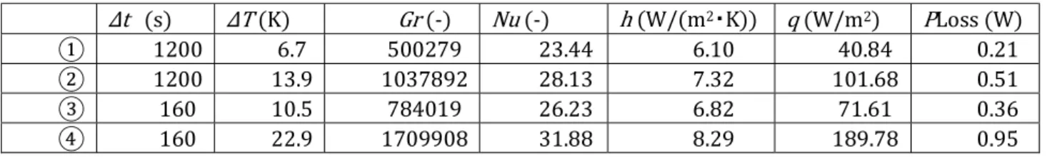
Δt (s) ΔT (K) Gr (-) Nu (-) h (W/(m2・K)) q (W/m2) PLoss (W) ① 1200 6.7 500279 23.44 6.10 40.84 0.21 ② 1200 13.9 1037892 28.13 7.32 101.68 0.51 ③ 160 10.5 784019 26.23 6.82 71.61 0.36 ④ 160 22.9 1709908 31.88 8.29 189.78 0.95
Table 3.4 Heat loss from barrel side wall and bottom
Δt (s) ΔT (K) q (W/m2) PLoss (W) ① 1200 6.7 0.001117 0.0000335 ② 1200 13.9 0.002317 0.0000695 ③ 160 10.5 0.013125 0.00039375 ④ 160 22.9 0.028625 0.00085875
Table 3.3 shows that the heat loss from the vessel is very small, bellow 3% of ultrasound power, and thus the heat loss can be ignored in the present measurements.
3.2. Weissler reaction
In this study, Weissler reaction was employed to evaluate the formation rate of OH radicals. Weissler reaction has been widely used as a test reaction to investigate ultrasonic and hydrodynamic cavitation. The OH radicals, which generated in cavitation zone have a very short lifetime and react soon with iodide ion through a series of intermediate steps, to form tri-iodide complex I3-. The key reactions are assumed to be as follows [91]:
35
OH ∙ +I → OH + I (3-11)
I + I → I (3-12)
I → I + 2I (3-13)
I + I → I (3-14)
Concentration of tri-iodide complex I3- was measured by the above mentioned ultraviolet
visual spectrophotometer (Shimadzu Co., Ltd, Japan) based on the maximum absorption peak of I3- at a wavelength for 353nm. Then, the rate of I3- ion formation was determined and used
as a quantitative measurement of OH radical generation. As can be readily seen from the above reactions, two OH radicals must react with two I- ions to produce one I3- ion. Therefore, the
rate of OH radical formation can be obtained simply by multiplying the rate of I3- ion formation
by 2. During the irradiation process, the higher KI concentration yields a higher OH generation rate. However, the addition of KI will increase the surface tension and ionic strength of solution, and also decrease the vapor pressure, which affects the yield of OH radicals. Thus, 0.1 mol/L was applied as a proper concentration to estimate the radical generation rate in this research.
3.3 Radical generation with various parameters
3.3.1 Effect of power change during ultrasound irradiation in circulatory reactor
In the circulatory reactor, at least 6 L KI solution is needed for operation. In order to reduce waste solution discharge and investigate the effect of ultrasound power on the OH radical generation, the power was changed in the course of experiments. Figure 3.2 shows a typical result when power was changed from 4 W to 24 W.
36
Figure 3.2 Effects of power changing on I3- concentration increase (4 →24 W)
When the output power is 4 W, the concentration of tri-iodide ion shows a linear rise. However, the concentration rise tends to decrease at an output power of 7 W. This may be explained by occurrence of following reactions:
2OH・ → H O (3-15)
H O + I → 3I + O + 2H (3-16)
Figure 3.3 shows the effects of power changes on I3- concentration. During the first period
with 24 W irradiation, the I3- concentration increased. However, after that when lower power
37
Figure 3.3 Effects of power changing on I3- concentration increment (24 →4 W)
These results suggest that other reactions than the Weissler reaction may occur under the present experimental conditions
3.3.2 Effects of flow rate in circulatory reactor
Figure 3.4 shows the effects of flow rate on I3- concentration in circulatory reactor without
ultrasound irradiation. It is seen that although there is no ultrasound irradiation and thus there is not origin of the OH radical generation, I3- concentration is steadily increased with time.
Concentration of I3- at 2 and 4 L/min shows almost the same growth, while that at 6 L/min rises
much slowly. Such an effect can be explained by oxidation with air. In addition, the cooling coil of circulator is made of Cu-Ni alloy, and the reaction between Cu and I- may be another reason which results in the increase of the I3- concentration as shown below:
Cu2+ + 2I- → CuI
2 (3-17)
2CuI
2→ 2CuI + I
2 (3-18)38
Figure 3.4 Effects of flow rate on I3- concentration increment without ultrasound irradiation
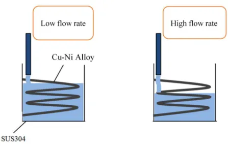
As shown in Figure 3.5, compared to low flow rate condition, high flow rate results in lowering the solution level in the circulator because a larger amount of solution is pumped into the reactor. Therefore, the contact area of KI solution and cooling coil becomes smaller resulting in a slower I3- concentration increment. However, this assumption should be verified
by further investigation.
Figure 3.5 Schematic of solution level in circulator with various flow rate
Thus, taking into account the above findings, in order to determine the correct time variation of I3- concentration during the ultrasound irradiation, one has to subtract the values of
39
I3- concentrations shown in Figure 3.4 from the measurement results. Figure 3.6 shows the true
effects of flow rate on I3- concentration with the ultrasound irradiation at 12 W. After 2 hours
ultrasound irradiation, the increment of I3- showed a slight increase, and no significant
difference can be seen with various flow rates.
Figure 3.6 Effects of flow rate on I3- concentration with ultrasound irradiation at 12 W
The effects of flow rate on I3- concentration in 137 and 301 W were investigated using
device B, and the results are shown in Figure 3.7 and 3.8 respectively. At the 137 W ultrasound irradiation, the highest I3- concentration increment was observed at 4 L/min flow rate. At the
other flow rates, 2 and 6 L/min, the increment is almost the same. A possible explanation of these results may be that 4 L/min flow rate yields a flow which is well balanced with acoustic streaming and produces a well-agitated flow field in the reactor. The further investigation on this issue will be discussed in part 3.4 using results of numerical simulation. In general, the I3-
concentration increment at 137 W ultrasound irradiation is significantly higher than that at 12 W ultrasound irradiation.
In the case of 301W ultrasound irradiation, the I3- concentration increments are also
40
various flow rates is observed. This is because at high ultrasound power the water flow in the reactor is controlled mainly by strong acoustic streaming.
Figure 3.7 Effects of flow rate on I3- concentration with ultrasound irradiation at 137 W
Figure 3.8 Effects of flow rate on I3- concentration with ultrasound irradiation at 137 W
3.3.3 Effects of output power in batch reactor
In batch type reactor, effects of output power on I3- concentration were also investigated.
The I3- generation rate is showed in Figure 3.9 as a function of ultrasound irradiation power.
The generation rate of I3- shows a significant growth with increasing the ultrasound power,
41
Figure 3.9 Effects of flow rate on I3- concentration with ultrasound irradiation at 137 W
With the increasing of ultrasound power, cavitation intensity at the zone near sonotrode surface also increases. On the other hand, high cavitation intensity would cause larger energy loss of ultrasound when propagating through the bubble-containing cavitation zone. As a result, high ultrasound power produces a high-intense but short cavitation zone, as shown in Figure 3.10. Therefore, the generation rate of I3- can be slowed down in the high ultrasound power
conditions
Figure 3.10 Schematic representation of cavitation zone change at various ultrasound powers
3.3.4 Effects of ultrasound power in circulatory reactor
Figure 3.11 shows the effect of ultrasound power on I3- generation in the circulatory
reactor. In the ultrasound power range from 0 ~ 137 W, I3- generation rate shows significant
growths with power at all flow rates, with the highest generation rate obtained at the 4 L/min flow rate. However, the generation rate at 2 and 4 L/min decreased when ultrasound power is higher than 137W, while that at 6 L/min remains almost constant.
42
Figure 3.11 Effects of ultrasound power on I3- generation in circulatory reactor
These results can be explained as follows. Two main macro flows, acoustic streaming and pumped flow, exist in the circulatory reactor, which affects significantly the mass transfer in the reactor. Probably, at the condition of high ultrasound power, acoustic streaming and pumped flow results in an insufficient agitation of water in the reactor, which may inhibit the I3
-generation. This point will be discussed using results of numerical simulation in the next part. In addition, at the 6 L/min flow rate, I3- generation rate remains almost constant probably
because the pumped flow affects the flow pattern and mass transfer in the reactor to a greater extent as compared to the acoustic streaming.
3.4 Numerical simulation on cavitation zone and acoustic streaming
In part 3.3, effects of ultrasound power and flow rate on I3- generation were investigated.To further investigate the effects of acoustic streaming, numerical simulation was performed in this part.
A simplified model was developed to predict the size of cavitation zone and pattern of acoustic streaming under the sonotrode tip area. The main simplifications and assumptions of the model can be formulated as follows