Remote Control of a Networked Mobile Robot using an Immersive Locomotion Interface
4
0
0
全文
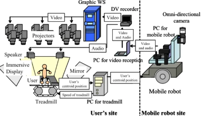
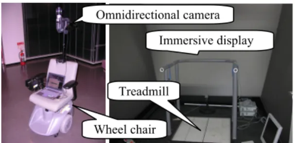
(2) DV recorder It receives the stream, sends the video to Graphics WS, and outputs the audio to the speakers.. Omnidirectional camera Immersive display. Treadmill Wheel chair. Fig. 2. Appearance of mobile robot (left), immersive display, and treadmill (right). Omni-directional camera (HyperOmni Vision) The omni-directional camera is mounted on the mobile robot so that it is located at almost the same height (about 160cm) as user’s viewpoint. The omni-directional camera acquires a 360-degree view around the robot. The omnidirectional camera satisfies the single viewpoint constraint and thus the acquired omni-directional video can be transformed to common perspective video as well as panorama video suitable for presentation[9]. PC for mobile robot (SONY: PCG-R505FR-D) It is carried on the mobile robot, and controls the robot based on user’s walking information which is received via network. Simultaneously, it transports the acquired omnidirectional video and audio to the user’s site via network. Treadmill (SOLIDRAY: WalkMaster) The belt of the treadmill can be moved into all directions on a 2D plane. Therefore, the user can walk in all directions on the 2D plane. The user wears the magnetic sensors on both knees. The belt is moved so that the centroid of both knees is kept at the center of the treadmill. The user can walk at the fixed point on the treadmill [10]. The position of the centroid is used not only for controlling the treadmill but also for controlling the mobile robot by transporting the position of the centroid via network. PC for treadmill It controls the treadmill based on information from the magnetic sensor. Simultaneously, it transports user’s waking information to the mobile robot site. Immersive display (SOLIDRAY: VisualValley) It consists of three large slanted screens (see Fig. 2 (right)) and corresponding twelve projectors (four projectors per screen). It displays video transported from the mobile robot. Graphics WS (SGI: ONYX3800) It transforms omni-directional video to common perspective video for the immersive display. PC for video reception It receives the stream which includes video and audio via network and sends the stream to the DV recorder.. 2.2. Network transmission The system has two network transmissions. One is videoand-audio stream transmission. The other is operation instruction transmission. In video-and-audio stream transmission, the mobile robot site is the sender and the user’s site is the receiver. On the other hand, in operation instruction transmission, the user’s site is the sender and the mobile robot site is the receiver. For transporting omni-directional video, we use DVcommXP software made by Fatware Co. DVcommXP is based on RTP Payload Format for DV Video (RFC 3189) [11]. DVcommXP can transport high-resolution DV data (720x480, 30fps) using 30Mbps bandwidth via network. In this study, we set the framerate to 10fps for bandwidth of wireless network. The mobile robot site sends the omnidirectional video from the omni-directional camera mounted on the mobile robot. The user’s site receives the omnidirectional video and transfers the video to the graphic WS via the DV recorder. The graphic WS transforms omnidirectional video to common perspective video and projects it on the immersive display. The user’s walking action is estimated by using magnetic sensors worn on both knees. Walking information is then transported to the PC on the mobile robot by using TCP/IP. At the mobile robot site, the PC transforms the received walking action to adequate instructions for the mobile robot and controls the mobile robot. The mobile robot can move only forward-and-backward and can rotate right-and-left as mentioned earlier. Therefore, the user’s forward-and-backward translation and right-and-left translation should be reflected to forward-and-backward translation and right-and-left rotation of the mobile robot. 2.3. Video presentation The transformed video is presented on the immersive display. First, the graphic WS transforms the omnidirectional video transported from the mobile robot via network to twelve common perspective videos corresponding to the number of projectors in real-time using an image warping technique [12]. Next, each common perspective video is presented on the immersive display via the associated projector. Moreover, for presenting a backward scene of the mobile robot, its common perspective video is generated and is presented on the upper part of the front screen as a rearview (see Fig. 3(b)).. 2118.
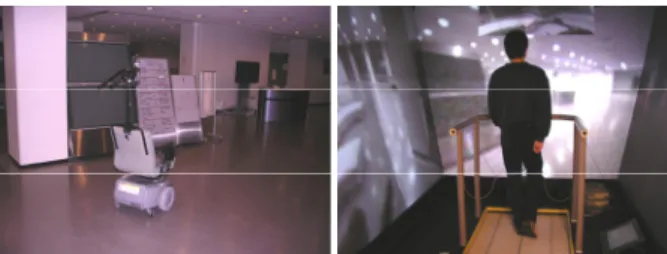
(3) Fig. 4. Appearance of mobile robot site (left) and user’s site (right) in experiment.. (a) Omni-directional image.. (b) Common perspective images for three screens. Fig. 3. Omni-directional image and corresponding common perspective images projected on three screens. 3. EXPERIMENTS 3.1. Overview of experiments We have experimented with the prototype system. The user’s and mobile robot sites are located in different buildings. The distance between both sites is about 200m. The user wears magnetic sensors on both of knees, watches the video capturing the mobile robot site, and controls the mobile robot using the proposed locomotion interface. The network between both buildings is a wired 100Mbps connection. The network between the building and mobile robot is a wireless 54Mbps connection. We have set the framerate of video to 10 frames/sec. adjusting DVcommXP and have set the maximum speed of mobile robot to 2 km/h. Fig.4 shows the appearance of experimental environments. We have confirmed that the user can control the remote mobile robot by walking. The time delay from acquiring an omni-directional image to presenting it on the screen via network is about 1 second. The time delay from the beginning of user’s walking to the beginning of the movement of mobile robot is also about 1 second. The delay is mainly caused by network delay. In the present implementation, the user must consider the delay of at most 2 seconds. Evaluation of the prototype system is described in the following section. 3.2. Evaluation of usability 3.2.1. Tasks for evaluating usability For evaluating the usability, we have defined the following three tasks. Subjects know the size and moving mechanism of the remote robot before the tasks. Subjects control the mobile robot for tasks and some quantitative evaluation is carried out. Task 1: Stopping in front of an obstacle The mobile robot approaches an obstacle as close as possible and stops in no contact. The robot moves only straight forward. The distance between the starting point. and the obstacle is 4.25m. The purpose of this task is to examine how much the delay affects the operation requiring the sense of distance. Task 2: Moving to a target point The mobile robot moves to a target point that the mobile robot cannot reach only by moving forward from the initial state of position and orientation. There is no obstacle in this task. When the task starts, the user can see the target point via the immersive display. The user can control the mobile robot within his/her discretion. The distance between the starting point and the target point is 5.60m. The user needs to move forward, rotating when the target point is not ahead of the mobile robot. The purpose of this task is to evaluate the intuitiveness of correspondence between user’s movement and mobile robot movement. Task 3: Avoiding obstacles and moving to a target point The mobile robot avoids obstacles and moves to a target point. The distance in a straight line between the starting point and the target point is 6.70m. It is required to control the mobile robot without a collision with obstacles. The robot is required a rather long movement for avoiding obstacles. When the task starts, the user can see the target point via the immersive display. The purpose of this task is to evaluate the total maneuverability of the system. The number of subjects for each task is nine. All of the subjects are beginners for using the system. 3.2.2. Results and discussion Table 1 shows the results of task 1 including the operation time and the distance from the stopping point to the obstacle. The negative value means the distance between the obstacle and the stopping point after collision. The robot moves about 1m in the total time delay of 2 seconds when it runs at 2km/h. The results are within 1m. The subjects who are required much time can control the robot close to the obstacle. It should be noted that subjects are required to pay attention to the time delay when the distance between the robot and the obstacle is less than the distance to which the robot moves in the time delay. Fig. 5 shows the results of task 2 including the operation time and the trajectory of the mobile robot. Few subjects changed the direction of the robot to the target point at first and moved straight forward. Many other subjects moved and rotated to the target point simultaneously. Since the distance between the starting point and the target point is large enough, the subjects could. 2119.
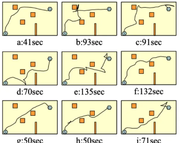
(4) Table 1. Results of task1: Operation time and distance between stopping point and obstacle. Operator a b c d e f g h i Operation time (sec.) 14 16 12 22 17 12 13 Distance (cm). between the robot and obstacles, and (iv) the time delay is long. 4. CONCLUSION. 22 15. 1 -35 40 -5 70 35 100 -10 10. adjust the direction of the robot to the target point repeatedly. It is confirmed that subjects can control the robot intuitively corresponding subjects’ movement and the mobile robot movement when the subjects do not need to pay attention to obstacles. Fig. 6 shows the results of task 3 including the operation time and the trajectory of the mobile robot. In this task, the skill of controlling the robot correctly for avoiding obstacles is required. Some subjects are required much time for the task. We observed that the reasons for this were either the speed is reduced for controlling the robot, or changing direction is repeated for avoiding the obstacles. Many subjects have reported that the task is difficult due to the followings: (i) there is no sense other than vision from the environment around the robot, (ii) the resolution of presented video is low, (iii) it is difficult to feel the distance. G. G. S. G. S. a:18sec. S. b:35sec G. c:42sec G. S. G. S. d:19sec. S. f:21sec. e:22sec G. G. S. G. S. S. g:26sec h:26sec i:23sec Fig. 5 Results of task 2: Operation time and trajectory. G. S. G. S. a:41sec. S. b:93sec G. S. c:91sec G. G. S. S. d:70sec. f:132sec. e:135sec G. S. G. G. S. G. S. g:50sec h:50sec i:71sec Fig. 6 Results of task 3: Operation time and trajectory.. We have constructed a remote control system for a mobile robot with a locomotion interface and an immersive display. The usability of the system has been evaluated with experiments. Future work includes the followings. For the time delay, the graphics WS will show the estimated present location of the mobile robot on the immersive screen by drawing CG of the robot. The mobile robot should be equipped with obstacle detecting sensors. When the sensor detects a close obstacle, the mobile robot and the treadmill should stop for feedback to a user. 5. REFERENCES [1] D. G. Caldwell, A. Wardle, and M. Goodwin, “Tele-presence: visual, audio and tactile feedback and control of a twin armed mobile robot,” Proc. IEEE Int. Conf. on Robotics and Automation, Vol. 1, pp. 244-249, 1994. [2] I. Elhajj, N. Xi, and Y. Liu, “Real-time control of internet based teleoperation with force reflection,” Proc. Int. Conf. on IEEE Robotics and Automation, vol. 4, pp. 3284-3289, 2000. [3] P. Jensfelt and S. Kristensen, “Active global localization for a mobile robot using multiple hypothesis tracking,” IEEE Trans. on Robotics and Automation, vol. 17, pp. 748-760, 2001. [4] D. A. Bell, J. Borenstein, S. P. Levine, Y. Koren, and J. Jaros, “An assistive navigation system for wheelchairs based upon mobile robot obstacle avoidance,” Proc. IEEE Int. Conf. on Robotics and Automation, vol. 3, pp. 2018-2022, 1994. [5] D. Schulz, W. Burgard, D. Fox, S. Thrun, and A.B. Creemers, “Web interfaces for mobile robots in public places,” IEEE Robotics and Automation Magazine, Vol. 7, No. 1, pp. 48-56, 2000. [6] H. Hirukawa, T. Matsui, H. Onda, K. Takase, Y. Ishiwata, and K. Konaka, “Prototypes of teleoperation systems via a standard protocol with astandard human interface,” Proc. IEEE Int. Conf. on Robotics and Automation, Vol. 2, pp. 1028-1033, 1997. [7]. N. Yokoya, K. Yamazawa, and H. Takemura, “Interactive media-oriented applications of an omnidirectional video camera,” Proc. World Automation Congress, Vol.13, pp.11-16, 2002. [8]. R. Kurazume and S. Hirose, “Development of image stabilization system for remote operation of walking robots,” Proc. IEEE Int. Conf. on Robotics and Automation, Vol.2, pp.1856-1861, 2000. [9]. K. Yamazawa, Y. Yagi, and M. Yachida, “Omnidirectional imaging with hyperboloidal projection,” Proc. Int. Conf. on Intelligent Robots and Systems, Vol.2, pp.1029-1034, 1993. [10] H. Iwata, “Walking about virtual environments on an infinite floor,” Proc. IEEE Virtual Reality, pp.286-293, 1999. [11]. K. Kobayashi, A. Ogawa, S. L. Casner, and C. Bormann, “RTP payload format for DV (IEC 61834) video,” Internet Requests For Comments, RFC 3189, 2002. [12]. Y. Onoe, K. Yamazawa, H. Takemura, and N. Yokoya, “Telepresence by real-time view-dependent image generation from omnidirectional video streams,” Computer Vision and Image Understanding, Vol.71, No.2, pp.154-165, 1998.. 2120.
(5)
図
関連したドキュメント
initial functions are proved in the form of an integral maximum principle and conditions of transversality for nonlinear systems with a variable structure, delays and a
Standard domino tableaux have already been considered by many authors [33], [6], [34], [8], [1], but, to the best of our knowledge, the expression of the
If Φ is a small class of weights we can define, as we did for J -Colim, a2-category Φ- Colim of small categories with chosen Φ-colimits, functors preserving these strictly, and
Eskandani, “Stability of a mixed additive and cubic functional equation in quasi- Banach spaces,” Journal of Mathematical Analysis and Applications, vol.. Eshaghi Gordji, “Stability
An easy-to-use procedure is presented for improving the ε-constraint method for computing the efficient frontier of the portfolio selection problem endowed with additional cardinality
Let X be a smooth projective variety defined over an algebraically closed field k of positive characteristic.. By our assumption the image of f contains
[11] Karsai J., On the asymptotic behaviour of solution of second order linear differential equations with small damping, Acta Math. 61
Applications of msets in Logic Programming languages is found to over- come “computational inefficiency” inherent in otherwise situation, especially in solving a sweep of
