九州大学学術情報リポジトリ
Kyushu University Institutional Repository
Deformation-induced ε-martensitic
transformation effect and fatigue crack growth mechanism on the low cycle fatigue in high-Mn austenitic alloys
ジュ, ユンバン
https://doi.org/10.15017/1866294
出版情報:九州大学, 2017, 博士(工学), 課程博士 バージョン:
権利関係:
i
Deformation-induced ε-martensitic transformation effect and fatigue crack growth mechanism on the low cycle fatigue in high-Mn austenitic alloys
A dissertation submitted to the faculty of engineering
Graduate school, Kyushu University, Japan
For the degree of doctor of philosophy
Presented by Yun-Byum JU
May 2017
ii
Contents
CHAPTER 1. GENERAL INTRODUCTION ... 1
1.1 Background of this study... 1
1.2 Outline of this study ... 5
References ... 7
CHAPTER 2. Macroscopic observation of low cycle fatigue crack growth behavior associated with deformation-induced ε-martensitic transformation in high-Mn austenitic alloys ... 14
2.1 Introduction ... 14
2.2 Experimental procedures ... 16
2.3 Results... 18
2.3.1 Fatigue crack growth rate ... 18
2.3.2 Fatigue crack growth behavior ... 18
2.3.3 Microstructural features at the crack tips ... 22
2.3.4 Crack opening and closing processes during one cycle ... 23
2.4 Discussion ... 24
2.4.1 Crack propagation path along the {111}γ planes; similar behaviors produced by different underlying mechanisms ... 24
2.4.2 Effects of subcracks: coalescence and crack toughening ... 29
2.4.3 Factors affecting fatigue crack growth: why does the Fe-30Mn-4Si-2Al alloy show the outstanding fatigue resistance? ... 30
2.5 Conclusions ... 33
References ... 35
CHAPTER 3. Effects of ε-martensitic transformation on crack tip deformation, plastic damage accumulation, and slip plane cracking associated with low cycle fatigue crack growth ... 50
3.1 Introduction ... 50
iii
3.2 Experimental procedures ... 52
3.3 Results... 53
3.3.1 Fracture surface observation pertaining to short and long fatigue crack growth ... 53
3.3.2 EBSD measurements at the vicinities of fracture surfaces ... 54
3.4 Discussion ... 57
3.4.1 Correlation between strain localization and crack growth, and its crack length dependence: the chemical composition effects on fatigue behavior ... 57
3.4.2 Contribution of ε-martensitic transformation in deceleration of fatigue crack growth: from the viewpoint of crack tip deformation ... 60
3.5 Conclusions ... 66
References ... 68
CHAPTER 4. Microscopic observation of low-cycle fatigue crack propagation for investigation of fatigue crack growth mechanism ... 87
4.1 Introduction ... 87
4.2 Experimental procedure ... 89
4.3 Experimental results ... 90
4.3.1 Fatigue crack growth rate ... 90
4.3.2 In-situ SEM observation during one cycle in the Fe-30Mn-4Si-2Al alloy ... 90
4.3.3 In-situ SEM observation during one cycle in the Fe-30Mn-6Si alloy ... 91
4.4 Discussion ... 93
4.5 Conclusion ... 96
References ... 98
CHAPTER 5. GENERAL CONCLUSION ... 109
Acknowledgement... 112
1
CHAPTER 1. GENERAL INTRODUCTION
1.1 Background of this study
In many industries, technology has been developed and companies have applied the new technology. In past, many companies focused on high performance of their product such as high speed car with high displacement volume. However, increasing environmental regulation, competition of high fuel efficiency and made automobile companies to reduce the weight of their products. And the trend of weight reduction has spread out into other industries and has lasted until now because of a benefit to decrease an entry cost of their products. On the other hand, many automobile companies have also made a lot of efforts in development of new materials to satisfy increasing crash worthiness as shown in Fig. 1.1. The high-Mn austenitic steels have been considered as structural applications in automotive industry [1].
Numerous studies have been performed on high-Mn austenitic steels because of their high strength and ductility. The excellent mechanical properties of high-Mn steels arise from either transformation-induced plasticity (TRIP) or twinning-induced plasticity (TWIP) effects [2, 3]. The dominant plastic deformation mechanism is dependent upon a variety of factors, including the chemical composition and temperature [2, 4-6]. It has been reported that the stacking fault energy (SFE), which depends upon the chemical composition and temperature, controls the plastic deformation mechanisms in high-Mn austenitic steels [4, 5]. Fig. 1.2 shows the volume fraction changes of ε-martensitic transformation in high-Mn austenitic alloys [7]. In the Fe-30Mn-Al-Si alloys, when the Si component increased, the volume
2
fraction of ε-martensitic transformation also increased as shown in Fig. 1.2 (g) and (k). In addition, it has been also reported that the SFE of the Fe-30Mn-3Al-3Si and Fe-30Mn-6Si alloys are 7.8 mJ/m2 and 40 mJ/m2, respectively [8, 9]. Therefore, the addition of Al and Si (i.e., solute elements) has been used to control the SFE to obtain the desired TRIP and TWIP effects [2, 10]. The plastic deformation mode of high-Mn austenitic alloys depends on the SFE. The ε-martensitic transformation and mechanical twinning are reported to occur in high-Mn alloys, which have the SFE below 18-20 mJ/m2 and between 15-45 mJ/m2, respectively [11, 12]. When the SFE is higher than 45 mJ/m2, the dominant plastic deformation become dislocation cross- slip [13]. For example, when the SFE is extremely low, e.g., in Fe-30Mn-6Si and Fe- 30Mn-4Si-2Al alloys, remarkable ε-martensitic transformation occurs, which result in TRIP effects [10].
Recently, the austenitic TRIP steels that are associated with ε-martensite have received much attention as potential damping materials for buildings because of their superior low-cycle fatigue properties [6, 7, 14]. In previous study, fatigue tests of the Fe-30Mn-xSi-(6-x)Al alloys (x=0~6) were conducted to investigate the fatigue properties as shown in Table 1.1 [6]. And the Fe-30Mn-4Si-2Al alloy has a fatigue life that is more than four times longer than that of conventional austenitic steels, such as TWIP and stainless steels [6]. To clarify the importance of ε-martensitic transformation, the fatigue lives of various high-Mn austenitic steels with different γ/ε phase stabilities have been compared [6]. The results of this comparative study indicated that deformation-induced, reversible, γ ↔ ε martensitic transformation plays a crucial role in improving the fatigue life [15, 16]. However, the relationship
3
between the low cycle fatigue resistance and effect of ε-martensitic transformation in the Fe-30Mn-4Si-2Al alloy still has remained unclear. Moreover, the fatigue crack growth mechanism of the Fe-30Mn-4Si-2Al alloy has not uncovered.
The fatigue life is composed of the crack initiation period and crack propagation period [17]. The crack initiation life is used in the fatigue life prediction method called ‘safe-life’. In the safe-life design based on the prediction of fatigue crack nucleation, a large margin should be selected to avoid unexpected fails, which can be caused by many factors such as scatter in experiment results and error in expected service load, etc. [18]. And the large margin contributes to the increase in the weight and production cost. For these reason, some industries such as a nuclear power plant, airplane, and etc. that demand a high entry cost and long operating time have used the crack propagation life for the fatigue life prediction. In addition, high-Mn austenitic steels showed short the crack initiation life compared to the crack propagation life in low cycle fatigue. For example, a fatigue crack in the Fe-30Mn- 4Si-2Al alloy was initiated at 200 cycles and at a total strain range of 2%, even though the total fatigue life was longer than 11,000 cycles [19]. Therefore, when high-Mn austenitic steels are considered as structural materials in not only these industries but also automobile companies, the study of fatigue crack propagation behavior in high-Mn austenitic steels is important for effective design.
In present study, the Fe-30Mn-6Al, Fe-30Mn-4Si-2Al alloy and Fe-30Mn-6Si alloys were used. The chemical composition and results of tensile test are shown in Table 1.2 and Fig. 1.3 [20]. The SFE and associated plastic deformation mode of three alloys are summarized in Table 1.3 [8-13]. The Fe-30Mn-4Si-2Al alloy, which
4
showed low cycle fatigue resistance, was used to investigate the fatigue crack growth mechanism. In addition, the Fe-30Mn-6Al and Fe-30Mn-6Si alloys, which have slip deformation and ε-martensitic transformation as a dominant plastic deformation mode respectively, were used to compare the effect of ε-martensitic transformation in low cycle fatigue. More specifically, the Fe-30Mn-6Al and Fe-30Mn-4Si-2Al alloys have same initial microstructure and different plastic deformation mode. Therefore, the effect of ε-martensitic transformation on the fatigue crack growth behavior can be compared during low cycle fatigue. The Fe-30Mn-4Si-2Al and Fe-30Mn-6Si alloys have same plastic deformation mode. However, only the Fe-30Mn-6Si alloy shows pre-existing ε-martensite before fatigue test. Therefore, the effects of pre- existing ε-martensite and volume fraction of ε-martensite can be compared.
5
1.2 Outline of this study
The main theme of this thesis is the investigations of fatigue crack growth mechanisms in high-Mn-austenitic alloys during low-cycle fatigue. The Fe-30Mn- 6Al, Fe-30Mn-4Si-2Al and Fe-30Mn-6Si alloys that showed conventional slip deformation, strong low cycle fatigue resistance and highest volume fraction of ε- martensite respectively were used to compare the crack growth mechanisms.
Chapter 1. General introduction of this study was described with research background and outline of this thesis.
Chapter 2. The microstructural changes and macroscopic fatigue crack growth behavior in Fe-30Mn-6Al, Fe-30Mn-4Si-2Al, and Fe-30Mn-6Si alloys were observed in situ by optical microscopy. The results indicate that ε-martensitic transformation in the Fe-30Mn-4Si-2Al alloy has three positive effects on crack growth: Ⅰ) the suppression of strain localization; Ⅱ) zigzag crack propagation, which enhances roughness-induced crack closure; and Ⅲ) subcrack formation, which induced crack toughening, such as stress redistribution. On the other hand, the ε- martensite has a negative effect on crack growth, i.e., it causes subcrack initiation, which leads to the subcrack coalescence with the main crack. However, the ε- martensitic transformation in the Fe-30Mn-4Si-2Al alloy is optimized so that the positive effects are maximized and the negative effect is minimized, which results in the superior resistance of the alloy against low-cycle fatigue.
6
Chapter 3. In order to examine ε-martensitic transformation effect on localization of plastic strain, plastic strain evolutions in the vicinity of crack path were investigated at different crack lengths in Fe-30Mn-6Al, Fe-30Mn-4Si-2Al, and Fe-30Mn-6Si alloys. Specifically, fractographic analyses and electron backscatter diffraction measurements underneath the fracture surfaces were carried out. In terms of crack tip deformation, the key roles of ε-martensitic transformation are (1) brittle-like cracking along γ/ε interface, (2) inhibition of fatigue damage accumulation, and (3) geometrical constraint of ε-martensite crystallographic structure at a fatigue crack tip.
Because of the roles (2) and (3) above, the Fe-30Mn-4Si-2Al alloy showed the lowest fatigue crack growth compared to the other tested alloys. This chapter presents the proposed ε-martensite-related crack growth mechanism in details.
Chapter 4. In order to examine the mechanisms proposed in chapter 2, microscopic fatigue crack growth behaviors of the Fe-30Mn-4Si-2Al and Fe-30Mn-6Si alloys were investigated by in situ SEM observation during one cycle. The results indicate that the Fe-30Mn-6Si alloy has subcrack initiation and cracking behavior caused by pre-existing ε-martensite as a dominant crack growth behavior. The fatigue crack growth rate of the Fe-30Mn-4Si-2Al alloy is delayed due to positive effects of ε- martensitic transformation and annealing twin boundary. The suppression of plastic deformation localization by reverse transformation of ε-martensite and decrease of driving force at a crack tip contributed to low cycle fatigue resistance in the Fe- 30Mn-4Si-2Al alloy.
Chapter 5. General conclusion of the each chapters by present studies are summarized.
7
References
[1] O. Bouaziz, S. Allain, C.P. Scott, P. Cugy, D. Barbier, High manganese austenitic twinning induced plasticity steels: A review of the microstructure properties relationships, Curr. Opin. Solid. State. Mater. Sci. 15 (2011) 141-168.
[2] O. Grässel, L. Krüger, G. Frommeyer, L.W. Meyer, High strength Fe-Mn- (Al, Si) TRIP/TWIP steels development d properties d application, Int. J. Plast. 16 (2000) 1391-1409.
[3] Y.K. Lee, Microstructural evolution during plastic deformation of twinning- induced plasticity steels, Scr. Mater. 66 (2012) 1002-1006.
[4] L. Remy, A. Pineau, Twinning and strain-induced F.C.C. → H.C.P.
transformation in the Fe-Mn-Cr-C system, Mater. Sci. Eng. 28 (1977) 99-107.
[5] S. Allain, J.-P. Chateau, O. Bouaziz, S. Migot, N. Guelton, Correlations between the calculated stacking fault energy and the plasticity mechanisms in Fe- Mn-C alloys, Mater. Sci. Eng. A 387 (2004) 158-162.
[6] I. Nikulin, T. Sawaguchi, K. Tsuzaki, Effect of alloying composition on low-cycle fatigue properties and microstructure of Fe-30Mn-(6-x)Si-xAl TRIP/TWIP alloys, Mater. Sci. Eng. A 587 (2013) 192-200.
[7] T. Sawaguchi, I. Nikulin, K. Ogawa, K. Sekido, S. Takamori, T. Maruyama, Y. Chiba, A. Kushibe, Y. Inoue, K. Tsuzaki, Designing Fe-Mn-Si alloys with improved low-cycle fatigue lives, Scr. Mater. 99 (2015) 49-52.
[8] J. Xuejun, Z. Jihua, T.Y. Hsu, Mater. Des. 21 (2000) 537-539.
[9] S. Vercammen, B. Blanpain, B.C. de Cooman, P. wollants, Acta Mater. 52
8
(2004) 2005-2012.
[10] K. Ogawa, T. Sawaguchi, T. Kikuchi, M. Koyama, M. Murakami, Influence of Al concentration on deformation behavior and fracture mode of fe-30Mn-6(Si, Al) alloys, in: International Conference on Shape Memory and Superelastic Technologies, SMST-2007, 2008.
[11] H.-G. Lambers, C.J. Rusing, T. Niendorf, D. Geissler, J. Freudenberger, H.J.
Maier, Int. J. Fat. 40 (2012) 51-60.
[12] Y.F. Shen, C.H. Qiu, L. Wang, X. Sun, X.M. Zhao, L. Zuo, Mater. Sci. Eng.
A 561 (2013) 329-337.
[13] M. Iker, D. Gaude-Fugarolas, P.J. Jacques, F. Delannay, Adv. Mater. Res.
15-17 (2007) 852-857.
[14] H. Li, M. Koyama, T. Sawaguchi, K. Tsuzaki, H. Noguchi, Importance of crack propagation-induced ε-martensite in strain-controlled low-cycle fatigue of high-Mn austenitic steel, Phill. Mag. Lett. 95 (2015) 303-311.
[15] T. Sawaguchi, P. Sahu, T. Kikuchi, K. Ogawa, S. Kajiwara, A. Kushibe, M.
Higashino, T. Ogawa, Vibration mitigation by the reversible fcc/hcp martensitic transformation during cyclic tension-compression loading of an Fe-Mn-Si-based shape memory alloy, Scr. Mater. 54 (2006) 1885-1890.
[16] T. Sawaguchi, L.G. Bujoreanu, T. Kikuchi, K. Ogawa, M. Koyama, M.
Murakami, Mechanism of reversible transformation-induced plasticity of Fe-Mn- Si shape memory alloys, Scr. Mater. 59 (2008) 826-829.
[17] J. Schijve, Fatigue of Structures and Materials, Springer, 2009 [18] S. Suresh, Fatigue of Materials, Cambridge, 1998
[19] H. Li, M. Koyama, T. Sawaguchi, K. Tsuzaki, H. Noguchi, Importance of
9
crack propagation-induced ε-martensite in strain-controlled low-cycle fatigue of high-Mn austenitic steel, Phill. Mag. Lett. 95 (2015) 303-311
[20] K. Yamada, M. Koyama, T. Kaneko, K. Tsuzaki, Positive and negative effects of hydrogen on tensile behavior in polycrystalline Fe-30Mn-(6-x)Si-xAl austenitic alloys, Scr. Mater. 105 (2015) 54-57.
10
Table 1.1 LCF life, Nf, Young’s modulus, E, and monotonic tensile properties [6].
Material Nf (cycles) E (GPa) σ0.2 (MPa) σUTS (MPa) n δ (%)
Fe-30Mn-6Al-0Si 750 156 214 479 0.21 54
Fe-30Mn-5Al-1Si 770 163 228 492 0.20 56
Fe-30Mn-4Al-2Si 1790 171 238 507 0.19 65
Fe-30Mn-3Al-3Si 2112 174 260 574 0.19 72
Fe-30Mn-2Al-4Si 8070 179 290 634 0.18 64
Fe-30Mn-1Al-5Si 2080 174 248 690 0.26 57
Fe-30Mn-0Al-6Si 2024 150 218 745 0.28 30
Table 1.2 Chemical compositions of the alloys used (wt.%) [20].
Alloys Mn Al Si Fe
Fe-30Mn-6Al 30.1 5.75 0 Bal.
Fe-30Mn-4Si-2Al 29.99 1.98 4.06 Bal.
Fe-30Mn-6Si 30.08 0.004 6.08 Bal.
11
Table 1.3 SFE and associated plastic deformation mode by chemical composition of Al and Si [8, 9, 11-13].
Alloys SFE γ stability Plastic deformation mode
Fe-30Mn-6Al-0Si γ stable Slip deformation
Fe-30Mn-5Al-4Si Fe-30Mn-4Al-2Si
Fe-30Mn-3Al-3Si 40 mJ/m2 Twinning deformation
Fe-30Mn-2Al-4Si Twinning / ε-martensitic transformation
Fe-30Mn-1Al-5Si
Fe-30Mn-0Al-6Si 7.8 mJ/m2 γ → ε ε-martensitic transformation
12
Fig. 1.1 Development of steels for structural applications in the automotive industry [1]
Fig. 1.2 SFE dependence on chemical composition of Si [7].
13
Fig. 1.3 Nominal stress- nominal strain curves of the Fe-30Mn-6Al, Fe-30Mn-4Si- 2Al and Fe-30Mn-6Si alloys [20].
0 10 20 30 40 50 60 70
0 100 200 300 400 500 600 700 800 900
Nominal stress,(MPa)
Nominal strain,
Fe-30Mn-6Al Fe-30Mn-4Si-2Al Fe-30Mn-6Si
14
CHAPTER 2. Macroscopic observation of low cycle fatigue crack growth behavior associated with deformation-induced ε- martensitic transformation in high-Mn austenitic alloys
2.1 Introduction
In previous study, the Fe-30Mn-4Si-2Al alloy showed the short crack initiation life compared to the crack propagation life [1]. This indicates that the factor dominating the low-cycle fatigue properties is the low crack growth rate, which stems from the ε-martensite transformation. However, the effects of ε-martensitic transformation on the crack growth behavior have not yet been reported. In addition, it is still unclear why the Fe-30Mn-4Si-2Al alloy is the optimal composition.
Therefore, when considering fatigue-crack propagation, the crack-propagation path and effects of subcracks must be investigated. It has been reported that zigzag propagation paths reduce the fatigue-crack propagation rate and enhance roughness- induced crack closure [1, 2, 3]. Subcrack formation has two effects on propagation; it decreases the crack propagation rate because of the effects of crack toughening [4, 5], but it can also increase the crack propagation rate owing to the coalescing of the main crack with the subcracks [6, 7]. Moreover, by correlating these factors with microstructural features, it is expected that the mechanisms underlying the superior low-cycle fatigue behavior associated with ε-martensitic transformations can be understood.
In-situ observation is one of powerful method to investigate the fatigue crack growth behavior because the method facilitates direct observation of the fatigue
15
crack growth from the crack initiation to crack propagation. Moreover, in-situ observation method has advantage of an immediate comparison between the fatigue crack growth rate and crack growth behavior. For instance, when the crack coalescence with subcrack occurs, the crack growth behavior and increased crack length can be observed at same time. In addition, the change of fatigue crack growth behavior can be investigated in the short and long crack regions through continuous observation during the fatigue test.
In this study, we observed the macroscopic fatigue-crack propagation and evolution of the microstructure in situ to clarify the characteristics of the propagation path and subcracks associated with ε-martensitic transformation. In addition, the crack growth behavior was observed at different crack lengths because the crack growth behavior can be changed due to increasing stress intensity factor. Thus, with the results of this study, the superior low-cycle performance of the Fe-30Mn-4Si-2Al alloy can be explained in terms of fatigue-crack growth.
16
2.2 Experimental procedures
The materials used in this study were Fe-30Mn-6Al, Fe-30Mn-4Si-2Al, and Fe- 30Mn-6Si alloys. These alloys are dominated by different plastic deformation mechanisms during fatigue tests because of their different SFEs [8]. The alloys were forged and rolled at 1000 ℃. The hot-rolled bars were then heat treated at 1000 ℃ for 1 h and subsequently water-quenched. The bars were cut via electric-discharge machining (EDM) to create the specimens for the bending fatigue test. The specimens were chemically polished with a solution of H2O2 and HF (ratio = 10:1, respectively) to remove the EDM-affected layer. The top surface of each specimen was then mechanically polished. Fig. 2.1 shows the geometry of the specimens used for the bending fatigue tests. A hole with a diameter (d) and height (h) of 100 μm was drilled in the center of the top surface of the specimens to control the crack initiation site. The surface was etched with a solution containing HNO3 and C2H5OH (ratio = 1:9, respectively) to observe the evolution of the microstructure and its effects on crack propagation.
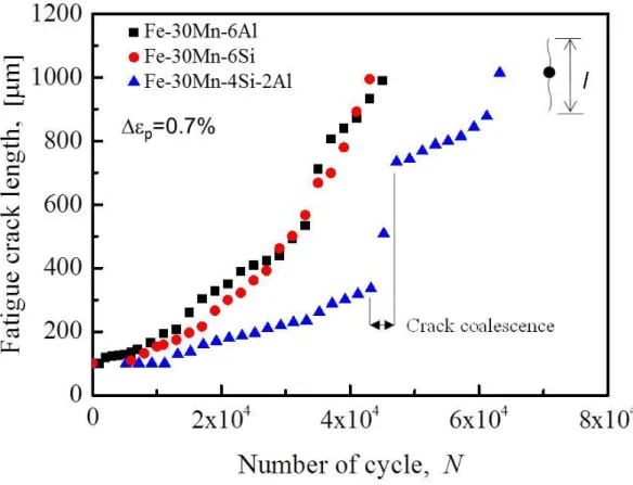
The bending fatigue tests were performed under fully reversed loading conditions at room temperature. The fatigue tests were conducted under an optical microscope with a total strain range of 0.7% and at a frequency of 6 Hz. The fatigue-crack length (l; see Fig. 1(d) for the definition of l) was directly measured from images obtained with the optical microscope. The fatigue tests were conducted until l reached 1 mm.
After the bending fatigue tests, the specimens were mechanically polished to remove the deformation-induced topography. The microstructure at the crack tips was then
17
observed via electron-backscatter diffraction (EBSD) measurements. All of the EBSD measurements were conducted with a beam step-size of 50 nm and an accelerating voltage of 20 kV. In addition, to observe the striations that arise from mode Ⅰ fatigue-crack growth, additional specimens with drilled holes were fractured by fatigue under the same conditions as the in situ experiments. The fracture surfaces of these specimens were then observed via scanning electron microscopy (SEM) at an accelerating voltage of 15 kV.
18
2.3 Results
2.3.1 Fatigue crack growth rate
Fig. 2.2 shows l as a function of the number of cycles (N) for each alloy. The fatigue crack growth rates of the Fe-30Mn-6Al and Fe-30Mn-6Si alloys are comparable. Contrastingly, the fatigue crack growth rate of the Fe-30Mn-4Si-2Al alloy is markedly lower than that of the other alloys, which is similar to the trends reported in the literature [8, 9]. The sudden increase in the fatigue crack growth rate is due to the coalescence of the main crack with subcracks, as shown later. In Section 2.3.2, some characteristics of the fatigue crack growth behaviors of the three alloys are discussed by comparing the in situ images.
2.3.2 Fatigue crack growth behavior
2.3.2.1 Fe-30Mn-6Al alloy
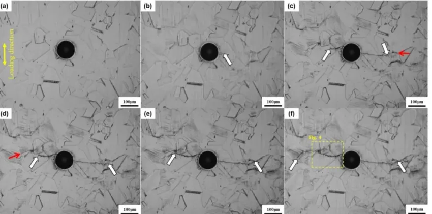
Fig. 2.3 shows in situ images of the Fe-30Mn-6Al alloy during the fatigue test. A crack was initiated at the drilled hole after 2 × 10³ cycles, and it subsequently propagated, as shown in Fig. 2.3(b). Fig. 2.3(c) shows that intensive surface reliefs are present at both the left- and right-hand side crack tips. Fig. 2.3(c-e) show that the propagation path of the left-hand side fatigue crack is a zigzag. In addition, subcracks were initiated at the grain boundaries, as indicated by the red arrows in Fig.
19
2.3(c) and (d). These subcracks eventually coalesce with the main fatigue crack (Fig.
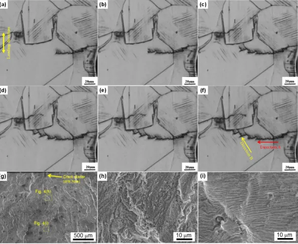
2.3(f)), which accelerates the fatigue crack propagation rate (Fig. 2.2). To analyze the growth behavior of the zigzag crack (left-hand side crack), magnified images of the outlined region in Fig. 2.3(f) were obtained (Fig. 2.4). The propagation path can be decomposed into two directions; directions A and B, as indicated by the arrow in Fig.
2.4(f). Direction A is approximately perpendicular to the loading direction, but it does not contain any specific crystallographic features. The fatigue crack propagation in direction A is accompanied by the formation of slip traces along two slip planes. On the other hand, direction B is always along pre-existing slip traces, which indicates that direction B is along the {111}γ slip plane. The fatigue crack propagation stops at the grain boundary (Fig. 2.4(d)), but it then restarts, as shown in Fig. 2.4(e). The pre-existing slip traces are present even at 1.9 × 10⁴ cycles (Fig.
2.4(a)), and the number of traces increases with the number of cycles until the main crack approaches the grain boundary, as shown in Fig. 2.4(b-d). By fatigue testing another Fe-30Mn-6Al specimen until it fractured, SEM images of the fracture surface were obtained, as shown in Fig. 2.4(g-i). Fig. 2.4(h) and (i) show that the early and late propagation regions mostly contain surface features with and without striations, respectively.
20
2.3.2.2 Fe-30Mn-4Si-2Al alloy
Fig. 2.5 shows in situ images of the Fe-30Mn-4Si-2Al alloy during the fatigue test.
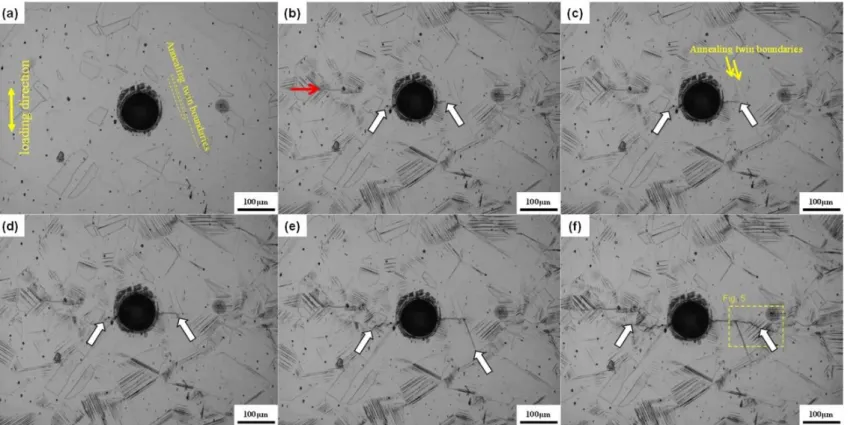
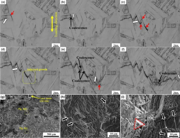
Fig. 2.5(b) shows that a considerable amount of deformation-induced plate-like products has formed. It has been reported that these plate-like products are mainly ε- martensite [8]. A subcrack was initiated at a grain boundary at 5.0 × 10³ cycles, with the main crack initiated at 1.5 × 10⁴ cycles, as shown in Fig. 2.5(b). The crack on the right-hand side reaches annealing twin boundaries, and then continues to propagate along the twin boundaries, as shown in Fig. 2.5(c) and (d). The fatigue crack branched to the perpendicular direction to the loading direction and then it is deflected again along the second annealing twin boundary (Fig. 2.5(e)); this deflection delayed the fatigue crack growth. After the crack passes through the annealing twin boundaries, the crack propagation occurs along a zigzag path (Fig.
2.5(f)). The zigzag propagation can be clearly seen in Fig. 2.6. Fig. 2.6(a) shows that a considerable amount of the plate-like products is present in front of the main crack tip. These plate-like products are ε-martensite, as shown by the phase map (Fig.
2.6(g)). By fatigue testing another Fe-30Mn-4Si-2Al specimen until it fractured, SEM image of the fracture surface were obtained, as shown in Fig. 2.6(i-k). Fig.
2.6(j) shows that the early propagation region exhibits a fracture surface without striation. Even though the fracture surface partially exhibits striation-like features (Fig. 2.6(k)), the distance between the striations (approximately 1-2 μm) corresponds to the spacing or thickness of the ε-martensite plates rather than the fatigue crack propagation rate. Even the late propagation region does not exhibit clear striation,
21
and it contains features that are similar to those reported for tensile fractures that are associated with ε-martensitic transformation [10, 11].
2.3.2.3 Fe-30Mn-6Si alloy
Fig. 2.7 shows in situ images of the Fe-30Mn-6Si alloy during the fatigue test. Fig.
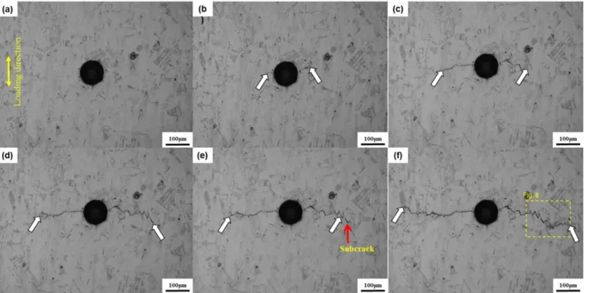
2.7(a) shows that before the fatigue test was performed, thermally induced ε- martensite was present. Crack initiation occurred at 6.0 × 10³ cycles at the right-hand side of the drill hole, while a crack was initiated at the left-hand side of the drill hole at 1.3 × 10⁴ cycles (Fig. 2.7(b)). However, the fatigue crack growth on the left-hand side is faster than that of the right-hand side (Fig. 2.7(c)). In addition, there is a considerable amount of thermally induced ε-martensite near the right-hand side crack tip, while the region around the left-hand side of the drill hole only exhibits a small amount. Fig. 2.7(d) shows that the crack growth on the right-hand side creates a zigzag propagation path. Moreover, a subcrack then forms and coalesces with the main crack (Fig. 2.7(e) and (f)). To understand this crack growth behavior, magnified images of the zigzag region were obtained (Fig. 2.8). Fig. 2.8(a) shows the formation of a subcrack near the main crack tip. The main crack then coalesces with the subcrack, which accelerates the fatigue crack growth (Fig. 2.8(b)); this is similar to the coalescence observed in Fig. 2.7(f). Furthermore, Fig. 2.8(c-f) show that the coalescence of the main crack with subcracks occurs repeatedly. As has been described in Sections 2.3.2.1 and 2.3.2.2, the fracture surface of a different specimen composed of the same alloy was observed via SEM (Fig. 2.8(g-i)). In contrast to the
22
other alloys, Fig. 2.8(h) shows that a considerable number of secondary cracks are present on the fracture surface, as indicated by the arrows. Fig. 2.8(i) shows that these secondary cracks and steps become clearer as l increases. Moreover, the red broken like in Fig. 2.8(i) indicates the presence of a pyramidal surface feature.
2.3.3 Microstructural features at the crack tips
Fig. 2.9 shows the results of the EBSD measurements performed around the fatigue crack tip in the Fe-30Mn-6Al alloy after the fatigue test was completed. The phase map shown in Fig. 2.9(b) indicates that no ε-martensite has formed near the crack tip. In addition, the image quality (IQ) map (Fig. 2.9(c)) does not indicate the presence of plates, which indicate that neither thin mechanical twin plates nor ε- martensite formed during this fatigue test. Furthermore, the {111}γ plane traces have been highlighted in the IQ map, which indicate that the majority of the fatigue crack growths along the {111}γ planes.
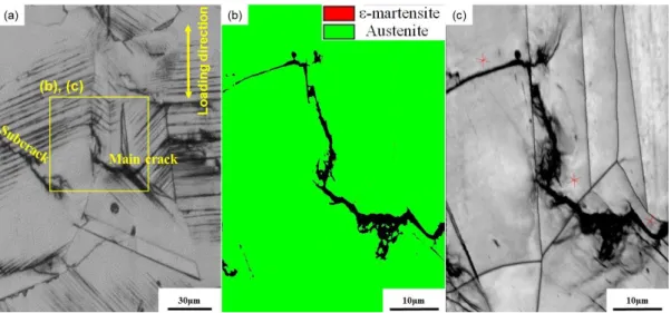
Fig. 2.10 shows the results of the EBSD measurements performed around the fatigue crack tip in the Fe-30Mn-4Si-2Al alloy after the fatigue test was completed.
Fig. 2.10(b) shows that deformation-induced ε-martensitic transformation have occurred near the fatigue crack tip. In addition, the fatigue crack has propagated along γ/ε-interfaces when the propagation path is aligned with the {111}γ planes.
Fig. 2.11 shows the results of the EBSD measurements performed around the fatigue crack tip in the Fe-30Mn-6Si alloy after the fatigue test was completed. Fig.
2.11(b) shows that a considerable amount of ε-martensite plates can be clearly seen
23
in the IQ image (Fig. 2.11(c)). The majority of the fatigue crack along the {111}γ
planes, which most likely corresponds to the γ/ε-interfaces, as discussed in Section 2.4.1.
2.3.4 Crack opening and closing processes during one cycle
Fig. 2.12(a-i) show the crack opening and closing processes in the Fe-30Mn-4Si- 2Al alloy during one cycle. Here, the both main and subcracks are present in the images. The plates observed around the cracks are ε-martensite, as shown by the phase and IQ maps (Fig. 2.12(j) and (k), respectively). A considerable number of subcracks are present along the γ/ε-interfaces, as shown in Fig. 2.5 and 2.12. In addition, these subcracks are often aligned parallel to the main crack. Furthermore, the subcracks usually grow until a critical length is achieved, which corresponding to approximately the grain size. Fig. 2.12(a-i) shows that the main crack and subcracks open and close simultaneously.
24
2.4 Discussion
2.4.1 Crack propagation path along the {111}γ planes; similar behaviors produced by different underlying mechanisms
The fatigue cracks of the three alloys investigated in this study mainly propagated along the {111}γ planes. That is, the fatigue crack propagation paths look similar regardless of the composition. However, when studied in detail, the underlying propagation mechanisms in the three alloys are extremely different. The Fe-30Mn- 6Al alloy exhibited neither mechanical twins nor ε-martensite, as shown in Fig. 2.9.
Therefore, the fatigue crack propagation along the {111}γ planes is believed to stem from slip localization. Dislocation planar slip and the resulting persistent Lüders banding (PLB) are the most likely candidates for the fatigue propagation mechanisms in the Fe-30Mn-6Al alloy [12, 13]. Even though the SFE of the Fe- 30Mn-6Al alloy is relatively high compared to that of the other alloys, the SFE divided by the shear modulus is approximately 0.9 mJ/(m2 ·GPa) (Shear modulus = 65 GPa [24]. SFE = 60 mJ/m2 [9]). This value is lower than that of other face- centered cubic (FCC) alloys, such as pure Cu (approximately 1.6 mJ/(m2 ·GPa) [15]), which exhibits frequent cross slips that result in persistent slip banding [16].
Accordingly, a low SFE is believed to promote intensive planar dislocation slip, which causes plastic strain localization (i.e., PLB) [12, 13]. In addition, PLB has been reported to initiate fatigue cracks [13, 16]. Therefore, because PLB forms along the slip plane, the fatigue crack in an FCC alloy with a relatively low SFE propagates along the {111}γ planes. The zigzag fatigue crack growth shown in Fig. 2.4 is the
25
result of a combination of fatigue phenomena: PLB and conventional mode Ⅰ propagation that is accompanied by the formation of slip traces on different slip planes, as shown in Fig. 2.4. In addition, the conventional mode Ⅰ propagation can be explained with a blunting and re-sharpening mechanism. The blunting/re-sharpening and PLB mechanisms correspond to the crack propagation along the A and B directions, respectively. Furthermore, the blunting/re-sharpening and PLB processes are accompanied by striation and brittle-like features, respectively. According to the fractographic analysis (Fig. 2.4(g-i)), the early and late fatigue crack propagation behaviors are dominated by the PLB and blunting/re-sharpening behaviors are dominated by the PLB and blunting/re-sharpening mechanisms, respectively. The zigzag propagation that stems from the combination of these mechanisms is believed to be an intermediate fatigue crack propagation behavior. One possible reason for the change in the propagation mechanism is the difference between the number of dislocations emitted from the crack tips of short and long fatigue cracks. When numerous emitted dislocations pile up around the crack tip during a single cycle, cross slip occurs to accommodate the back stress. Accordingly, the strain distribution is relatively homogenous, which assists the occurrence of the typical mode Ⅰ fatigue crack propagation.
In contrast, when the fatigue crack growth path lies along the {111}γ planes in the Fe-30Mn-4Si-2Al and Fe-30Mn-6Si alloys, the mechanism that causes the crack propagation is the formation of ε-martensite. When a crack propagates along the {111}γ planes, the γ/ε-interface can be considered the crack propagation path because the γ/ε-interface always satisfies the Shoji-Nishiyama relationship [17]. The γ/ε-
26
interface can be the preferred fatigue crack propagation path because of the two following factors. The first factor is the low resistance against brittle-like cracking on the γ/ε-interface [11, 18]. This is because a {111}γ plane is parallel to the basal plane of ε-martensite, and therefore, the dislocation motions of the other {111}γ
planes are strongly inhibited at the γ/ε-interface. Thus, the stress concentration at the γ/ε-interface causes brittle-like cracking. The second factor is the reversible motion of leading partial dislocations on the γ/ε-interface [19, 20]. It has been reported that ε-martensite grows through leading dislocation motions on every other {111}γ plane.
Therefore, because the ε-martensite in Fe-30Mn-Si-based alloys exhibits shape- memory effect-like deformation-induced reverse transformation [19, 20], the reverse transformation mostly occurs via the reverse motion of leading partial dislocations.
Thus, as long as reversible ε-martensitic transformation can occur effectively, the dislocation motions are activated mainly on the γ/ε-interface. During the reversible dislocation motions, irreversible lattice defects, such as residual dislocations that are due to the forward/reverse transformations, might from, which causes the fatigue crack propagation at the γ/ε-interface. Moreover, as shown in Fig. 2.11, there is a considerable number of intersecting ε-martensite domains in the Fe-30Mn-6Si alloy.
As has been reported for Fe-Mn-Si-based shape memory alloys, this intersection requires the formation of complex microstructures, such as FCC phases and hexagonal close-packed (HCP) twins [21-23], which may reduce the reversibility of the deformation-induced transformation. Therefore, the irreversibility of these intersections could also be a reason for the preferential formation of fatigue damage at ε-martensite plates during low cycle fatigue. The resulting {111}γ fatigue crack propagation is a cause of the formation of striation-free features on the fracture
27
surface (Fig. 2.6(j) and 2.8(h)). If a considerable amount of ε-martensite plates is activated on multiple slip planes, the smoothness of the fatigue crack propagation is disturbed at the γ/ε-interfaces, which results in the striation-like features (Fig. 2.6(k)) with a spacing that corresponds to the spacing or thickness of the ε-martensite plates.
In addition, fatigue crack propagation along annealing twin boundaries in a {111}γ
plane was also observed (Fig. 2.6). The fatigue crack growth behavior shown in Fig.
2.6 indicates both the positive and negative effects of annealing twin boundaries on the resistance against fatigue crack growth. First, the fatigue crack impinged on the annealing twin boundary. Then, the fatigue crack propagated along the same twin boundary. The former indicates that twin boundaries that are aligned perpendicular to the crack propagation direction can inhibit crack growth, while the latter implies that the twin boundary is a preferred site for the accumulation of fatigue damage. Σ3 coherent twin boundaries have been reported to act as string obstacles against dislocation motions. This is because a large amount of energy is required for dislocation dissociation to occur at twin boundaries [24, 25]. The dislocation dissociation is indispensably needed for the dislocation to penetrate the coherent boundary [26, 27], inhibiting the further dislocation motions at the twin boundary.
This property of twin boundaries contributes to the prevention of fatigue crack growth. In contrast, the ease with which fatigue cracks are initiated at twin boundaries has also been reported by previous studies [24, 28-30]. Specifically, it has been reported that intersections between slip bands and twin boundaries act as the initiation sites for cracks [28]. The fatigue damage-induced initiation of cracks is believed to occur through the accumulation of irreversible lattice defects on the twin
28
boundary. As mentioned in Section 2.4.1, dislocation penetration across a coherent twin boundary requires dislocation dissociation. The dislocation dissociation results in an irreversible dislocation. For example, a dislocation dissociation at a twin boundary can be expressed by the reaction shown in Eq. (1) [26]:
1
2[1̅01](111)111
6[1̅14](511̅̅̅̅̅) + 1
6[211̅̅̅̅̅](1̅11) (1)
where [1̅01](111) represents the incident dislocation and the (1̅11) plane is the obstacle twin boundary. The slip plane and direction can be expressed by indices in the matrix. That is, (1/6) [1̅14](511̅̅̅̅̅) corresponds to a perfect dislocation at the twin boundary. Fig. 2.13 shows a schematic diagram for the various interactions between the dislocation and coherent twin boundary. A (1/6) [211̅̅̅̅̅](1̅11) dislocation is generated when the incident dislocation passes through the (1̅11) twin boundary.
Even when a (1/6) [1̅14](511̅̅̅̅̅) dislocation completes the reverse motion during the compression process of the fatigue, the dislocation dissociation for the dislocation penetration across the twin boundary in the reverse motion requires another dislocation that corresponds to a (1/6) [211̅̅̅̅̅](1̅11) dislocation during the tension process. Therefore, irreversible dislocations are accumulated through the repetition of dislocation dissociations at the twin boundary, which results in the fatigue damage-induced formation of crack at the twin boundary.
29
2.4.2 Effects of subcracks: coalescence and crack toughening
In addition to the growth of the main crack, subcracks formed during the fatigue tests, especially in the Fe-30Mn-4Si-2Al and Fe-30Mn-6Si alloys. The formation of subcracks has two effects on fatigue crack growth: coalescence with the main crack and crack toughening. The former and latter accelerates and decelerates fatigue crack growth, respectively. The formation of subcracks near the tip of the main crack was common in the Fe-30Mn-6Si alloy. Therefore, because the propagation proceeds via the repeated coalescence of the main crack was common in the Fe-30Mn-6Si alloy.
Therefore, because the propagation proceeds via the repeated coalescence of the main crack with the subcracks, the fatigue crack propagation of the Fe-30Mn-6Si alloy was discontinuous. As a result of this coalescence, secondary cracks and steps appeared in the fracture surface of this alloy, as shown in Fig. 2.8(h) and (i).
Furthermore, the pyramidal surface feature in Fig. 2.8(i) can also be explained by either coalescence or propagation along three different {111}γ planes.
On the other hand, the coplanar subcracks of the Fe-30Mn-4Si-2Al alloy did not appear near the tip of the main crack. Instead, the subcracks formed beside the main crack, as shown in Fig. 2.12. The subcracks beside the main crack can decelerate the fatigue crack growth through two processes. The first process is stress redistribution, which occurs because of the release of residual stress at a crack tip during subcrack initiation and propagation [4]. This behavior enhances the resistance against the fatigue crack propagation of the main crack through a crack tip shielding mechanism [5]. The second process is a reduction in the crack tip opening displacement (CTOD),
30
which arises from the opening of subcracks, such as the one shown in Fig. 2.12.
Therefore, because the fatigue tests performed in this study were strain-controlled, the CTOD of the main crack at the maximum strain decreases when non-coplanar subcracks of significant length are present. As we proposed in our previous study [1], these microscopic changes in fatigue can be classified into two cases: crack propagation-induced events and macroscopic deformation-induced events. The latter does not depend on when the main crack initiation and propagation occurs. Thus, the most important factor controlling the fatigue crack growth of the Fe-30Mn-4Si-2Al alloy is the crack propagation-induced event. The effects of stress redistribution can be categorized as crack propagation-induced event. On the other hand, a reduction in the CTOD can be categorized as a macroscopic deformation-induced event, which indicates that the reduction of the CTOD is a minor factor in the deceleration of crack growth under the conditions of this study. However, the contribution from the reduction of the CTOD can be enhanced by greatly increasing the number of subcracks. Therefore, reducing the CTOD may significantly contribute to the deceleration of crack growth when under extreme conditions that cause the formation of many subcracks.
2.4.3 Factors affecting fatigue crack growth: why does the Fe-30Mn-4Si-2Al alloy show the outstanding fatigue resistance?
From the viewpoint of microstructural evolution, the deformation-induced ε- martensitic transformation plays an important role in fatigue crack growth. The effects of the chemical composition on the phase stability are the most crucial factors
31
because it will affect the behaviors of both the forward and reverse transformation.
The stability of the austenite phase to ε-phase of in the Fe-30Mn-4Si-2Al alloy is lower than that of the Fe-30Mn-6Al alloy, which allows the ε-martensitic transformation to occur, but it is higher than that of the Fe-30Mn-6Si alloy, which facilities the deformation-induced reverse transformation at room temperature. In addition to the thermodynamic effect, the two effects of ε-martensitic transformation on fatigue crack growth must be considered: the promotion of fatigue crack formation on γ/ε-interface and the suppression of slip-related strain localization at the crack tip. The promotion of fatigue crack formation has both positive and negative effects on fatigue crack growth. The negative effect is the coalescence with the main crack, which accelerates fatigue crack growth. The positive effect is the crack toughening, which is associated with crack tip shielding and a reduction in the CTOD at the maximum strain during a cycle. Moreover, the evolution of γ/ε- interface fatigue damage produces a zigzag fatigue crack propagation path along the {111}γ plane, which assists the roughness-induced crack closure [2, 3]. The suppression of slip related strain localization is attributed to the reversible motion of leading partial dislocations, which inhibits PLB that stems from the accumulation of irreversible lattice defects. Therefore, because PLB causes fatigue damage evolution, its suppression decelerates fatigue crack growth.
In this context, the behavior of ε-martensitic transformation must be controlled to achieve an exceptional resistance against low cycle fatigue crack growth, such as that exhibited by the Fe-30Mn-4Si-2Al alloy (Fig. 2.2). For example, the Fe-30Mn- 6Al alloy contains no ε-martensite, and hence, it does not receive the positive effects
32
of ε-martensite, which results in the lower resistance against fatigue compared to the Fe-30Mn-4Si-2Al alloy. In contrast, in the case of the Fe-30Mn-6Si alloy, a considerable number of subcracks preferentially formed near the crack tip, which promoted fatigue crack growth by coalescing with the main crack. The ease with which the subcracks formed is probably because of the higher amount of ε- martensite. The high amount of ε-martensite increases the degree of stress concentration and decreases the reversibility because of intersections of ε-martensite plates. Furthermore, the addition of Si is known to have a significant effect to deteriorate the plasticity of steels [31]. The reduction in plasticity potentially causes the γ/ε-interface to crack more easily. The brittle features of ε-martensite-related cracks can be clearly observed in tensile tests when more than 6% of Si is added to Fe-high-Mn alloys [11].
33
2.5 Conclusions
In this study, the microstructural evolution of Fe-30Mn-6Al, Fe-30Mn-4Si-2Al, and Fe-30Mn-6Si alloys during strain-controlled bending fatigue tests was observed in situ. From the results, the factors that produce the superior resistance of the Fe- 30Mn-4Si-2Al alloy against low cycle fatigue were determined in terms of the crack propagation behavior. The main conclusions are summarized below.
(1) The Fe-30Mn-6Al alloy exhibited fatigue crack growth along the {111}γ plane in addition to conventional mode Ⅰ propagation. The fatigue crack propagation along the {111}γ plane is caused by the strain localization and the subsequent fatigue crack formation.
(2) The Fe-30Mn-4Si-2Al and Fe-30Mn-6Si alloys also exhibited fatigue-crack growth along the {111}γ plane. However, the propagation mechanisms involved are not the same as that of the Fe-30Mn-6Al alloy. That is, the fatigue cracks in the Fe-30Mn-4Si-2Al and Fe-30Mn-6Si alloys propagated along the γ/ε-interfaces. The fatigue crack propagation along the γ/ε-interfaces causes the formation of a zigzag propagation path. The zigzag propagation path is believed to decelerate fatigue crack growth because of the enhanced roughness-induced crack closure.
(3) Subcracks that formed near the crack tip coalesced with the main crack, which accelerated crack growth in the Fe-30Mn-6Si alloy. In contrast, the subcracks in the Fe-30Mn-4Si-2Al alloy did not coalesce with the main crack. This is
34
believed to decelerate fatigue crack growth because of the stress redistribution and a reduction in the CTOD, which stem from the opening of subcracks.
Hence, in terms of crack growth, the ε-martensitic transformation has three positive effects: 1) the suppression of strain localization; 2) zigzag crack propagation, which enhances roughness-induced crack closure; and 3) subcrack formation, which induces crack-toughening, such as the stress redistribution. However, the ε- martensitic transformation also has a negative effect on crack growth, i.e., it causes subcrack initiation, which leads to the subcrack coalescence with the main crack.
The ε-martensitic transformation in the Fe-30Mn-4Si-2Al alloy is optimized so that the three positive effects are maximized while the negative effect is minimized, which results in the superior resistance of the alloy against low cycle fatigue. In future works, the optimal plasticity, amount (phase stability), and morphology of ε- martensite must be determined, and its associated subcrack formation behavior that assists crack toughening and roughness-induced crack closure without coalescence with the main crack should be investigated further.
35
References
.
[1] H. Li, M. Koyama, T. Sawaguchi, K. Tsuzaki, H. Noguchi, Importance of crack propagation-induced ε-martensite in strain-controlled low-cycle fatigue of high-Mn austenitic steel, Phill. Mag. Lett. 95 (2015) 303-311.
[2] G. Gray, J. Williams, A. Thompson, Roughness-induced crack closure: an explanation for microstructurally sensitive fatigue crack growth, Metall. Trans. A 14 (1983) 421-433.
[3] R. Ritchie, S. Suresh, Some considerations on fatigue crack closure at near threshold stress intensities due to fracture surface morphology, Metall. Trans. A 13 (1982) 937-940.
[4] D.K.M. Shum, J.W. Hutchinson, On toughening by microcracks, Mech.
Mater. 9 (1990) 83-91.
[5] R.O. Ritchie, workshop on the mechanics and physics of crack growth:
application to life prediction mechanisms of fatigue crack propagation in metals, ceramics and composites: role of crack tip shielding, Mater. Sci. Eng. A 103 (1988) 15-28.
[6] K. Le Biavant, S. Pommier, C. Prioul, Local texture and fatigue crack initiation in a Ti-6Al-4V titanium alloy, Fatigue Fract. Eng. Mater. Struct. 25 (2002) 527-545.
[7] T. Sawaguchi, I. Nikulin, K. Ogawa, K. Sekido
[8] Z.-J. Xi, M. Koyama, Y. Yoshida, N. Yoshimura, K. Ushioda, H. Noguchi, Effects of cementite morphology on short-fatigue-crack propagation in binary Fe-
36
C steel, Phill. Mag. Lett. (2015) 1-8.
[9] I. Nikulin, T. Sawaguchi, K. Tsuzaki, Effect of alloying composition on low-cycle fatigue properties and microstructure of Fe-30Mn-(6-x)Si-xAl TRIP/TWIP alloys, Mater. Sci. Eng. A 587 (2013) 192-200.
[10] T. Sawaguchi, I. Nikulin, K. Ogawa, K. Sekido, S. Takamori, T. Maruyama, Y. Chiba, A. Kushibe, Y. Inoue, K. Tsuzaki, Designing Fe-Mn-Si alloys with improved low-cycle fatigue lives, Scr. Mater. 99 (2015) 49-52.
[11] Y.S. Chun, J.S. Kim, K.-T. Park, Y.-K. Lee, C.S. Lee, Role of 3 martensite in tensile properties and hydrogen degradation of high-Mn steels, Mater. Sci. Eng.
A 533 (2012) 87-95.
[12] M. Koyama, T. Sawaguchi, K. Tsuzaki, Effects of Si on tensile properties associated with deformation-induced ε-martensitic transformation in high Mn austenitic alloys, Mater. Trans. 56 (2015) 819-825.
[13] L. Buchinger, A.S. Cheng, S. Stanzl, C. Laird, The cyclic stress-strain response and dislocation structures of Cu-16 at.% Al alloy III: single crystals fatigued at low strain amplitudes, Mater. Sci. Eng. 80 (1986) 155-167.
[14] S.I. Hong, C. Laird, Fatigue crack initiation and growth behavior of Cu-16 at.% a1 single crystals, Fatigue Fract. Eng. Mater. Struct. 14 (1991) 143-169.
[15] S. Allain, J.P. Chateau, O. Bouaziz, A physical model of the twinning- induced plasticity effect in a high manganese austenitic steel, Mater. Sci. Eng. A 387-389 (2004) 143-147.
[16] Y.H. Zhao, Z. Horita, T.G. Langdon, Y.T. Zhu, Evolution of defect structures during cold rolling of ultrafine-grained Cu and Cu-Zn alloys: influence of stacking fault energy, Mater. Sci. Eng. A 474 (2008) 342-347.
37
[17] P. Lukáš, L. Kunz, Cyclic slip localisation and fatigue crack initiation in fcc single crystals, Mater. Sci. Eng. A 314 (2001) 75-80.
[18] Z. Nishiyama, Martensitic Transformation, Elsevier, 2012.
[19] S. Takaki, T. Furuya, Y. Tokunaga, Effect of Si and Al additions on the low temperature toughness and fracture mode of Fe-27Mn alloys, ISIJ Int. 30 (1990) 632-638.
[20] T. Sawaguchi, P. Sahu, T. Kikuchi, K. Ogawa, S. Kajiwara, A. Kushibe, M.
Higashino, T. Ogawa, Vibration mitigation by the reversible fcc/hcp martensitic transformation during cyclic tension-compression loading of an Fe-Mn-Si-based shape memory alloy, Scr. Mater. 54 (2006) 1885-1890.
[21] T. Sawaguchi, L.G. Bujoreanu, T. Kikuchi, K. Ogawa, M. Koyama, M.
Murakami, Mechanism of reversible transformation-induced plasticity of Fe-Mn- Si shape memory alloys, Scr. Mater. 59 (2008) 826-829.
[22] J.H. Yang, C.M. Wayman, Development of Fe-based shape memory alloys associated with face-centered cubic-hexagonal close-packed martensitic transformations: part III. microstructures, Metall. Trans. A 23 (1992) 1445-1454.
[23] S. Matsumoto, A. Sato, T. Mori, Formation of h.c.p. and f.c.c. twins in an Fe·Mn·Cr·Si·Ni alloy, Acta Metall. 42 (1994) 1207-1213.
[24] X. Zhang, T. Sawaguchi, K. Ogawa, F. Yin, X. Zhao, A structure created by intersecting ε martensite variant plates in a high-manganese steel, Phil. Mag. Lett.
91 (2011) 4410-4426.
[25] L. Rémy, The interaction between slip and twinning systems and the influence of twinning on the mechanical behavior of fcc metals and alloys, Metall.
Trans. A 12 (1981) 387-408.
38
[26] M.D. Sangid, T. Ezaz, H. Sehitoglu, I.M. Robertson, Energy of slip transmission and nucleation at grain boundaries, Acta Mater. 59 (2011) 283-296.
[27] S. Mahajan, G.Y. Chin, Twin-slip, twin-twin and slip-twin interactions in Co-8 wt.% Fe alloy single crystals, Acta Metall. 21 (1973) 173-179.
[28] L. Rémy, Twin-slip interaction in f.c.c. crystals, Acta Metall. 25 (1977) 711- 714.
[29] A.S. Hamada, L.P. Karjalainen, J. Puustinen, Fatigue behavior of high-Mn TWIP steels, Mater. Sci. Eng. A 517 (2009) 68-77.
[30] S. Qu, P. Zhang, S.D. Wu, Q.S. Zang, Z.F. Zhang, Twin boundaries: strong or weak? Scr. Mater. 59 (2008) 1131-1134.
[31] Z.J. Zhang, P. Zhang, L.L. Li, Z.F. Zhang, Fatigue cracking at twin boundaries: effects of crystallographic orientation and stacking fault energy, Acta Mater. 60 (2012) 3113-3127.
[32] W.W. Gerberich, Y.T. Chen, D.G. Atteridge, T. Johnson, Plastic flow of Fe binary alloys-II. Application of the description to the ductile-brittle transition, Acta Metall. 29 (1981) 1187-1201.
39
Fig. 2.1 (a) Top view of the sample geometry used for the fatigue tests. (b) Detailed schematic of the shape of the drilled hole that is indicated in (a) (d = diameter, h = height). (c) Magnified side view showing the position of the drill hole and the loading direction. (d) Definition of the crack length (l) that was used in this study.
Fig. 2.2 Fatigue crack length (l) as a function of the number of cycles (N) for a maximum l of 1 mm for the three alloys tested.
40
Fig. 2.3 In situ images of the Fe-30Mn-6Al alloy at various points during the fatigue test: (a) undeformed, (b) 6.0 × 10³, (c) 1.9 × 10⁴, (d) 2.3
× 104, (e) 2.9 × 10⁴, and (f) 3.3 × 10⁴ cycles. The white arrows indicate the main crack tips. The red arrows indicate subcracks.
41
Fig. 2.4 (a-f) In situ images of the Fe-30Mn-6Al alloy at various points during the fatigue test: (a) 1.9 × 10⁴, (b) 2.1 × 10⁴, (c) 2.3 × 10⁴, (d) 2.5 × 10⁴, (e) 2.7 × 10⁴, and (f) 2.9 × 10⁴ cycles. (g-i) SEM images of the fatigue fracture surface of the same alloy (but a different specimen): (g) overview, and (h) early and (i) late propagation regions.
42
Fig. 2.5 In situ images of the Fe-30Mn-4Si-2Al alloy at various points during the fatigue test: (a) undeformed, (b) 1.9 × 10⁴, (c) 2.1 × 10⁴, (d) 2.5 × 10⁴, (e) 3.3 × 10⁴, and (f) 4.3 × 10⁴ cycles. The white arrows indicate the main crack tips. The broken yellow lines indicate annealing twin boundaries. The red arrow indicates a subcrack.
43
Fig. 2.6 (a-f) In-situ images of the Fe-30Mn-4Si-2Al alloy at various points during the fatigue test: (a) 3.1 × 10⁴ cycles, (b) 3.5 × 10⁴ cycles, (c) 3.7 × 10⁴ cycles, (d) 3.9
× 104 cycles, (e) 4.1 × 10⁴ cycles, and (f) 4.3 × 10⁴ cycles. (g) Phase and (h) image quality maps corresponding to the outlined region in (f). (i-l) SEM images of the fatigue fracture surface of the same alloy (but a different specimen): (i) overview, and (j) early, (k) intermediate, and (l) late propagation regions.
44
Fig. 2.7 In situ images of the Fe-30Mn-6Si alloy at various points during the fatigue test: (a) undeformed, (b) 1.3 × 10⁴, (c) 2.5 × 10⁴, (d) 2.9 × 10⁴, (e) 3.1 × 10⁴, and (f) 3.7 × 10⁴ cycles. The white arrows indicated the main crack tips. The red arrows indicate subcracks.
45
Fig. 2.8 (a-f) In situ images of the Fe-30Mn-6Si alloy at various points during the fatigue test: (a) 2.5 × 10⁴ cycles, (b) 2.7 × 10⁴ cycles, (c) 2.9 × 10⁴ cycles, (d) 3.1 × 10⁴ cycles, (e) 3.3 × 10⁴ cycles, and (f) 3.5 × 10⁴ cycles. The white arrows indicate the main crack, while the red arrows indicate the subcracks. (g-i) SEM images of the fatigue fracture surface of the same alloy (but a different specimen): (g) overview, and (h) early and (i) late propagation regions.
46
Fig. 2.9 (a) Optical microscope image of the Fe-30Mn-6Al alloy after the fatigue test (4.5 × 10⁴ cycles). (b) Phase and (c) image quality maps corresponding to (a). The red lines in the image quality map indicate {111}γ planes.
Fig. 2.10 (a) Optical microscope image of the Fe-30Mn-4Si-2Al alloy after the fatigue test (6.3 × 10⁴ cycles). (b) EBSD phase map corresponding to the outlined region in (a).
47
Fig. 2.11 (a) Optical microscope image of the Fe-30Mn-6Si alloy after the fatigue test (4.3 × 10⁴ cycles). (b) Phase and (c) image quality maps corresponding to the outlined region in (a).
48
Fig. 2.12 In situ images of the Fe-30Mn-4Si-2Al alloy during one cycle of the fatigue test. These images were taken at 6.3 × 10⁴ cycles. (a-i) The strain stages are indicated in the schematic graphs shown in the insets. (j) Phase and (k) image quality maps corresponding to the outlined region in (a).
49
Fig. 2.13 Schematic diagram of the dislocation dissociation at the twin boundary.
50
CHAPTER 3. Effects of ε-martensitic transformation on crack tip deformation, plastic damage accumulation, and slip plane cracking associated with low cycle fatigue crack growth
3.1 Introduction
In chapter 2, macroscopic fatigue crack growth behavior was observed in situ by optical microscopy. The Fe-30Mn-6Al alloy showed ductile striations on fracture surface. This result indicates that a large plastic deformation is localized at the crack tip. In contrast with the Fe-30Mn-6Al alloy, the Fe-30Mn-4Si-2Al and Fe-30Mn-6Si alloys showed considerable ε-martensite near the crack path. However, the role of ε- martensite was quite different. Even the-30Mn-6Si alloy has been known to exhibit a great work hardening capacity, the occurrence of premature fracture that associated with ε-martensite-related cracking can cause extremely low elongation [1, 2]. The Fe-30Mn-4Si-2Al alloy showed the striation-like patterns on fracture surface of long crack region as shown in Fig. 2.6(l). Moreover, when the striation-like patterns were observed on fracture surface, the fatigue crack growth rate was still low, even though the rapidly increased fatigue crack length by crack coalescence with long subcrack as shown in Figs. 2.2, 2.6(i) and (l). These results indicate that the Fe-30Mn-4Si-2Al alloy has other effect of ε-martensitic transformation, as well as the positive effects of ε-martensitic transformation introduced in chapter 2 such as zigzag crack propagation, which enhances roughness-induced crack closure. Therefore, the further research is needed to investigate the low crack growth rate of the Fe-30Mn-4Si-2Al alloy.
51
The formation of ductile striation has been known as a result of crack blunting and re-sharpening [3, 4]. Moreover, the crack blunting and re-sharpening behavior requires a large degree of plastic strain localization [5, 6]. The low-cycle fatigue resistance of high Mn alloy is supposed that reverse transformation of ε-martensite has been recognized as the most important factor enhancing the resistance to low- cycle fatigue [7, 8]. More specifically, the reverse transformation is attributed to the forward and reverse motion of leading partials, which suppresses damage accumulation-related to low-cycle fatigue [9]. However, the relationship between the low fatigue crack growth and ε-martensitic transformation has not been thoroughly investigated in viewpoint of the localization of plastic deformation. In specific, the way in which the reverse transformation of ε-martensite decelerates the fatigue crack growth is still debatable. Moreover, we must also consider how the ε-martensitic transformation affects the deformation behavior geometrically at a crack tip based on the dislocation motions.
In order to discuss the effect of two factors mentioned above, performing a fractographic analysis and the associated electron backscatter diffraction measurements are expected to uncover the fatigue crack growth mechanism and fatigue-related plastic strain evolution, respectively. Furthermore, in order to extend the discussion from fatigue crack growth to fatigue life, the crack length dependence of the fatigue crack growth behavior must be noted. Namely, in the present study, we examine the relationship between the crack tip deformation and crack growth rate on one side, and its crack length dependency with considerations to ε-martensite cracking on the other side.
![Table 1.3 SFE and associated plastic deformation mode by chemical composition of Al and Si [8, 9, 11-13]](https://thumb-ap.123doks.com/thumbv2/123deta/9917800.1919358/15.1262.250.971.310.586/table-sfe-associated-plastic-deformation-mode-chemical-composition.webp)
![Fig. 1.1 Development of steels for structural applications in the automotive industry [1]](https://thumb-ap.123doks.com/thumbv2/123deta/9917800.1919358/16.893.172.783.178.512/fig-development-steels-structural-applications-automotive-industry.webp)
![Fig. 1.3 Nominal stress- nominal strain curves of the Fe-30Mn-6Al, Fe-30Mn-4Si- Fe-30Mn-4Si-2Al and Fe-30Mn-6Si alloys [20].](https://thumb-ap.123doks.com/thumbv2/123deta/9917800.1919358/17.893.187.761.206.637/fig-nominal-stress-nominal-strain-curves-fe-alloys.webp)