Augmentation Mechanism of Mass Transfer Among Turbulence Promoters
on Wall Surface in Rectangular Duct
Hisashi MIY ASHIT A, and Kaichiro WAKABAYASHI Department o f Chemical Engineering Toyama University, Takaoka, 933, JAPAN
ABSTRA CT
An augmentation mechanism of mass transfer was investigated phenomenologically by using turbulence promoters on the wall surface in a rectangular duct. The augmentation of local mass transfer ainong the turbulence promoters was measured by varying the diameter, the pitch of the
promoters and the clearance between the promoters and the wall. In order to examine the aug
mentation mechanism, wall shear stress, mass transfer intensi ty and turbulence intensity at the wall were measured by an electrochemical method. Further, flow behaviors were measured by visualization.
It was found phenomenologically that the augmentation of mass transfer with the clearance was caused �Y turbu lence due to reattachment flow, l arge scale eddies and increase of shear stress due to flow jet under the promoters and was caused by only turbulence on the wall surface in case of no clearance.
1. INT RODUC T IO N
I t i s well known that roughening the surface by use of turbulence promoters (requl ar geomet
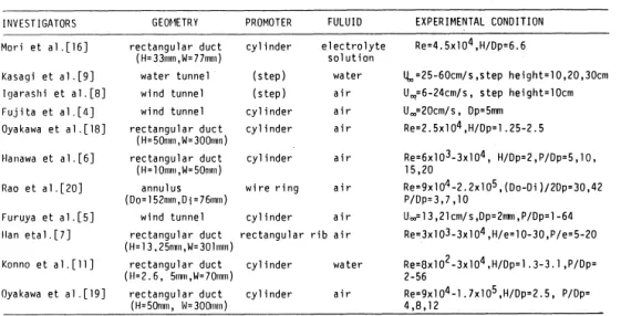
ric roughness element) on the wall surface in a duct improves the heat transfer from the surface for the design of compact heat exchanger. The increase in heat transfer i s accompanied by an increase in resistance to fluid flow. The problem of optimizing heat transfer performance for given flow friction has been studied by many investigators. S ome of them are shown in Table 1 .
I t has been found in practical applications that an increase i n flow resistance does not al
ways decrease energy efficiencies. However, few investigations of the augmentation mechanism of heat tran sfer have been published.
Mori et al( l 6) and Fujita et a!( 4) suggested that augmentation of heat transfer depends mainly on turbulence intensity near the wall surface downstream from a single cylinder turbulence promoter placed on the transfer wall in a reetangular duct .
Miyashita et al[l4) pointed out that augmentation depends on the turbulence intensity near the wall surface in the case of no clearance between promoter and wall, and depends not only on the turbulence intensity but also on the shear stress at the wall in the case of non- zero clearances in a rectangular duct.
In this paper, the augmentation ratio of local mass transfer coefficients among the promo
tres was measured by varying the diameter, the pitch of the promoter and the clearane between
H. Miyashi ta, K. Wakabayayhi : Augmentation Mechanism of Mass Transfer
promoter and wall surface. Flow behavior was observed by visualization.
mass transfer intensity at the wall and turbulence intensity close to the
Wall shear stress, wall surface were measured by an electrochemical method, in order to examine the detailed augmentation mechanism of heat/mass transfer on the wall surface among the turulence promoters in a rectangular duct.
INVESTIGATORS GE0�1ETRY PROMOTER FULUIO EXPERIMENTAL CONDITION
Mori et al.[l6] rectangular duct cylinder electrolyte Re=4. 5x 1 o4 ,H/Op=6. 6
( H= 33mm, W= 77mm) solution
Kasagi et a1.[9] water tunnel (step) water lJ., =25-60cm/ s, step height= 10,20, 30cm Igarashi et a l. [8] wind tunnel (step) air U.,=6-24cm/s, step height=lOcm Fujita et a l . [ 4] wind tunnel cylinder air U.,=20cm/s, Op=5mm
Oyakawa et al.[l8] rectangular duct
( H=50nun, W= 300mm) cylinder air Re=2.5xlo4,H/Dp=l.25-2.5 Hanawa et al. [6] rectangular duct cylinder air Re=6x 1 o3-3x l o4, H/Op=2, P /Dp=5, 10,
( H= 1 Omm, W=SO"'n) 15,20
Rao et a1.[20] annul us wire ring air Re=9xl o4 -2. 2xl o5, ( Oo-Di ) I 2Dp=30, 42
(Do=l52mm,Di=76mm) P/Dp=3,7 ,10
Furuya et a1.(5] wind tunnel cylinder air u.,= 13,21 em/ s ,Op=2mn, P /Op= 1-64 Han eta1.[7] rectangular duct rectangular rib air Rec3x 1 03-3xl o4 ,H/e= 10-30, P /e=5-20
(H=l3 ,25mm,W=30lmm)
Konno et al.[ll] rectangular duct cylinder water Re=Ox 102 -3xl o4, H/Op= l . 3-3. l , P /Dp=
(H=2.6, 5mm,W=70mm) 2-56
Oyakawa et al.[l9] rectangular duct cylinder air Re=9xl o4-l. 7xl o5 ,H/Op=2. 5, P/Dp=
(H=SOmm, 14=300nnn) 4 ,8,12
Table 1 Investigations on enhanced heat transfer using turbulence promoters
2. EXPERI MENTAL APPARATUS AND PROCEDURE
A schematic diagram of the experimental apparatus and a detail of the test section are shown in Fig. 1 and Fig. 2, respectively. The dimensions of the cross section in a duct for mass transfer measurements were 40 x 50 mm (height by width) . The test section was 2800 mm long ( 63 hydraulic diameters in length) to obtain the hydraulically fully developed flow at the mass transfer section. Following the entrance region, a mass transfer development region of 10 x90 mm preceded the cathode (10 x 360 mm) for measurement of average mass transfer coeffi
cients. Further, 1.0 mm platinium point electrodes (30 points) for the measurement of the local mass transfer coefficients, wall shear stress and mass transfer intensity were arranged at intervals of 5 mm on the nickel cathode. Two anodes (17 x 450 mm2 ) were located on the bottom side of cathode. Each electrode was isolated electrically by epoxy resin. A blunt nose
type probe with 0.3 mm platinium wire was used to measure the velocity profile in the duct.
Bulletin of Faculty of E ngineering Toyama U niversity 1985
I. Constant tefll)E'rature reservoir
2. Pul'l'l'> for fluid
3. Flow valve
4. By.pass valve
5. Manometer for fluii
flow
7
6. Channel for mass transfer
7. Crannel for flow visualization
8. Temperature controller
9. Nz-container
Fig. 1 S chematic diagram of experirrental apparatus
90
[Q,__2800-='*'-� 100 f +-- �-�:.:.__50tf -oof1+--/J�---iJ
Ni cathode
a) electrode at the wall
epoxy resin
b) point electrode
epoxy resin
Fig. 2 Details of test section and probe
3
stainless steel support
Experiments were carried out by varying the diameter of turbulence promoters Dp ( 3, 5 . 7 and 10 mm) , clearance between the promoter and the wall surface c ( 0, 1. 3, 5, 7, 10 and centre) , pitch among the promoters p (p/ Dp = 5,7 ,9,12 and 16) and flow Reynolds number Re ( 6. 64 x 103
- 1. 73 X 104) .
H. Miyashita, K. Wakabayashi : Augmentation Mechanism of Mass Transfer
In experiments for the electrochemical method, 0. 005M potassium ferri/ ferro cyanide and 2 M sodiumhydroxide used a s electrolyte solution. Temperature was set up 3ffi ±0 .5 K. The den
sity and viscosity of electrolyte were 1075 kg/ m3 and 0.0013 Pa. s (N. s/ m2 ) respectively. The di ffusion coefficient for the ferricyanide ion was 5. 776 X 10--IO m2 Is given by Mitchell ana
Hanr a tty' s correlation(2 1) , and the S chmidt number was equal to 2097.
In experiments for visualization, aluminium powder was suspended in water( 1 ). The flow pattern was observed in a transparent duct. The experimental conditions were simil ar to those for the measurement of mass transfer.
The coordinates and variables of the test section are shown in Fig. 3 .
Flow
q
pX
Turb.Jlence promoter
Fig. 3 Coordinates and notations of test section 3 . CALCUL AT I N O F T R ANS P O RT PH YS I C AL F AC T O R S
H
The mass transfer coefficients were measured by using the potassium ferri/ ferrocyanide redox electrochemical reaction as reviewed in detail by l\1izushina( 15) . The basis of the method i s that when operating at the so- called "limiting current" condition the electrochemical phenomena are limited by mass transfer at the cathode only, and hence the concentration of ferricyanide ion is zero at this electrode. Mass transfer limitations do not occur at the anode, i f its transfer area is very large relative to that at the cathode. Under these conditions, the mass transfer coefficient is given by
k =----
ne. F. A. Cb ( 1 )
To overcome ion-migration effects in a potential field, potassium ferricyanide solution is dissolved in strong electrolyte, in this case sodiumhydroxide when the concentration of this unreactive ele
ctrolyte is high compared to the concentration of ferricyanide ion, the transfer of ferricyanide ion is done ordinary diffusion or by the ordinary mass transfer mechanism with constant composition at the wall.
Bulletin of Faculty of Engineering Toyama University 1985
The princi ple of the shear stress and the fluid velocity measurement is also described by Mizushina [ 15). The wall shear stress on the bottom wall can be calcul ated from following the equation in the case of circular surface.
15 fl. i
r = 3. 55 x 10-
IJ.a.rf' ( 2 )
The above equation is given by the solution of Leveque, assuming that the velocity profile is li near and that the Prandtl number of the fluid is large.
The fluid velocity can be calculated by the following equation from l imiting current measured by a blant nose type probe.
where, a and (3 are constants given by calibration.
Mass transfer intensity is defined by the following equation.
I = 100 fk'2
ko
( 3 )
( 4 )
ko and k' is calculated from Eq. ( 1 ) , where /F2 is the root mean square value for the fluctua
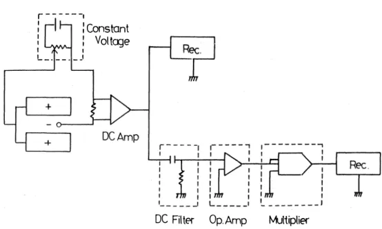
ting component of mass transfer coefficient. ko is the time averaged mass transfer coefficient in a smooth duct . Mass transfer intensity is a transport property to be obtained the information on turbulence close to the wall surface. Electric circuits for the measurements of mass trans
fer coefficient, the intensity, and fluid velocity using a probe are shown in Fig. 4 .
r---1
: I :Constant
: Voltcge
1 1
L __ ___ _ J
DC Filter Op. Amp Multiplier
Fig. 4 Electric circuits for measurement of transport factors
H. Miyashita, K . Wakabayashi : Augmentation Mechanism of Mass Transfer
4. EXPERIMENTAL RES ULTS AND DIS CUS S IN pre-experiment
Before initiating experiments with turbulence promoter, mass transfer coefficient , friction factor and velocity profile were measured for smooth duct as shown in Fig. 5, 6 and 7 , and ob
tained the following correlations, respectively.
80
,..., 60
I
20
10-2
,...,
I 8
...
-0
6
4
Sho=0.023(Ref'8(Scf-4
Re [-J
• Shtoc.
o Sha.v.
2
Fig. 5 Mass transfer coefficient for smooth duct
4
I
I I-0.25
fo =0.0791(Re)
6 8 104 Re [-]
Fig. 6 Friction factor for smooth duct 2
Bulletin of Faculty of Eng ineering Toyama University 1985
Sho = 0 . 023 (Re) 0·8(Sc) 0·4 ( 5 )
I = 0 . 0791 (Re) -0'25 ( 6 )
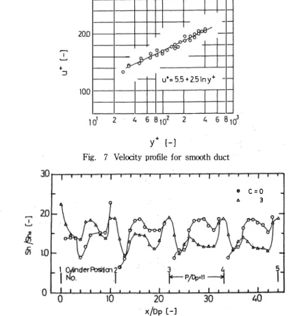
u+ = 5 . 5 + 2.5 ( lny+) (y+ > 30) ( 7 )
where, Re is based on equivalent diameter and in range of 4000 < R e < 18000 . These equations agreed with the classical well known ones within experimental errors.
The experimental equation in turbulent convective heat transfer is Nu = 0 . 023 (Re) 0·8(Pr) 0'4
( Re >8000) . ( 8 )
With the electrochemical method, mass transfer experiments where the concentration on the wall wall is zero are similar to those of heat transfer where the temperature on the wall is cons
tant . Analogy between heat and mass transfer is shown by Eq. ( 4 ) and ( 7).
Next , in order to examine the entrance effects in the interval between the turbulence pro
moters, the distributions of augmentation ratio Sh/ Sho of mass transfer among the turbulence promoters were measured for case of PI DP = 11, c = 0 and 3 as shown in Fig. 8 . From the data in the figure, it was found that the same distributions were observed downstream from the third promoter. Therefore, the experiment with the promoters was carried out in the section between the third and the fourth promoter, because of safety, though it was reported by the other articles(17, 19) which was repeated in down stream from the second promoter.
I I I I
I I
-
�
20.0
- 0 -r-- u•= 5.5 + 2.51n y•
100 I I I I
I I I J
y• [- J
Fig. 7 Velocity profile for smooth duct
0 c =0
"' 3
o �����,o����2o�J-��3�o���4�0�� i
x/Dp [-J
Fig. 8 Check for entrance effect among turbulence promoters
H . Miyashi ta, K . Wakabayashi : Augmentation Mechanism of Mass Transfer
Flo w pattern
Flow patterns among the turbulence promoters in turbulent flow for each PI DP were clearly classified according the clearance between the promoter and the wall, that is, c = 1 and � 3 as suggested by Miyashi ta ( 14) for a single promoter in a rectangular duct. Further, the flow p a t t ern was observed by visualization, in order to examine the effect on PI DP
(1) In the case o f PI Dp=5
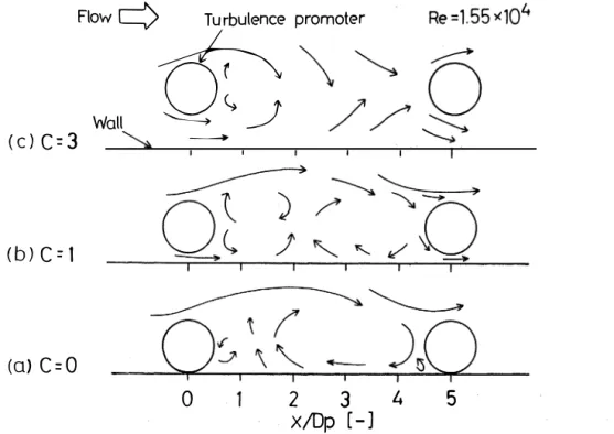
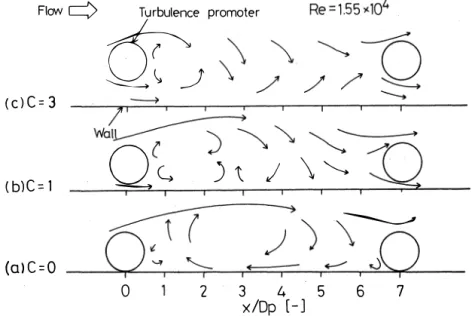
A typical sketch of the flow pattern. ith clearance for PI Dp = 5 is shown in Fig. 9 .
(C) C=3
(b)C=l
(a> C=O
c = O:
Flow c=) Turbulence Wall
�0(
� � �_)
-
0
promoter
2 3
X/Dp [ -] 4
Fig. 9 F1ow pattern for P/Dp=5 (Re=l.55 x 10') I.
5
The flow separated at the top of the promoter was not attached on the wall but collided to the next promoter. It was observed that a part of the flow formed a normal circulating flow among the promoters.
c = 1:
A couple of normal and reverse circulating flowwas observed in the section between the pro
moter and xl DP = 2 - 4 . c = 3:
A large scale eddy was formed by the combination of the top and the bottom flowof the pro
moter and Karman's vortex street was formed in back of the promoter as in the experiment( 14)
for the single promoter.
In generally, the flow in pI DP= 5 seems to stagnate among the promoters because the pitch
Bulletin of Faculty of Engineering Toyama University 1985
of promoters is small and the next promoter is located before the wake flow reaches the att ach
ment point .
(2) In the case ofpiDp=7
A typical sketch of the flowpattern with clearance for p/ DP = 7 is shown in Fig. 10.
c= O :
Flow� Turbulence promoter
&_)
(clC=3
( b)C = 1
(alC=O
71 I I I I I I I
Wa�����
Qc.
I I )\ / \"--. I IJJ
--....______,.
�-),:: .JQ
0 2 3 4 5
x/Dp [- J 6
Fig. 10 Flow pa ttern forP/Dp=7 (Re=l.55 x 104) 7
A part of the seperating flow attaches to the wall near xI Dp = 6 in front of next promoter.
The other flow collides wi th the next promoter, and normal circulating flow is formed among the promoters.
c = l :
The top flow of the promoter attaches near xI DP = 5 and the bulk flow behavior appears to make violent turbulence before the next promoter.
c = 3 :
Karman' s vortex street is formed in the same way as for p I Dp = 5, and the effect on the wall due to large scale eddies occuring from the top flow of the promoter was observed in the range of xl Dp = 3 to 4 . I t is similar to the flow pattern found in experiments for the single promoter. For c >3 , Karman's vortex street was formed for allPIDp.
(3) I n the case of p/ DP=9,11 and 16
The flow patterns corresponding to clearance c were recognized as the same as for P I DP=7 . I n conclusion, it was found that the flow pattern among the promoters distinguishedP I DP= 5 from pi DP � 7 , flom the behaviors of the separating flow having a direct influence on the augmen
tation of mass transfer on the wall .
H . Miyashita, K . Wakabayashi : Augmentation Mechanism of Mass T ransfer
DIST RIBUT I ON OF L O C AL MASS T RANS F E R C OE F F I C I ENT, W ALL SHEAR S T RES S AND M ASS T RANSFER INTENS I T Y
It may be concidered from the flow pattern that the attachment flow and large scale eddies play important roles for the augmentation of mass transfer among the promoters on the wall .
In order to discuss the mechanism of this augmentation, local mass transfer coefficients, wall shear stress and mass transfer intensity among the promoters were measured at clearances c = O , 1 and 3 , for P I DP= 5 and 9 (pI Dp;;;;. 7 ) , as typical examples of flow patterns. The coefficients were expressed as augmentation ratios, Shl S ho and I rl ro I, and then correlated withx I Dp.
( 1) General tendency
The augmentation ratio of mass transfer Shl S ho usually has a peak just under the promo
ter. This peak occurs at the same location as a peak in the absolute value of the shear stress I rl rol and the place of the minimum value of the mass transfer intensity. Therefore, it ap- pears that the augmentation of mass transfer.was caused by the thin laminar layer of the accel e
rated flow under the promoter on the wall . Wall shear streys is an i mportant factor against augmentation of mass transfer only at xI Dp= 0. Because I r I ro I is less than unity i n all sec
tions except under the promoter.
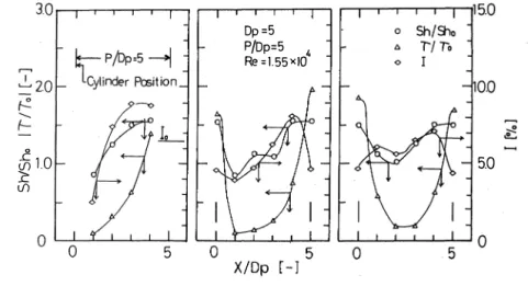
(2 ) I n the case ofpl Dp=5
The profiles of S hiS ho , I r I ro I and I among the promoters are shown in Fig. 1 1 -( a) . (b) . (c) , for c = O , 1 and 3 respectively. For c = O, the shape ofShiSho and I are only increasing to the
5\10
L: \/)
Dp=5 P/Dp=5 4
Re =1.55xiO
Fig. 1 1 Profiles of transport factors for P / Dp = 5
5.0
direction of flow and are similar. Therefore, i t may be considered that the augmentation of mass transfer i s caused by the turbulence due to the circulating eddy formed among the promo
ters near the wall . For c = 1 and 3 , both profilesSh/ S h0 have minimum values at xl DP=1 - 2 Then increasing and approaches the values of S hi Sho at x I Dp= 0 , These profiles are similar to those of the mass transfer intensity I. Therefore, it was concluded that the augmentation at the wall surface is affected significantly by the turbulence which caused by the separating
Bulletin of Faculty of Engineering Toyama University 1985
flow or Karman's vortex street formed from the first promoter colliding with the next promoter, was caused by a high value inS hiS h o at xI DP= 4.
(3) In the case ofpl Dp=9
The profiles of S hiS h o and among the promoters are shown in Fig. 13-(a), (b) , (c) with c=
0 , 1 and 3 respectively. For c = 0 , S hi S h o have a minimum point at xI DP = 2 corresponding to at the stagnation point where reversed flow arises. It is some high values in the wide region of
( a) 3.0
I jizo
t: '
�� 10
0
(c) 10
I �20
�
�lO £
<!)
0
Dp•5
Cyhnder PIDp•9
Position� Re-1.55•10'
P/Op•9 --1
�
k_1
�
10 5 10
X/Op [-]
L
0 10
x/Op [-J
0 .
0
. 0 0
15.0 (b) 3.0 15.0
ShiSh> o Sh/':h
T/T, 1 . 7'/7',
I 0 I
0.0 �20 100
t:
::<: .1\ L l
....
5.0- ;;; 10 5.0-
0 0 5 0
0 10
x/Op [-J
15.0
Sh/Sh,
T/To
I 00
50-:i Fig. 12 ( a) Profiles of transport factors for P/ Dp=9 ( c=O) ( b) Profiles of transport factors· for P/ Dp=9 ( c=1)
0 ( c) Profiles of transport factors for P/ Dp=9 ( c= 3 ) xI Dp = 3 - 8 and i s quite similar to the mass transfer intensity profile. Accorbingly, i t i s re
congnized that turbul ence due to attachment near the wall i s a factor in the augmentation of mass transfer.
For c = 1 , S hiS h o gives a slightly lower value at xI DP= 4 but has high values over the whole range except for just under the promoter. This profile is quite similar to the mass trans
fer intensity. Accordingly, it is recognized that turbulence due to the attachment flow is also a factor for the augmentation of mass transfer.
For c = 3 , S hiS h o has a peak at xI DP= 3 -4 as in the experiments for a single promoter.
The peak corresponds to that of the mass transfer intensity. This means that the augmen- tation of mass transfer is caused by turbulence from Karman's vortex street in the flow pattern.
CONCLUSIONS
An experimental investigation was performed to study the mechanism for the augmentation of heat transfer due to the cylinder type turbulence promoters on the wall in a rectangular duct.
In this paper, an electrochemical method using the redox system of ferrilferrocyanide ion was used in order to measure the mass transfer coefficient , wall shear stress, fluid velocity and mass transfer intensity. The augmentation mechanism of mass transfer among the promoters was explained through the behaviours of the wall shear stress, the mass transfer intensity and the flow pattern by visualization.
H . Miyashita, K . Wakabayashi : Augmentation Mechanism of Mass T ransfer
Results were as follows.
It was confirrred that the measurement by electrochemical method was correct from the agreement with wel l known correlations.
The flow patterns were cl assified by P I Dp= 5 and PI Dp� 7 , because of the existance of an attachment point among the promoters, and also cl assified by the clearance, in c= O, 1 and 3 . As c increases, a slipping fl ow occurs just under the promoter and Karman's vortex street is formed downstream of the promoter for c � 3 and any pI Dp.
I t was found that the attachment flowand large scale eddies play an important rol e in the augmentation of mass transfer among the promoters through the comparison of profiles of I r I ro I,
I and flowpattem.
P IDp= 5 : For c= O , the augmentation ofShiSho depends on the turbulence intensity/.
For c> O , it depends not only on the increasingl rl rol under the promoter (xiDp= O ) , but on the turbulence due to large scale eddies among the promoters.
p I Dp� 7 : For c= 0 , it depends on the turbulence due to the attachment flow among the promoters. For c > 0 , it depends not only on the I r I ro I under the promoter but also on the tur
bulence due to attachment flow, circulating eddies and Karman's vortex ( c� 3 ) among the pro
moters.
N O T AT I O N
A = surface area o f electrode ( cm2 )
c = clearance between turbulence promoter and wall ( mm)
Cb = bulk concentration of ferricyanide ion ( moll cm3 J
D = diffusivity of ferricyanide ion ( cm2 Is)
Dp = diameter of turbulence promoter ( mm)
d =diameter of point electrode ( mm)
F = Faraday's constant( = 9 . 652xl04 ) ( cl g-equiv. J
f = friction factor ( -J
H = �����m� (�
I = mass transfer intensity ( %)
= electric current ( A]
k = mass transfer coefficient
ne = valence charge of an ion p = pitch of turbulence promoter Re = Reynolds number
Sc = Schmidt number Sh = Sherwood number
u+ = non-dimensional velocity( UI(.J r I p )) U = mean velocity
u = free stream velocity
y+ = non-dimensional distance from wall x, y = coordinates of test section
f.l = viscosity
( cml s)
(-J
( mm)
(-J (-J (-J (-J
( cml s) ( cml s) ( -J (mm)
( pa. s)
p = density
r = shear stress
subscripts
o = smoothed duct
Bulletin of Faculty of Engineering Toyama University 1985
LITERATURE CI TED
1 ) Asanuma T. : "Hand book of flowvisualization" p. 198 , Asakura shoten, Tokyo( 1977) 2 ) Bergles A. E . : Progr. Heat and Mass Transfer 1 , 33 1 (1969 )
3 ) Brown W. S. , C. C. Pitts and G. Leppert : J . Heat Trans. , 84 , 133 ( 1962 ) 4 ) Fujita H. , H. Takahama and R. Yamashita: J SME , 42, 2828 (1976 )
5 ) Furuya Y . , M. Miyata and H. Fujita : Trans. ASME, Journal of Fluid Engineering, Dec. , p636 ( 1976 ) 6 ) Hanawa J. and Y . OKamoto : Preprint of the 9 th Heat Transfer S ymp. Japan, p. 76 ( 1972 )
7 ) Han J. C. , L. R. Gricksman and W. M. Rohsenow : In t . J. Heat Mass Transfer, 2 1 , 1 14 3 ( 1978 ) 8 ) I garashi T , : Preprint of the 13th Heat Transfer symp. Japan, p. 88 (1976 )
9 ) Kasagi N. , K. Hirata and H. Hiraoka: Preprint of the 14th Heat Transfer S ymp. , Japan, p. 76( 1977 ) 10 ) Kestin J. and R. T. Wood: 4 th I nt . Heat Transfer Conf. , FC 2 . 7 (1970 )
1 1 ) Konno H. , K. O kuda, K. Sasabayashi and S. Oh tani : Kagaku Kogaku, 3 1 , 872 ( 1967 )
1 2 ) Mabuchi I . : "Netsu Prosesu Kogaku (Heat Process Engineering)" , p . 1 , Ed. The soc. o f Chem Eng. , Japan, Maki S hoten (1975 )
13 ) Miyashita H. , A. Takayanagi , Y. S hiomi and K. Wakabayashi : Kagaku Kogaku Ronbunshu, 6 , 153 ( 1980 ) 14 ) Miyashita H. , Y. S hiomi and K. Wakabayasdi : Kagaku Kogaku Ronbunshu, 7 , 34 9 ( 198 1 )
15 ) Mizushina T. : "Advances in Heat Transfer" vol. 7 , p. 87 , Academic Press, N. Y. ( 19 71 ) 16 ) Mori Y. and T. Daikoku: JSME, 38, 832 ( 1972 )
17) Okada T. and T. Takeyama: Preprint of the 9 th Heat Transfer S YJil):, Japan, p. 443 (1972 ) 1 8 ) Oyakawa K. and I . Mabuchi : Preprint o f the 16th Heat Transfer Symp. , Japan, p. 16(1979 ) 19 ) Oyakawa K. and I . Mabuchi : Preprint of the 17th Heat Transfer S ymp. , Jap an, p. 6 1 (1980 ) 20 ) Rao C.K. and J. J. C . Picot : 4 thlnt . Heat Ttansfer Conf,FC 8 . 4 (1970 )
2 1 ) Reiss L . P . and T . J . Hanratty: A . I . Ch. E . Journal , 8 , 24 5 (1962 ) 22 ) Reiss L. P . and T. J. Hanratty: A. I . Ch. E. Journal , 9 , 154 (1963 ) 23 ) S ibulkin M. : J. Aeron S ci . , 19, 570 (1952 )
This anticle was originall y presented in I nternational i oumal of chemical Engineering" chemical Engineering Communication"
( Received O ctober 31, 198 4)