二色素系電気光学材料:合成と光学特性の評価
賈, 越
https://doi.org/10.15017/1398547
出版情報:Kyushu University, 2013, 博士(工学), 課程博士 バージョン:
権利関係:Fulltext available.
Binary Chromophore Electro-Optic Materials: Synthesis and Optical Characterization
Yue Jia
Institute for Materials Chemistry and Engineering Kyushu University
2013
Abstract
Polymeric Electro-Optic (EO) materials incorporating nonlinear optical (NLO) chromophores have shown a commercial potential as the active media in high-speed broadband waveguides for optical switches, optical sensors, and information processors. The most striking advantage of poled polymers results from their unique EO mechanism, unlike inorganic ferroelectric crystals, where the EO response is dominated by acoustic-phonon and optical-phonon contributions, the EO effect in poled polymers arises mainly from electronic excitations in individual nonlinear molecules and molecular units. This thesis discusses the design, synthesis and characterization of polymer matrix that simultaneously exhibit azobenzene substitutes.
The synthesized polymer matrix containing three different classification, azobenzene dyes side chain polymers, poly(2-(2-bromoisobutyryloxy)ethyl methacrylate) (PBIEM) cylindrical polymer brushes, norbornene dicarboximide (NDI) cylindrical polymer brushes. These polymer matrixes' applications have been shown in binary chromophore systems which represent a very promising class of organic second-order nonlinear optical materials. Finally, EO coefficient have been measured with different guest chromophores with Teng-Man measurement at 1310nm.
Key words: organic electro-optic material, polymer matrix, polymer brush,
electro-optic coefficient
Contents
Abstract ... II Contents ... I
Chapter 1 General Introduction ... 1
1.1 Application of EO materials ... 1
1.1.1 Background ... 1
1.1.2 Application ... 3
1.2 Material requirements — chromophore design ... 5
1.3 Material requirements — polymer matrix design ... 6
1.3.1 Guest-Host systems ... 6
1.3.2 Side-Chain systems ... 7
1.3.3 Main-Chain systems ... 7
1.3.4 Dendritic systems ... 8
1.3.5 Binary chromophore systems ... 9
1.4 Teng-Man method — method for characterizing of EO activity ... 9
1.5 Aim and scope of this study ... 11
1.6 References ... 13
Chapter 2 Synthesis Azobenzene Side-Chain Electro-Optic Polymer Hosts and Optimize These Polymer Hosts via RAFT ... 17
2.1 Introduction ... 17
2.2 Experimental details ... 19
2.2.1 Materials ... 19
2.2.2 Measurements ... 19
2.2.3 Synthesis azobenzene pigments ... 20
2.2.4 Synthesis azobenzene pigments methacrylate ... 23
2.2.5 Free radical polymerization to prepare side chain polymers ... 26
2.2.6 RAFT to prepare side chain polymers ... 27
2.2.7 Synthesis of chromophore (C1) ... 27
2.2.8 Thin films preparation ... 28
2.3 Results and Discussion ... 29
2.3.1 Synthesis and chracterization ... 29
2.3.2 EO properties ... 39
2.4 Conclusions ... 44
2.5 References ... 45
Chapter 3 The Synthesis and Characterization of Electro-Optic Material Based on Novel Polymer Brushes ... 47
3.1 Introduction ... 47
3.2 Experimental details ... 50
3.2.1 Materials ... 50
3.2.2 Measurements ... 50
3.2.3 Synthesis of HEMA-TMS ... 51
3.2.4 Synthesis of P(HEMA-TMS) ... 51
3.2.5 Synthesis macro initiator PBIEMn ... 52
3.2.6 Synthesis polymer brush PBIEM-g-PMMA- PNABPMA -Br ... 53
3.2.7 Synthesis of chromophore (C4) ... 54
3.2.8 Thin films preparation ... 55
3.3 Results and Discussion ... 56
3.3.1 Synthesis and characterization ... 56
3.3.2 EO properties ... 65
3.4 Conclusions ... 69
3.5 References ... 70
Chapter 4 Electro-Optic Norbornene-2,3-dicarboximide Polymer Brushes by Tandem ROMP and ATRP ... 73
4.1 Introduction ... 73
4.2 Experimental details ... 77
4.2.1 Materials ... 77
4.2.2 Techniques ... 78
4.2.3 Synthesis ... 78
III
4.2.4 Thin films preparation ... 85
4.3 Results and Discussion ... 85
4.3.1 Synthesis and Characterization ... 85
4.3.2 NLO properties ... 89
4.4 Conclusions ... 92
4.5 References ... 93
Chapter 5 Nonlinear Optical Properties of Norbornene derived Polymer Brushes with Appended Azobenzene Dyes ... 95
5.1 Introduction ... 95
5.2 Experimental details ... 98
5.2.1 Materials ... 98
5.2.2 Techniques ... 99
5.2.3 Synthesis ... 99
5.2.4 Thin films preparation ... 100
5.3 Results and Discussion ... 101
5.3.1 Synthesis and characterization ... 101
5.3.2 NLO properties ... 105
5.4 Conclusions ... 115
5.5 References ... 115
Chapter 6 General Conclusions ... 117
6.1 Summary of the thesis ... 117
6.2 Future Prospects ... 120
Publication List ... 123
Presentation List ... 127
Acknowledgements ... 129
Chapter 1 General Introduction
1.1 Application of EO materials
1.1.1 Background
Operation of polymeric electro-optic (EO) modulator frequencies of greater than
100 GHz has been demonstrated. The total insertion loss of polymeric EO modulators
has been reduced to values as low as 5dB, which is much lower than inorganic EO
materials. Polymeric EO modulators can be operated for long periods of time at
temperature on the order of 100
oC. Techniques have been developed for integrating
polymeric EO circuitry with passive low loss optical circuitry and with very large scale
integration semiconductor electronics. These advances have created a considerable
interest in the commercialization of polymeric EO materials. Polymeric EO materials
are now being evaluated for applications such as phased array radar, satellite and fiber
telecommunications, backplane interconnects for high speed computers, spatial light
modulators [1]. The large second order nonlinear susceptibilities of the organic
molecules and molecular units arise principally from π-electron conjugated systems
substituted by electron donor and acceptor groups. The most striking advantage of
poled polymers results from their unique EO mechanism. Unlike inorganic
ferroelectric crystals, where the EO response is dominated by acoustic-phonon and
optical-phonon contributions, the EO effect in poled polymers arises mainly from
2
electronic excitations in individual nonlinear molecules and molecular units [2]. As a result, the poled polymers exhibit relatively large EO coefficients of 10-40 pm/V [3], with little dispersion from dc to optical frequencies, and 18-40 GHz optical intensity modulators have been demonstrated using the poled polymers [4][5].
Nonlinear optical effect belongs to glare optics research, derived from molecular nonlinear polarization from optical beam irradiation [6][7]. When an external forcing field is applied to a material, it causes a displacement of the charges in molecules and atoms. In case of a low-intensity field, this induced polarization (P) is linearly proportional to the field strength (E). However, under sufficiently intense fields, the relationship is no longer linear, and the polarization can be expressed as a power series expansion. Thus, the molecular polarization p can be written as [8]:
p = αE + βEE + γEEE + ··· , (Eq . 1-1) where α is the molecular polarizability, whereas β, γ, and so forth are the molecular hyperpolarizabilities of the first order, second order, and so forth, corresponding to second-, third-, and higher- order nonlinearities, respectively. On a macroscopic scale, the polarizability can be expressed as:
p = χ
(1)E + χ
(2)EE + χ
(3)EEE + ··· , (Eq . 1-2) where χ
sare the macroscopic susceptibilities.
EO activity can be thought of as control of the index of refraction of a material
by application of a finite dc or ac voltage. As the refractive index relates with the speed
of the light transiting a material, EO activity can be defined as a voltage-controlled
phase shift of light. Therefore, the application of an electric field will cause a change in the charge distribution of the material and thus, alter the speed of light propagating through the material. If all chromophores are pointing in the direction of the applied field, then the effect of individual chromophores will simply be additive and the electro-optic activity of the material is given by
r
33
34
2 N f cos
n
(Eq . 1-3)
where N is the chromophore number density, f(ω) is the local optical field correction factor from the dielectric nature of the environment surrounding the chromophore, n is the refractive, and ˂cos
3θ˃ is the order parameter. Therefore, to achieve the maximum EO activity, the product ˂cos
3θ˃N has to be optimized.
Unfortunately, due to strong interchromophores electrostatic interactions N and
˂cos
3θ˃ are not independent [9]. As the density of the highly dipolar chromophores
increases, the average distance between them decreases and strong dipole-dipole interactions begin to compete with ordering forces such as the poling filed [10][11][12].
Great progress has been made in enhancing r
33through the use of coupled quantum and statistical mechanical modeling to guide the improvement of both β and ˂cos
3θ˃N [13].
1.1.2 Application
In optical application, 10GHz bandwidth have been widely used, 40GHz
bandwidth also been induced. This research have been enlarged to 80, 100, even
4
160GHz. Based on these advances, several devices incorporating polymeric EO materials have been made for different types of applications, including electrical to optical signal generation, optical beam steering, backplane interconnections for high-speed personal computers, or wavelength division multiplexing. Among all these devices, EO modulators play a fundamental role in many growing areas of broadband telecommunication and to increase the diffusion of multimedia services such as high-quality cable television, telephone, real-time videoconferencing, telemedicine, distance learning, video-on-demand, and ultra-fast internet.
Fig. 1-1 Schematic representation of a MZ modulator
The Mach-Zehnder (MZ) interferometer, which acts as an electrical to optical switch (Fig. 1-1) is a simple device, configuration for light modulation based on a second-order NLO phenomenon.
If no electric field is applied, the input light is split into two beams propagating in
separated arms of the MZ modulator to then recombine at the end of Y-junction
("on"-position). By applying an electric field of a proper intensity to one arm, the
refractive index of this channel will change, resulting in a phase retardation of π relative
to the signal traversing the order arm and thus to destructive interference ("off"-position). Using this principle, the MZ modulator can transduce the applied electrical signal onto the optical beam as an amplitude modulation.
The phase retardation of light transiting a material to which an electric field has been applied is given by Equation 1.4, where n is the material refractive index, r is its EO coefficient, L is the propagation length, E is the strength of the applied electric field, and λ is the operation wavelength.
∆φ =
n rLE
3
(Eq . 1-4)
The minimum voltage required for a π-phase shift, called half-wave voltage Vπ, can be expressed as:
Vπ =
3h n rL
(Eq . 1-5)
where h is the electrode spacing and Γ is the overlap integral of the electrical and optical wave.
1.2 Material requirements — chromophore design
Generally EO materials can be considered as dipolar chromophores
non-centrosymmetrically aligned in poled polymers. The chromophore has an electron
donor coupled to an electron acceptor through a π-electron bride. Therefore, the most
intuitive way of achieving a bulky EO response is by optimizing the molecular first
hyperpolarizability β of the active component. For organic molecules, β is generally
6
determined in solution, using methods such as electric field-induced second harmonic generation or hyper-Rayleigh scattering. For a chromophore to be useful for EO applications, it must not exhibit significant optical absorption at anticipated operating wavelengths, and chromophores must be thermally robust enough to withstand temperatures encountered in electric field poling and subsequent processing of EO materials [14].
1.3 Material requirements — polymer matrix design
1.3.1 Guest-Host systems
The first investigated EO systems are the guest-host systems, because they can be
easily obtained by simply dissolving an EO chromophore in a compatible amorphous
polymeric matrix, to form a solid solution. The advantages of polymer host should have
a good optical transparency, high thermal stability, easy controllability of chromophore,
and good solubility in spin-casting solvents. Dalton group put high μβ CLD
chromophore in PMMA get a kind of guest-host material. They measured this
material, the result showed when chromophore loading density getting to 30 wt%, the
EO coefficient catched the maximum 85 pm/V, optical loss only showed 0.8 dB/cm
[15]. In order to obtain a high EO response, the chromophore should be able to dissolve
in the polymer matrix at high loadings, without phase separation to occur.
1.3.2 Side-Chain systems
In the side-chain polymers, which is different from that for guest-host systems, chromophores are covalently attached to the polymer backbone on one side. These systems have the advantage that high chromophore loadings (and therefore, high NLO responses) can be obtained, without phase separation, crystallization, or chromophore sublimation. In general, the glass transition temperatures of side-chain polymers are considerably higher than of a guest-host system with comparable chromophore loading, no plasticization effect occurs [16]. Therefore, an improved thermal and temporal stability of the poled order is observed, because the chromophore rotational freedom is restricted by the chemical connection to the polymer. Many kinds of NLO chromophore functionalized polymers have been investigated, including polymethacrylates, polystyrenes, polyethers, and polyamides [17][18].
1.3.3 Main-Chain systems
In the main-chain polymer systems, in which the chromophores are chemically
incorporated in the polymer backbone itself, rather than being attached as pendant
groups. The main difference between the main-chain and the side-chain approach is
that large segmental motion of the polymer backbone is needed for poling and
relaxation [19]. Main-chain NOL polymers can be divided into three categories: ⑴
head-to-tail [ 20 ]; ⑵ random [ 21 ], where the chromophore dipole moments are
pointing along the polymer backbone; ⑶ accordion polymers [22], where the dipole
8
moments are nearly perpendicular to the main chain.
Sreekumar etc. induced chromophore to chiral polyester main chain, and final got chiral structure main chain EO materials. All the polymers have Tg higher than 100
oC, SHG efficiency is between 0.35-1.22, and β is (2.72-21.7)×10
-30esu. A wide variety of main-chain chromophoric polymers have been investigated, with the purpose of improving processability, thermal stability, and alignment stability, including polyurethanes [23], polyimides [24], polyamides [25], carbazoles [26], and polyesters [27]. Most main-chain polymers show relatively poor processabilities or low NLO responses and the choice of the chromophores suitable for main-chain incorporation is limited and high loadings are difficult to achieve.
1.3.4 Dendritic systems
Dalton and Jen et al have prepared various series of NLO dendrimers and
dendronized polymers, and their work confirmed that the dendritic structure is a very
promising molecular topology for the next generation of highly efficient NLO
materials [28][29]. Other groups also have synthesized some NLO dendrimers with
good performance successesfully [30][31]. In Zhen Li's group, NLO hyperbranched
polymers and dendrimers, prepared through click chemistry, showed that the triazole
rings formed in the click chemistry reaction could act as suitable isolation groups to
boost the NLO effects of the resultant polymer as high as possible. Accompanied by
the increasing of loading density of the chromophore moieties in NLO dendrimers,
the tested NLO effects were going higher, indicating that the frequently observed asymptotic dependence of EO activity on chromophore number density may be overcome through rational design [32].
1.3.5 Binary chromophore systems
From the summary above, the poled polymers may be grouped into two systems:
⑴ guest-host systems, where the nonlinear optical organic molecules (guests) are
dissolved in a polymer host; ⑵ substituted systems, where the organic molecular units are covalently bound to a polymer backbone. Binary chromophore systems originate from combining the last two system, using the substituted systems as host and mixing in guest host system with other chromophore. Binary chromophore systems represent a new and very promising class of organic second-order nonlinear optical (electro-optic) materials [33], where favorable intermolecular electrostatic interactions lead to significantly enhanced electro-optic coefficients and other favorable physical properties such as low optical loss and high stability.
1.4 Teng-Man method — method for characterizing of EO activity
Single-beam reflection ellipsometry which is called Teng-Man method [34][35] is
a simple and efficient method to characterization of the relevant bulk material EO
coefficients r
33. Fig. 1-2 shows the schematic of a modified Teng-Man method [36].
10
Fig. 1-2 The modified reflection ellipsometry (Teng-man method)
In this experimental real-time measurement during the poling process can be obtained. In this system, temperature and electric poling are controllable, and the resulting current flow and r
33are recorded. Poling is the alignment of NLO chromophore under electric field from random orientation to acentric symmetry through heating the stage to the material glass transition temperature (Tg) [37]. Such a system enable us to precisely control the temperature and poling voltage to optimize the r
33, on the other hand, it also provide detail information which macroscopically reflects the alignment of chromophore [38].
The formula for r
33is obtained according the equation as follow:
r
33=
2 2
122 2
3 Im sin
4 sin
n n IcVm
(Eq . 1-6)
where θ, n and Vm are the incident angle of laser, refractive index at 1310nm, and
AC electric modulation field respectively. Im is the amplitude of modulation, Ic is the
half intensity point.
It is convenient to evaluate r
33during the poling process through Teng-Man method and it is useful to confirm that a sample has been poled.
1.5 Aim and scope of this study
The aim of the research presented in this thesis is to exploit high r
33EO materials through synthesis a serious of polymer matrixes, then utilized as host in EO materials to find the best matches during application.
One of the simplest and most practically amenable EO polymer approaches for
device fabrication is the guest-host, as it is chemically simple and easy to scale. In this
approach a high molecular hyperpolarizability chromophore serves as the active guest,
this is mixed in intimately with a passive host polymer with a high glass transition
temperature (Tg). When an optimum chromophore loading is found, the EO coefficient
is greatly amplified by the polymer medium. An alternative approach, which can avoid
this limitation is the side chain-type EO polymer. Here a chromophore molecule is
modified and attached directly to a passive polymer backbone. An attractive means of
avoiding such problems is to change the design of the polymer host, thus enabling
higher chromophore loading and little aggregation in host-guest systems. In the rational
design of an alternative polymer host we must prepare a material with a high
chromophore miscibility, good optical transparency, thermal stability, and a suitable Tg
for the poling process.
12
This paper contains six chapters. The first chapter is "General introduction". The second to the fifth chapter are elaborated different kinds of polymer matrix attached pigments in the backbone. The sixth chapter is "General Conclusion".
In Chapter 2, free radical polymerization will be utilized in preparing side chain polymer containing pigment in the side chain, then these polymer will be used in host-guest system to form binary chromophore EO materials to measure EO coefficients. After these free radical polymerization to make side chain polymer, optimization synthesis route will be proposed, Reversible Addition Fragmentation Chain Transfer Polymerization (RAFT) will be applied during synthesizing to control the polydispersity (PDI) and molecular weight (Mw).
In Chapter 3, a cylindrical polymer brush will be synthesized in this part, atom transfer radical polymerization (ATRP) will be selected during synthesizing polymer brush. First macro initiators PBIFM
450will be made from 2-(trimethylsilyloxy)ethyl 2-oxopropanoate (HEMA-TMS), then use this macro initiator to prepare polymer brush, N,N,N′,N″,N″-pentamethyldiethylenetriamine (PMDETA) as ligand, CuBr as catalyst. EO coefficients of these polymer brushes accomplished guest FTC chromophore will be detected.
In Chapter 4, to enhance the polymer brush physical properties, a rigid macro
initiator will be selected and synthesized from N-phenol-norbornene-5,6-
dicarboximide. Then use this macro initiator to prepare norbornene-dicarboximide
derived polymer brush capable of both ROMP and ATRP. Measurement of the r
33polymer brush and FTC chromophores C2, C3, C4 will use in-situ poling via the Teng-Man reflection technique.
In Chapter 5, to investigate the application of the polymer brush using in EO materials, twelve polymer brushes containing three different pendent azobenzene moieties were prepared and employed in EO materials. We will change the substituent of this moiety to include three different groups, methoxy, cyano and nitro. The refractive index of the materials was measured at both 1310 and 1550 nm with a view to their utilization in current EO waveguide applications. Polymer brush will mix with FTC chromophore in cyclopentanone solvent to make films to measure r
33.
In Chapter 6, a summary of this thesis including some prospects for future research topics will be introduced.
1.6 References
[1] L. R. Dalton. J. Advances in Polymer Science. 158 (2002).
[2] Y. Shuto, M. Amano, T. Kaino. J. Jpn. J. Appl. Phys. 30 (1991) 320.
[3] E.V. Tomme, P. P. V. Daele, R. G. Baets, P. E. Lagasse. J. IEEE J. Quantum Electron. QE-27 (1991) 778.
[4] D. G. Girton, S. L. Kwiatkowski, G. F. Lipscomb, R. S. Lytel. J. Appl. Phys. Lett.
58 (1991) 1730.
[5] W. Wang, D. Chen, H. Fetterman, Y. Shi, W. H. Steier, L. R. Dalton. J. Appl. Phys.
Lett. 65 (1994) 929.
[6] P. N. Prasad and D. J. Williams. Introduction to nonlinear optical Effects in Molecules and polymers. John Wiley & Sons, Inc. New York. 2010.
[7] R. W. Boyd. Nonlinear Optics. Academic Press. San Diego, CA. 1992.
[8] M.Faccini, D. N. Reinhoudt, W. Verboom. Photochemistry and Photophysics of
14
Polymer Materials. 2010 John Wiley & Sons, Inc.
[9] L. R. Dalton, P. A. Sullivan, D. H. Bale. J. Chem. Rev. 110 (2010) 25-55.
[10] L. R. Dalton, A. W. Harper, B. H. Robinson. J. Proc. Natl. Acad. Sci. U.S.A. 94 (1997) 4842.
[11] B. H. Robinson, L. R. Dalton. J. Phys. Chem. A 104 (2000) 4785.
[12] L. R. Dalton, B. H. Robinson, A. K. Y. Jen, W. H. Steier, R. Neilsen. J. Opt.
Mater. 21 (2003) 19.
[13] P. A. Sullivan, H. Rommel, Y. Liao, B. C. Olbricht, A. J. P. Akelaitis, K. A.
Firestone, J. W. Kang, etc. J. Am. Chem. Soc. 129 (2007) 7523.
[14] C. A. Barrios, M. Lipson. J. Optics Express. 13 (2005) 10092-10101.
[15] Y. Shi, C. Zhang, H. Zhang, J. H. Bechtel, L. R. Dalton, B. H. Robinson, W. H.
Steier. J. Science. 288 (2000) 199.
[16] C. Samyn, T. Verbiest, and A. Persoons. Macromol. Rapid Commum. 21 (2010) 1-15.
[17] F. Kajzar, K. S. Lee, and A. K. Y. Jen. J. Adv. Polym. Sci. 161 (2003) 1-85.
[18] C. C. Chang, C. P. Chen, C. C. Chou, W. J. Kuo, and R. J. Jeng. J. Macromol. Sci.
Polym. Rev. 45 (2005) 125-170.
[19] M. E. Wright, S. Mullick, H. S. Lackritz, and L. Y. Liu. J. Macromolecules. 27 (1994) 3009-3015.
[20] F. Fuso, A. B. Padias, and H. K. HallJr. J. Macromolecules. 24 (1991) 1710-1713.
[21] C. Xu, B. Wu, L. R. Dalton, P. M. Ranon, Y. Shi, W. H. Steier. J.
Macromolecules. 25 (1992) 6716-6718.
[22] G. A. lindsay, J. D. Stenger-Smith, R. A. Henry, J. M. Hoover, R. A. Nissan, K. J.
Wynne. J. Macromolecules. 25 (1992) 6075-6077.
[23] Z. Li, S. Dong, G. Yu, Z. Li, Y. Liu, C. Ye, J. Qin. J. Polymer. 48 (2007) 5520-5529.
[24] N. Tsutsumi, M. Morishima, W.Sakai. J. Macromolecules. 31 (1998) 7764-7769.
[25] M. Dobler, C. Weder, O. Ahumada, P. Neuenschwander, U. W. Suter, S. Follonier, C. Bosshard, P. Gunter. J. Macromolecules. 29 (1996) 1569-1573.
[26] G. Sheeren, A. Persoons, H. Bolink, M. heylen, M. Vanbeylen, C. Samyn. J.
Eur. Polym. 29 (1993) 981-986.
[27] F. Kajzar, K. S. Lee, and A. K. Y. Jen. J. Adv. Polym. Sci. 161 (2003) 1-85.
[28] J. M. J. Frechet. Proc. Natl. Acad. Sci. U. S. A. 99 (2002) 4782-4787.
[29] M. J. Cho, D. H. Choia, P. A. Sullivan, A. J.-P. Akelaitis, L. R. Dalton. J. Prog.
Polym. Sci. 33 (2008) 1013-1058.
[30] J. D. Luo, S. Liu, M. Haller, L. Liu, H. Ma, A. K.-Y. Jen. J. Adv. Mater. 14 (2002) 1763-1768.
[31] Y. Okuno, S. Yokoyama, S. Mashiko. J. Phys. Chem. B 105 (2001) 2163-2169.
[32] Z. Li, Q. Zeng, G. Yu, Z. Li, C. Ye, Y. Liu, J. Qin. J. Macromol. Rapid Commum.
29 (2008) 136-141.
[33] Y. V. Pereverzev, K. N. Gunnerson, O. V. Prezhdo, P. A. Sullivan, Y. Liao, B. C.
Olbricht, A. J. P. Akelaitis, A. K.-Y. Jen, L. R. Dalton. J. J. Phys. Chem. C. 112 (2008) 4355-4363.
[34] C. C. Teng, H. T. Man. J. Appl. Phys. Lett. 56 (1990) 1734.
[35] J. S. Schildkraut. J. Appl. Opt. 29 (1900) 2839.
[36] Y. Shuto, M. Amano. J. Appl. Phys. Lett. 77 (1995) 4632-4638.
[37] C. A. Walsh, D. M. Burland, V. Y. Lee, R. D. Miller, B. A. Smith, R. J. Tweig. J.
Macromolecules. 39 (2006) 7566.
[38] X. Piao, Y. Mori, X, Zhang, S. Inoue, S. Yokoyama. J. Proc. of SPIE. 7599
(2010) 75990G-1.
Chapter 2 Synthesis Azobenzene Side-Chain Electro-Optic Polymer Hosts and Optimize These Polymer Hosts via
RAFT
2.1 Introduction
Development of organic electro-optic (EO) materials has attracted extensively interest, due to the advantaged properties easily processing and low power consumption in device etc, which is superior to conventional inorganic materials [1][2]. There is a growing momentum for developing ultrahigh speed, energy saving optical modulators using EO polymers. The production of devices based on high performance materials is also being researched. The EO polymer technology would bring significant benefits to existing technologies.
Fig. 2-1 Comparison between EO polymers developed by the author
and LN in EO characteristics
18
The development of EO materials significantly not only depends on the designing and synthesis of high performance nonlinear optics (NLO) chromophore but also depends on the exploiting and synthesis of stable and special polymer matrix during poling [3]. Compares EO coefficients for lithium niobate (LN), which is practical used in modulators for optical communication, and EO polymers, which are being developed by the author, in EO characteristics.
At present, the most commonly applied model of EO polymers for devices is the guest-host system. In this chapter, we synthesized various kinds of side chain polymers host containing azobenzene pigments as suspended substitutional group used in binary chromophore system to enhance the EO coefficients then used for the application of EO devices.
By introducing large group azobenzene pigments can increase the interaction between intramolecular and intermolecular at the same time improve Tg of the polymer. It has been shown that the relaxation time of NLO chromophores is strongly related to the Tg of the polymer matrix. Increasing the Tg results in an improved poled-order stability and the temperature window at which the relaxation is much retarded will be expanded to a large extent. In guest-host NLO polymeric materials, the dipolar NLO chromophores loading level beyond which the poling-induced polar order considerably decreases due to the strong intermolecular electrostatic interactions.
Thus, the research efforts have been focused on increasing the chromophore loading
density, and at the same time maintaining the high poling efficiency. The target is to
increase the chromophore loading density without causing electrostatic effect, and eventually to enhance the electro-optic properties for the EO device application.
2.2 Experimental details
2.2.1 Materials
p-Nitroaniline, 4-cyanoaniline, 4-methoxyaniline, 2-(N-ethylanilino) ethanol, methacrrloyl chloride (stabilized with MEHQ) were bought from Tokyo Chemical Industry Co., LTD and used without further purification. Monomer methylmethacrylate (MMA) was distilled under reduced pressure on 40
oC with drier CaH
2. Triethylamine was dried by KOH. Methylene chloride, Anhydrous dioxane, anhydrous toluene, hexane, methanol, cyclopentanone, ethanol were commercialized solvents and used as received. 2-cyano-2-propyl dodecyl trithiocarbonate (97%, Aldrich), 2,2′ -azobis-isobutyronitrile (AIBN, 99%, Aldrich), sodium nitrite, and hydrochloride were bought from Kanto Chemical Co., INC.
2.2.2 Measurements
Thermogravametric analysis (TGA) and differential scanning calorimetry (DSC)
were performed using an SII-TG/DTA 6200 instrument under a nitrogen atmosphere
at a heating rate of 5 °C /min. DSC was performed using a SII-DSC 6220 under a
nitrogen atmosphere at a heating rate of 5 °C /min. The molecular weights (Mw) and
20
polydispersity (PDI) of the polymers were determined by size-exclusion chromatography (SEC) using a Shodex GPC K-804L column on a JASCO LC2000 liquid chromatography system with CHCl
3as the eluent. This system was calibrated using a narrow PDI Shodex SM-105 polystyrene standards. UV absorption spectra were recorded using a Shimadzu UV–vis spectrometer 1240.
2.2.3 Synthesis azobenzene pigments
2.2.3.1 Synthesis nitro substitutional group azobenzene pigment
p-Nitroaniline (6.9g, 50mmol) was dissolved in 18% hydrochloride solution (30ml) and diazotized with sodium nitrite (3.4g in 5ml of H
2O, 50mmol) at 0~5
oC.
The mixture was then added dropwise to N-ethyl-N-(2-hydroxyethyl) aniline (8.3g,
50mmol) in concentrated hydrochloride solution (25mL) at 0~5
oC. The mixture was
stirred for another 1h, and saturated sodium acetate solution was then added to
neutralize the mixture. The deep red precipitate was collected and washed several
times with water. Recrystallization from ethanol gave compound and the product was
confirmed by nuclear magnetic resonance (
1H NMR), synthesis route as shown in
Scheme 2-1.
Scheme 2-1 Synthesis route of NABP
2.2.3.2 Synthesis cyano substitutional group azobenzene pigment
p-Cyanoaniline (6.9g, 50mmol) was dissolved in 18% hydrochloride solution (30ml) and diazotized with sodium nitrite (3.4g in 5ml of H
2O, 50mmol) at 0~5
oC.
The mixture was then added dropwise to N-ethyl-N-(2-hydroxyethyl)aniline (8.3g,
50mmol) in concentrated hydrochloride solution (25mL) at 0~5
oC. The mixture was
stirred for another 1h, and saturated sodium acetate solution was then added to
neutralize the mixture. The deep red precipitate was collected and washed several
times with water. Recrystallization from ethanol gave compound and the product was
confirmed by
1H NMR, synthesis route as shown in Scheme 2-2.
22
Scheme 2-2 Synthesis route of CABP
2.2.3.3 Synthesis methoxyl substitutional group azobenzene pigment
p-Methoxyaniline (6.9g, 50mmol) was dissolved in 18% hydrochloride solution (30ml) and diazotized with sodium nitrite (3.4g in 5ml of H
2O, 50mmol) at 0~5
oC.
The mixture was then added dropwise to N-ethyl-N-(2-hydroxyethyl)aniline (8.3g,
50mmol) in concentrated hydrochloride solution (25mL) at 0~ 5
oC. The mixture was
stirred for another 1h, and saturated sodium acetate solution was then added to
neutralize the mixture. The deep red precipitate was collected and washed several
times with water. Recrystallization from ethanol gave compound and the product was
confirmed by
1H NMR, synthesis route as shown in Scheme 2-3.
Scheme 2-3 Synthesis route of MABP
2.2.4 Synthesis azobenzene pigments methacrylate
2.2.4.1 Synthesis nitro substitutional group azobenzene pigment methacrylate
To the solution of dye (6.00g, 18.1mmol) in dry methylene chloride (20mL) was
added triethylamine (2.7mL) then cooled to 0
oC, and distilled methyacryloyl chloride
(1.77mL, 1.90g, 18.1mmol) was added dropwise while stirring, the resulting mixture
was stirred at 0
oC for 2 h then at room temperature for 16h. The methylene chloride
solution was extracted with water to remove water-soluble impurities. The crude
pigment methacrylate monomer product was purified by silica gel chromatography
eluting with hexane/methylene chloride (1:1 to 1:3) to afford a red solid (4.85g, 70%),
and was confirmed by
1H NMR, synthesis route as shown in Scheme 2-4.
24
Scheme 2-4 Synthesis route of NABPMA
2.2.4.2 Synthesis cyano substitutional group azobenzene pigment methacrylate
Triethylamine (2.7mL) was added to the solution of dye (6.00g, 18.1mmol) in
dry methylene chloride(20mL) then the mixture was cooled to 0
oC. Distilled
methyacryloyl chloride (1.77mL, 1.90g, 18.1mmol) was added dropwise while
stirring, the resulting mixture was stirred at 0
oC for 2 h then at room temperature for
16h. The methylene chloride solution was extracted with water to remove
water-soluble impurities. The crude pigment methacrylate monomer product was
purified by silica gel chromatography eluting with hexane/methylene chloride (1:1 to
1:3) to afford a red solid (4.85g, 70%), and was confirmed by
1H NMR, synthesis
route as shown in Scheme 2-5.
Scheme 2-5 Synthesis route of CABPMA
2.2.4.3 Synthesis methoxyl substitutional group azobenzene pigment methacrylate
To the solution of dye (6.00g, 18.1mmol) in dry methylene chloride (20mL) was
added triethylamine (2.7mL) then cooled to 0
oC. Distilled methyacryloyl chloride
(1.77mL, 1.90g, 18.1mmol) was added dropwise while stirring, the resulting mixture
was stirred at 0
oC for 2 h then at room temperature for 16h. The methylene chloride
solution was extracted with water to remove water-soluble impurities. The crude
pigment methacrylate monomer product was purified by silica gel chromatography
eluting with hexane/methylene chloride (1:1 to 1:3) to afford a red solid (4.85g, 70%),
and was confirmed by
1H NMR, synthesis route as shown in Scheme 2-6.
26
Scheme 2-6 Synthesis route of MABPMA
2.2.5 Free radical polymerization to prepare side chain polymers
Typically, the copolymerization was carried out in a mole ratio of MMA/ABPMA 95/5~75/25 in 20 ml of dioxane solution to get PMMA-co-ABPMA, under nitrogen atmosphere at 65
oC in the presence of 1 wt% of 2,2'-azobisisobutyronitrile (AIBN) for 24 h. The resulting copolymer solution was cooled, precipitated with methanol, filtered and finally dried under reduced pressure overnight, synthesis route as shown in Scheme 2-7.
Scheme 2-7 Synthesis route of PMMA-co-RABPMA
2.2.6 RAFT to prepare side chain polymers
The monomer MMA, ABPMA and RAFT agent in a mole ratio of 200/1/1 were dissolved in nitrogen degassed anhydrous toluene (10mL) and stirred at room temperature for 10 minutes. The initiator 1wt% AIBN was quickly added in the previous mixture then the mixture through deoxygenization operation was stirred with nitrogen bobbling at room temperature for half an hour. The reaction was carried at 65
oC for 24 hour under nitrogen atmosphere. The resulting polymer solution was cooled and poured into methanol to precipitate the polymer. The precipitated polymer was filtered, redissolved and reprecipitated, filtered, and finally dried at 60
oC under reduced pressure overnight, synthesis route as shown in Scheme 2-8.
Scheme 2-8 Synthesis route of PMMA-co-RABPMA
2.2.7 Synthesis of chromophore (C1)
The chromophore investigated in this study belong to the FTC structural family
and is shown in the Fig. 2-2. The detailed synthesis and characterization of the
28
molecules has been reported extensively elsewhere [4][5][6].
Fig. 2-2 Molecular structure of guest chromophore (C1)
2.2.8 Thin films preparation
The FTC chromophore (C1) was mixed with the host polymer at 15 wt% in cyclopentanone and stirred at room temperature for 12 hours. After this dispersion phase, the resulting solution was filtered through a 0.2 μm filter and spin coated onto an indium tin oxide (ITO) glass substrates, to produce thin films. After a short pre-baking (20 min) on a hotplate at 90
oC and then under vacuum at 85
oC (2 days) to remove the residual solvent, the measured thickness was 2.5 μm (Surface profiler - DEKTAK3). A thin gold layer (~ 50 nm) was sputtered directly onto the film to act as the electrode, the process as shown in Fig. 2-3.
Fig. 2-3 Film-making process
2.3 Results and discussion
2.3.1 Synthesis and chracterization
2.3.1.1 Resultant of azobenzene pigments
p-Nitroaniline was diazotized with sodium nitrite in 18% hydrochloride solution at 0~5
oC. The mixture was then added drop wise to N-ethyl-N-(2-hydroxyethyl) aniline in concentrated hydrochloride solution, then neutralized by saturated sodium acetate solution. The deep red precipitate was collected and washed several times with water.
Recrystallization from ethanol gave the product, yield 95%.
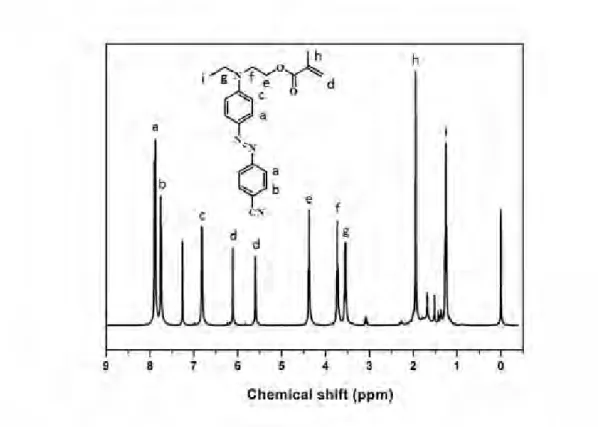
1H NMR spectrum of pure product NABP is showed in Fig. 2-4,
1H NMR (δ, CDCl
3): 8.32 (2H, d), 7.91 (4H, t), 6.80 (2H, d), 3.89 (2H, m), 3.63 (2H, m), 1.56 (2H, s), 1.26 (3H, t) ppm.
Fig. 2-4
1H NMR spectrum of NABP
30
p-Cyanoaniline was diazotized with sodium nitrite in 18% hydrochloride solution at 0~5
oC. The mixture was then added drop wise to N-ethyl-N-(2-hydroxyethyl) aniline in concentrated hydrochloride solution, then neutralized by saturated sodium acetate solution. The deep red precipitate was collected and washed several times with water. Recrystallization from ethanol gave the product, yield 89%.
1H NMR spectrum of pure product CABP is showed in Fig. 2-5.
1H NMR (δ, CDCl
3): 7.87 (4H, m), 7.76 (2H, d), 6.82 (2H, d), 3.89 (2H, m), 3.61 (2H, m), 3.45 (2H, m), 1.25 (3H, t) ppm.
Fig. 2-5
1H NMR spectrum of CABP
p-Methoxyaniline was diazotized with sodium nitrite in 18% hydrochloride
solution at 0~5
oC. The mixture was then added drop wise to
N-ethyl-N-(2-hydroxyethyl) aniline in concentrated hydrochloride solution, then
neutralized by saturated sodium acetate solution. The deep red precipitate was collected and washed several times with water. Recrystallization from ethanol gave the product, yield 85%.
1H NMR spectrum of pure product MABP is showed in Fig. 2-6,
1H NMR (δ, CDCl
3): 7.82 (4H, t), 6.98 (2H, d), 6.78 (2H, d), 3.87 (3H, s), 3.80 (2H, t), 3.56 (2H, t), 3.48 (2H, m), 1.21 (3H, t) ppm.
Fig. 2-6
1H NMR spectrum of MABP
2.3.1.2 Resultant of azobenzene pigments methacrylate
Pigment and triethylamine in dry methylene chloride were cooled to 0
oC, and
distilled methyacryloyl chloride was added dropwise while stirring, the resulting
mixture was stirred at 0
oC for 1 h then at room temperature for 16 h. The methylene
chloride solution was extracted with water and the crude pigment methacrylate
monomer product was purified by silica gel chromatography eluting with
32
hexane/methylene chloride to afford a red solid, yield 64%.
1H NMR spectrum of pure product NABPMA is showed in Fig. 2-7,
1H NMR (δ, CDCl
3): 8.32 (2H, d), 7.91 (4H, t), 6.82 (2H, d), 6.10 (1H, s), 5.59 (1H, s), 4.38 (2H, m), 3.72 (3H, t), 3.54 (2H, t), 1.94 (3H, s), 1.26 (3H, t) ppm.
Fig. 2-7
1H NMR spectrum of NABPMA
Pigment and triethylamine in dry methylene chloride were cooled to 0
oC, and
distilled methyacryloyl chloride was added dropwise while stirring, the resulting
mixture was stirred at 0
oC for 1 h then at room temperature for 16 h. The methylene
chloride solution was extracted with water and the crude pigment methacrylate
monomer product was purified by silica gel chromatography eluting with
hexane/methylene chloride to afford a red solid, yield 59%.
1H NMR spectrum of pure
product CABPMA is showed in Fig. 2-8,
1H NMR (δ, CDCl
3): 7.87 (4H, d), 7.75 (2H, d), 6.80 (2H, d), 6.10 (1H, s), 5.59 (1H, s), 4.38 (2H, t), 3.73 (2H, t), 3.55 (2H, m), 1.94 (3H, s), 1.26 (3H, t) ppm.
Fig. 2-8
1H NMR spectrum of CABPMA
Pigment and triethylamine in dry methylene chloride were cooled to 0
oC, and
distilled methyacryloyl chloride was added dropwise while stirring, the resulting
mixture was stirred at 0
oC for 1 h then at room temperature for 16 h. The methylene
chloride solution was extracted with water and the crude pigment methacrylate
monomer product was purified by silica gel chromatography eluting with
hexane/methylene chloride to afford a red solid, yield 61%.
1H NMR spectrum of pure
product MABPMA is showed in Fig. 2-9,
1H NMR (δ, CDCl
3): 8.83 (4H, d), 6.97 (2H,
d), 6.78 (2H, d), 6.10 (1H, s), 5.8 (1H, t), 4.35 (2H, m), 3.87 (3H, s), 3.69 (2H, t), 3.50
34
(2H, m), 1.94 (3H, s), 1.25 (3H, t) ppm.
Fig. 2-9
1H NMR spectrum of MABPMA
2.3.1.3 Physical properties of side chain polymers made by Free Radical Polymerization
Three different substituent group side-chain azobenzene polymers, including nitro, cyano, methoxyl substituent, were synthesized through Free Radical Polymerization.
The copolymerizations were carried out in a different mole ratio of MMA/ABPMA
from 95/5 to 75/25 in dioxane solvent to get a serious PMMA-co-ABPMA, under
nitrogen atmosphere at 65
oC in the presence of 1 wt% of 2,2′ -Azobis-isobutyronitrile
(AIBN) for 24 h. The resulting copolymer solutions were cooled, precipitated in
methanol, filtered and finally dried under reduced pressure overnight. The polymers
physical properties are showed in Table 3-1.
Table 2-1 Characterization of polymers
Chromophore desity
(mol%)
Chromophore desity b
(wt%)
Mn d
(k) Mw d
(k) PDI d
Tg a
(oC) Td a
(oC) λmax c
(nm)
PMMA-co-NABPMA5 5 14.4 21 27 1.28 110 263 471
PMMA-co-NABPMA15 15 30.8 13 20 1.46 106 268 472
PMMA-co-NABPMA25 25 47.2 14 22 1.63 103 270 471
PMMA-co-MABPMA5 5 13.1 12 13 1.61 110 258 407
PMMA-co-MABPMA15 15 32.2 14 20 1.53 104 252 407
PMMA-co-MABPMA25 25 44.7 15 26 1.72 114 254 408
PMMA-co-CABPMA5 5 13.0 14 20 1.47 103 265 443
PMMA-co-CABPMA15 15 31.5 16 27 1.74 101 259 444
PMMA-co-CABPMA25 25 44.3 13 21 1.59 105 260 443
PMMA — — 29 34 1.90 104 255 —
a
Thermogravametric analysis (TGA) and differential scanning calorimetry (DSC) were performed using an SII-TG/DTA 6200 instrument under a nitrogen atmosphere at a heating rate of 5 °C /min.
b
UV absorption spectra were recorded using a Shimadzu UV–vis spectrometer 1240.
c
Electro-Optic (EO) coefficient measured at 1.31μm, unit of r
33is pm/V, unit of PE is (nm/V)
2.
d
The molecular weights (Mw) and polydispersity (PDI) of the polymers were determined by size-exclusion chromatography (SEC) using a Shodex GPC K-804L column on a JASCO LC2000 liquid chromatography system with CHCl
3as the eluent. This system was calibrated using a narrow PDI Shodex SM-105 polystyrene standards.
2.3.1.4 Physical properties of side chain polymers made by RAFT
Follow the previous work, I used Reversible Addition-Fragmentation Chain
Transfer Polymerization (RAFT) to prepare three different substituent group side-chain
36
azobenzene polymers, including nitro, cyano, methoxyl. RAFT is a kind of controlled polymerization, so it will get more ideal polymers. The monomer MMA, ABPMA and RAFT agent in a mole ratio of 200/1/1 was dissolved in nitrogen degassed anhydrous toluene and stirred at room temperature. The initiator 1 wt% 2,2'-azobisisobutyronitrile (AIBN) was added. The mixture was stirred at room temperature for one hour and at 65
oC for 24 hour under nitrogen atmosphere. The resulting polymer solution was precipitated from methanol three times, and finally dried at 60
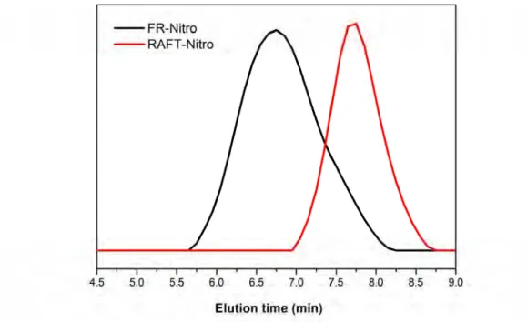
oC under reduced pressure overnight. And at the same time, free radical polymerization also been taken in the same feed ratio as compare. Fig. 2-10~ Fig. 2-12 show the GPC trace of side chain polymers with nitro, cyano, methoxyl substituent, red lines are made from RAFT and black line are prepared from free radical polymerization (FRP). All the polymers made through RAFT have obvious narrow PDI.
Fig. 2-10 GPC trace of nitro substitution polymer using FR and RAFT
Fig. 2-11 GPC trace of cyano substitution polymer using FR and RAFT
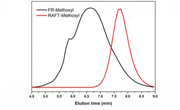
Fig. 2-12 GPC trace of methoxyl substitution polymer using FR and RAFT
From the GPC data of these three polymers, Mn are nearly 40,000, PDI are around
38
2.00 using the first way, and Mn are 10,000, PDI are around 1.30 using RAFT, all react conditions are 24 hours, toluene as solvent, 65
oC. The polymers made from RAFT get narrow PDI, but the molecular weight are low, this because the feed ratio of monomer MMA and RAFT agent are low, though increase the molecular weight through enhance the feed ratio of monomers and RAFT agent. The molecular weights (Mw) and polydispersity (PDI) of the polymers were determined by size-exclusion chromatography (SEC) using a Shodex GPC K-804L column on a JASCO LC2000 liquid chromatography system with CHCl
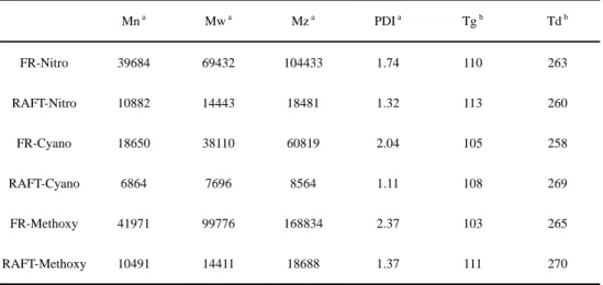
3as the eluent. This system was calibrated using a narrow PDI Shodex SM-105 polystyrene standards. All the definite physical data are showed in Table 2-2.
Table 2-2 Physical properties of polymers prepared both from FR and RAFT
Mn a Mw a Mz a PDI a Tg b Td b
FR-Nitro 39684 69432 104433 1.74 110 263
RAFT-Nitro 10882 14443 18481 1.32 113 260
FR-Cyano 18650 38110 60819 2.04 105 258
RAFT-Cyano 6864 7696 8564 1.11 108 269
FR-Methoxy 41971 99776 168834 2.37 103 265
RAFT-Methoxy 10491 14411 18688 1.37 111 270
a
The molecular weights (Mw) and polydispersity (PDI) of the polymers were determined by
size-exclusion chromatography (SEC) using a Shodex GPC K-804L column on a JASCO LC2000
liquid chromatography system with CHCl
3as the eluent. This system was calibrated using a narrow
PDI Shodex SM-105 polystyrene standards.
b
Thermogravametric analysis (TGA) and differential scanning calorimetry (DSC) were performed using an SII-TG/DTA 6200 instrument under a nitrogen atmosphere at a heating rate of 5 °C /min.
2.3.2 EO properties
Three different substituent group side-chain azobenzene polymers, including nitro, cyano, methoxyl substituent, were synthesize through free radical polymerization.
These side chain polymers were used as host and C1 as guest accomplished binary chromophore system, to measure the EO coefficients by Teng-Man measurement at 1310nm. All the data are listed in Table 2-3. We have found that an optimum PMMA-co-CABPMA
5contained a 5 mol% cyano substituent on the azobenzene moiety and furthermore that the r
33was maximized by incorporation of 15 wt% of C1 chromophore into the polymer host. In this ideal system a high r
33of 63 pm/V was achieved.
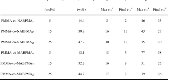
Table 2-3 EO coefficient of side chain polymers preparing by Free Radical Polymerization
Chromophore desity
(mol%)
Chromophore desity a
(wt%)
none guest chromophore guest C1
Max r33 b Final r33 b Max r33 b Final r33 b
PMMA-co-NABPMA5 5 14.4 3 2 46 35
PMMA-co-NABPMA15 15 30.8 16 13 43 27
PMMA-co-NABPMA25 25 47.2 30 12 35 20
PMMA-co-MABPMA5 5 13.1 13 5 77 58
PMMA-co-MABPMA15 15 32.2 16 8 51 25
PMMA-co-MABPMA25 25 44.7 17 2 39 26
40
PMMA-co-CABPMA5 5 13.0 13 2 103 63
PMMA-co-CABPMA15 15 31.5 14 3 41 17
PMMA-co-CABPMA25 25 44.3 26 5 35 23
PMMA — — — — 33 20
a
UV absorption spectra were recorded using a Shimadzu UV–vis spectrometer 1240.
b
Electro-Optic(EO) coefficient measured at 1.31 μm, unit of r
33is pm/V, unit of PE is (nm/V)
2.
Three different substituent group side-chain azobenzene polymers, including nitro, cyano, methoxyl substituent, have also been optimized through RAFT. Size-exclusion chromatography (SEC) trace shows Mw 14k, PDI under 1.3 with THF as the eluent.
From the polymers themselves have been optimized on controlling the molecular weight and PDI, but the physical properties didn't change through this way, Tg and Td are 110
oC and 260
oC similar as the side chain polymer gotten from Free Radical Polymerizations. And using cyano substituent side chain polymer get from RAFT accomplished with 15 wt% C1 the maximum r
33is 120 pm/V, final r
33is 65 pm/V.
Figure. 2-13 to Figure. 2-16 show the conditions during poling about sample which is cyano substituent side chain polymer getting from RAFT and accomplished with 15 wt% C1 chromophore.
In a general experiment, the sample was fixed on the poling stage and the
temperature was increased in several minutes up to around Tg. The poling field was
then applied to the sample at a ramping rate 8 V/min. During the poling process, the
electric current was monitored to optimize poling efficiency and to control local
electrical breakdown in the films. As shown in Figure. 2-15, the current grew rapidly with the ramping of poling field, and maximized at 205 μA when the poling field climbed to 165 V/μm. Generally, the breakdown of the electric field through the polymeric film is accompanied by an abrupt overflow of the electric current. Thus, the ramping of the poling field ceased and maintained at 165 V/μm and temperature rise to 110
oC, when the second increasing trend of the current flow appeared in Figure.
2-15. The current dropped slowly after peaking, and even the poling field maintained a constant value. Figure. 2-16 indicates that the r
33varied simultaneously with the applied voltage and reached its maximum of 120 pm/V at the poling filed of 165 V/μm. The sample was then cooled to room temperature with the poling field maintained. During the rapid cooling process, there was a notable relaxation phenomenon of the molecular ordering as the total EO signal deceased by 45%.
Eventually, r
33of 65 pm/V was realized at room teperature for the poled EO film after
removing the poling field.
42
Fig. 2-13 Typical poling process on cyano substituent side chain polymer get from RAFT as host 15 wt% C1 as guest, Temperature are plotted during the poling process.
Fig. 2-14 Typical poling process on cyano substituent side chain polymer get from RAFT as
host 15 wt% C1 as guest, applied field are plotted during the poling process.
Fig. 2-15 Typical poling process on cyano substituent side chain polymer get from RAFT as host 15 wt% C1 as guest, flowing current are plotted during the poling process.
Fig. 2-16 Typical poling process on cyano substituent side chain polymer get from RAFT as
host 15 wt% C1 as guest, r
33are plotted during the poling process.
44
2.4 Conclusions
Nine azobenzene side chain polymers were prepared through Free Radical Polymerization which containing three different pendent azobenzene moieties, nitro, cyano, methoxy. The chemical structures of the nine azobenzene derivatives were confirmed by NMR, UV absorption and the GPC traces. These polymers displayed a large molecular weight Mw 20 k, PDI 1.3 ~ 1.7, and glass transition temperature of nearly 110
oC. The macroscopic electro-optic coefficients of these polymer were measured using Teng-Man measurement at 1310nm. We have found that an optimum PMMA-co-CABPMA
5contained a 5 mol% cyano substituent on the azobenzene moiety and furthermore that the r
33was maximized by incorporation of 15 wt% of C1 chromophore into the polymer host. In this ideal system a high r
33of 63 pm/V was achieved.
Three different substituent group side-chain azobenzene polymers, including nitro, cyano, methoxyl substituent, have been optimized through RAFT. Size-exclusion chromatography (SEC) trace shows Mw 14k, PDI under 1.3 with THF as the eluent.
From the polymers themselves have been optimized on controlling the molecular
weight and PDI, but the physical properties didn't change through this way, Tg and Td
are 110
oC and 260
oC similar as using Free Radical Polymerizations gotten the side
chain polymers. And using cyano substituent side chain polymer get from RAFT
accomplished with 15 wt% C1 the maximum r
33is 120 pm/V, final r
33is 65 pm/V.
2.5 References
[1] Y. Shi, C. Zhang, H. Zhang, J. H. Bechtel, L. R. Dalton, B. H. Robinson, and W.
H. Steier. J. Science. 199 (2000) 288.
[2] M. Lee, H. E. Katz, C. Erben, D. M. Gill, P. Gopalan, J. D. Heber, and D. J.
McGee. J. Science. 298 (2002) 1401.
[3] L. R. Dalton, P. A. Sullivan and D. H. Bale. J. Chem. Rev. 110(1) (2010) 25.
[4] X. Piao, X. Zhang, S. Inoue, S. Yokoyama, H. Miki, I. Aoki, A. Otomo, H.
Tazawa. J. Organic Electronics. 12 (2011) 1093-1097.
[5] X. Piao, X. Zhang, Y. Mori, M. Koishi, A. Nakaya, S. Inoue, I. Aoki, A. Otomo, S.
Yokoyama. J. Journal of Polymer Science: Part A: Polymer Chemistry. 49 (2011) 47-54.
[6] X. Zhang, I. Aoki, X. Piao, S. Inoue, H. Tazawa, S. Yokoyama, A. Otomo. J.
Tetrahedron Letters, 51 (2010) 5873-5876.
Chapter 3 The Synthesis and Characterization of Electro-Optic Material Based on Novel Polymer Brush
3.1 Introduction
Organic second-order nonlinear optical (electro-optic, EO) materials represent a potentially transformative technology around which next generation computing, telecommunications, sensing, medical/security imaging, and other industries may be constructed. Binary chromophore system EO materials which are made up of chromophore containing polymer matrix and guest chromophore in simple guest-host system represent a recently developed class of EO materials that shows great promising. Compared to their individual components, the remarkably large EO activity displayed by binary chromophore material systems, is thought to arise from one important effect, the increased glass transition temperature and molecular weight of the dipolar chromophore containing polymer matrix may enhance the macroscopic EO coefficients of the binary chromophore EO material systems.
Cylindrical polymer brush possessing densely grafted side chains on a linear
polymer main chain, ideally every monomer unit of the main chain carries one side
chain [1]. This type of structure has also been given the very intuitive name molecular
bottlebrush. Cylindrical polymer brushes are interesting because of the expectation
that their unique structure may result in unusual properties [2]. Because of the regular
48
multibranched structure, they have the following characteristics in comparison with the corresponding linear polymers of the same molecular weight: (1) a small and compact molecular dimension, (2) an extended wormlike conformation resulting from the steric repulsion between densely grafted side chains, and (3) many chain ends per molecule enhancing the chain-end effects [3].These virtues of polymer brushes may enhance the Tg of polymer matrix, improve the loading density of chromophore, and increase chromophore regular arrangement. Our major effects have been focused on developing chromophore containing polymer brush to use as polymer matrix in binary chromophore EO materials.
Three main strategies for preparing molecular brushes: grafting through [4][5]—
the polymerization of macro monomers, grafting onto [6][7]— the addition of previously prepared side chains to a backbone, and grafting from [ 8 ]— the polymerization of side chains from a macroinitiator backbone.
Fig. 3-1 Three main strategies for preparing molecular brushes: grafting through, grafting onto, and grafting from.
Grafting from has received much attention recently as a new pathway for the
preparation of well-defined cylindrical polymer brushes. This technique is based on the growth of side chains from polymeric backbone bound initiating groups. With the grafting from method, cylindrical polymer brushes with high grafting density and well defined backbones and side chains have been prepared. In particular, the purification of the resulting polymer brush is much simpler in comparison with the other two methods because the resulting polymer brush is the only polymeric product [9].
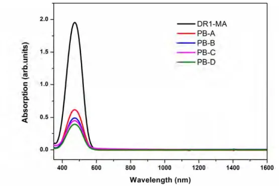
In this report, nonlinear optics azobenzene polymer brushes were synthesized as
the following steps: (1) the synthesis of a well defined macro initiator, PBIEM, by the
esterification of poly(2-hydroxyethyl methacrylate) (PHEMA), which was
synthesized via RAFT of silyl-protected HEMA; (2) ATRP of MMA, Disperse Red 1
Methacrylate (DR1-MA) initiated by the pendant α-bromoester groups of PBIEM,
yielding cylindrical brushes with PMMA and PDR1-MA side chain. Well defined
polymer brushes were confirmed by gel permeation chromatography (GPC) and
nuclear magnetic resonance spectroscopy (
1H NMR). Mn of the polymer brush are
around 2,000k, narrow PDI 1.30~1.34, Tg =120
oC. The macroscopic EO coefficient
of these polymer brushes are nearly 5 pm/V using Teng-Man measurement, indicating
through ATRP can get chromophore containing polymer brush to use in binary
chromophore EO materials as polymer matrix.
50
3.2 Experimental details
3.2.1 Materials
2-Cyanopropan-2-yl-4-fluorobenzodithioate (CPFDB) was prepared according to the literature [10]. CuBr was prepared according to the literature [11]. Anisole was stirred over CaH
2overnight and distilled under reduced pressure. Tetrahydrofuran (THF) was distilled over CaH
2prior to use. 2-Bromoisobutyryl bromide (98%, Aldrich), N,N,N′,N″,N″-pentamethyldiethylenetriamine (PMDETA, 99%, Aldrich), and other reagents were commercialized chemicals and used as received. Potassium fluoride, tetrabutylammonium fluoride and trimethylchloro silicane were bought from Tokyo Chemical Industry Co., LTD and used without further purification. Monomer methylmethacrylate (MMA) was distilled under reduced pressure with drier CaH
2. Methylene chloride was stirred over CaH
2overnight. Triethylamine was dried by KOH.
2-Hydroxyethyl methacrylate (HEMA), magnesium sulfate (MgSO
4), 2,2′-Azobis-isobutyronitrile (AIBN, 99%, Aldrich), Methanol, cyclopentanone and hexane commercialized solvents and used as received.
3.2.2 Measurements
Thermogravametric analysis (TGA) and differential scanning calorimetry (DSC)
were performed using an SII-TG/DTA 6200 instrument under a nitrogen atmosphere at
a heating rate of 5
oC /min. DSC was performed using a SII-DSC 6220 under a nitrogen
atmosphere at a heating rate of 5
oC /min. The molecular weights (Mw) and polydispersity (PDI) of the polymer brushes were determined by size-exclusion chromatography (SEC) using a Shodex GPC K-804L column on a JASCO LC2000 liquid chromatography system with CHCl
3as the eluent. This system was calibrated using narrow PDI Shodex SM-105 polystyrene standards. UV absorption spectra were recorded using a Shimadzu UV–vis spectrometer 1240.
3.2.3 Synthesis of HEMA-TMS
Dry HEMA (40 mL, 0.33 mol), NEt
3(78 mL, 0.56 mol) and 600 mL dehydrate ether were added in 1000 mL flask, after well-distributed trimethylchloro-silicane (52 mL, 0.41 mol) splash into slowly at 0
oC, then warm to room temperature, stirred 12h.
The resulted crude product was filtered then dissolved in ether and washed by water three times, following dried by MgSO
4. Reduced pressure distillation get the final product. Monomer conversion was determined by the
1H NMR spectrum, synthesis route as shown in Scheme 3-1.
Scheme 3-1 Schematic illustration of the synthesis of HEMA-TMS
3.2.4 Synthesis of P(HEMA-TMS)
Bulk polymerization of HEMA-TMS was performed in a sealed ampule equipped
52
with a stir bar under vacuum. A typical procedure was as follows: CPFDB (13.8 mg, 5.8×10
-2mmol), AIBN (1.9 mg, 1.2×10
-2mmol) and HEMA-TMS (14.0 g, 69.3 mmol) were added into a 20 mL glass ampule, dehydrate THF as solvent. The mixture was degassed through four freeze-evacuate-thaw cycles, and then the ampule was sealed under vacuum.
The polymerization was carried out in an oil bath at 90
oC for 1 h. The reaction was terminated by cooling reaction the mixture with an ice bath. The resulted crude product was purified by precipitating into a large amount of methanol and water mixture (7:3 volume ratio) three times. Monomer conversion was determined by the
1