多翼ファンの空力特性と騒音に関する実験的研究
(シュラウドの影響)
佐々木壮一
*・黒田晃伸
**・林秀千人
*An Experimental Study of Aerodynamic Characteristics and Noise of a Forward Curved Fan (Influence of Shroud)
by
Soichi SASAKI*, Akinobu KURODA** and Hidechito HAYASHI*
In this study, influence of shroud on aerodynamic characteristics and noise of a forward curved fan has been estimated by the performance test of an actual machine. Moreover, influence of unsteady internal flow on broadband noise in the low frequency domain has been analyzed by the numerical simulation. The static pressure of the forward curved fan with shroud (MF9S) became high than that of the fan without shroud (MF9). The maximum efficiency of MF9S was increased 1.6% than MF9 due to the improvement of the static pressure. On the other hand, the fan noise of MF9S at the maximum efficiency point became approximately 1 dB larger than MF9 due to the influence on the broadband noise in the vicinity of the 200 Hz. The stalled cell was formed at the front side of the impeller of MF9; the cell was rotated around the impeller with 40% rotation speed of the impeller. The cell formed seven pseudo blades around the impeller. It has clarified that the broadband noise in the low frequency domain is generated at the vicinity of the frequency which is rotation speed of the stalled cell.
Key words: Rotating Stall, Turbomachinery, Aerodynamic Noise, Computer Fluid Dynamics
1.はじめに
多翼ファンの舌部隙間と羽根枚数との設計条件が 最適化されると,舌部での干渉騒音を広帯域騒音レベ ルまで低減させることができる(1-2).従って,送風機全 体のシステム設計やファンの運転条件次第では,この ファンから発生する実質的な空力騒音は広帯域騒音 になる.著者らの研究グループでは,実機の多翼ファ ンから発生する比較的低周波の領域における広帯域 騒音がファン騒音の主因となる事を実機の性能試験 と定常流れの数値シミュレーションによって確認し ている(3).また,いくかの羽根車の設計条件の内,こ のファンの空力特性は羽根車の前面側にシュラウド を付加することによって改善されることを実験的に
確認している(4).しかし,多翼ファンから発生する空 力騒音に及ぼすシュラウドの影響については不明な 点も多く,この設計条件下における低周波域の広帯域 騒音と非定常の流れとの関係について詳細に解析さ れた先行研究は少ない.本研究では,多翼ファンの空 力特性と騒音に及ぼすシュラウドの影響を実機の性 能試験によって評価する.低周波数の領域における広 帯域騒音に及ぼす内部流動の影響が非定常の数値シ ミュレーションに基づいて考察されている.
2.実験装置および測定方法
図1は性能試験に用いられた供試羽根車を示したも のである.表1にその主要寸法が整理されている.多
平成23年 6月17日受理
* システム科学部門(Division of System Science)
** 生産科学研究科博士前期課程(Graduate School Student, Graduate School of Science and Technology)
翼ファンの羽根車の翼形状には,二次元前向き羽根が 採用されている.羽根車の外径は 125mm,翼弦長は
9mm,羽根枚数は40枚,スパン長さは50mmである.
以下の説明では,シュラウドのない羽根車をMF9と呼 び,シュラウドを有す羽根車をMF9Sと称す.
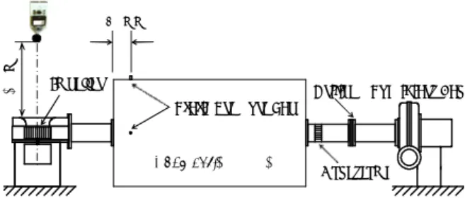
図2は実験装置の概略図を示したものである.羽根 車の回転数は2800rpmに設定されている.ファンの静 圧は一辺が500mm,全長900mmのプレナム室内で測 定されている.ファンの空力特性は式(1)の無次元量で 整理されている.
2 , , 60 2
3 2
U b D
L
U b D Q U
Ps
π
(1)ここで,ψ は静圧係数,ρ は空気密度,Psはファンの 静圧,φは流量係数,Qは流量,λは軸動力係数,Dは 羽根車外形,bはスパン長さ,Uは羽根車の周速度,L は軸動力,η は効率である.ファン騒音は精密騒音計
(ONO SOKKI, LA4350) によって計測され,その振 動 の 電 気 信 号 が FFT ア ナ ラ イ ザ (ONO SOKKI, CF5210)によって周波数分析される.尚,ファン騒音 の測定の際には,補助ファンとチャンバーが実験装置 から取り外されている.このとき,ファンの流量はあ らかじめ測定されたファンの静圧特性に基づいて出口
側のダンパーで調整される.
図3は流れの数値計算に用いられたモデルを示した ものである.(a)がCADモデルであり,(b)が計算格子 である.ファン全体の格子は約450万要素で構成され ており,二種類のファン全体の非定常流れが解析され ている.ファンの入口境界には作動点の流量が与えら れており,出口境界には大気圧の条件が与えられてい る.流れの数値シミュレーションでは,羽根車が二回 転する定常の乱流場が標準k - εモデルによって予備計 算され,その流れ場が非定常計算の初期条件として与 えられている.非定常の流れ場はLESによって計算さ れ,その流れ場が2000回の繰り返し計算によって発達 させられている.最小格子幅には,翼の後縁に発達す (a) MF9 (b) MF9S
Fig. 1 Test impeller
Table 1 Main dimensions of test impeller MF9S MF9
Impeller
1 Thickness , t (mm)
with shroud without shroud
Shroud
Outer diameter ,D (mm) 125
Chord length , C(mm) 9
Number of blades , B 40
Span length , L (mm) 50
MF9S MF9
Impeller
1 Thickness , t (mm)
with shroud without shroud
Shroud
Outer diameter ,D (mm) 125
Chord length , C(mm) 9
Number of blades , B 40
Span length , L (mm) 50
Impeller
Static Pressure Tap
Subsidiary Fan
Honeycomb Orifice
1.0 m
Chamber ; □900×500 80 mm
Chamber;□500×900
Fig. 2 Experimental apparatus
(a) CAD model
(b) 2D mesh of the fan
Fig. 3 Model for computer fluid dynamics
る乱流境界層を解析することが可能な格子幅が設定さ れている.
3,実験結果および考察
図 4 は多翼ファンの空力特性を示したものである.
実測値の MF9S の静圧は,広い流量の範囲に渡って MF9のより高い.この静圧係数の上昇に伴って,MF9S のファン効率はMF9よりも僅かに改善される.本研究 の範囲では,CFDの静圧係数は実測値と同程度の圧力 になった.以下の解析では,二つの羽根車の非定常の 空力音源が流量係数φ=0.1の作動点で解析されている.
図5では二種類の多翼ファンの騒音特性が比較され ている.シュラウドを有すMF9Sの騒音レベルが,シ ュラウドのない MF9 よりも全ての流量域において高 い.また,いずれもファン騒音はおよそ φ=0.1 から φ=0.2まで増加する.図6は作動点(φ=0.1)における ファン騒音のスペクトル分布を比較したものである.
MF9Sの全帯域騒音レベルはMF9よりも約1dB(A)大き くなる.両者のファ ン騒音のスペ クトル分布には ,
200Hz近傍で差が生じていることがわかる.
図7には,Powell-Howeの音源項を可視化した分布 が示されている.解析の断面位置は後面シュラウドか ら35mmの位置である.Powell-Howeの音源項は式(2) によって定義される(5).
1000 500 1000 5000
20 40 60
LA, dB(A)
f , Hz
MF9 ( 64.3 dB ) MF9S ( 65.3 dB ) φ = 0.1
N = 2800rpm Z = 40
Fig. 6 Spectrum distribution of aerodynamic noise
Main Flow
N= 2800 rpm φ = 0.1
(a) MF9S
Main Flow
N= 2800 rpm φ = 0.1
(b) MF9
Fig. 7 Visualization on aerodynamic sound source of Powell-Howe
0 0.1 0.2 0.3 0.4
0 1 2 3
0 20 40 60 80
ψ
ψs,λ η
N = 2800rpm Z = 40 MF9 (EFD, without shroud) MF9S (EFD, with shroud)
η
η
λ ψs
MF9 (CFD) MF9S (CFD)
Fig. 4 Aerodynamic characteristics
0 0.1 0.2 0.3 0.4
60 70 80
LA , dB(A)
φ
MF9 (without shroud) MF9S (with shroud) N = 2800rpm
Z = 40
φ=0.1
Fig.5 Noise characteristics
u div p
t c p
a a
0 2
2 2 2
(2)
ここで,右辺の は渦度ベクトル,uは速度ベクトル
である.空間的な音源の分布を式(2)の右辺の音源項に よって可視化することができる.いずれの羽根車にも,
翼間に強い空力音源が生成されている.(a)のMF9Sの 場合,その翼間に正負交互の一様な空力音源が生成さ れている.一方,(b)の MF9 では,翼間に生成される 音源はMF9Sよりも弱くなり,翼間には羽根車の周方 向に非一様な分布が形成される.
図8は羽根車周りの絶対速度の分布を速度ベクトル で示したものである.(a)のMF9Sの速度分布には羽根 車の外向きに流出する一様な速度分布が形成される.
一方,(b)のMF9の場合,図 7で示された弱い音源の 位置では外向きの流れがなく,羽根車周りの速度分布 は非一様になる.ここでは便宜上,MF9に形成される 失速した領域をセルと呼ぶことにする.この計算では,
時間間隔が羽根車の1ピッチ(9.15 mm)の移動を約
10分割する時間に設定されている.従って,流れが100 サイクル計算されると,翼は約10ピッチ移動すること になる.しかし,解析の対象となるセルは100サイク ル後に約4ピッチ分しか移動しなかった.従って,そ のセルは羽根車の回転速度の約 40%で失速しながら 旋回していると考えられる.セルの回転周波数は式(3) によって見積もることができる.
60 / NZ
f (3)
ここでNは低圧領域の回転速度(rpm),Zは羽根車の周 方向に形成されるセルの数である.セルの旋回速度は 羽根車回転数の約40%である.また,その失速セルは 6枚の羽根車の翼毎に一つのセルを形成していること から,羽根車の周方向には約7つのセルが形成されて いると考えられる.式(3)に基づけば,この旋回失速す るセルの回転周波数は約130Hzとなる.
図9はMF9の子午面の流れを速度ベクトルで示した ものである.(a)がセルの形成されていない位置(O-A
Main Flow
N= 2800 rpm φ = 0.1
(a) MF9S
Main Flow
Cell O
N= 2800 rpm φ = 0.1
B
A
(b) MF9
Fig. 8 Velocity distribution in 2-dimentional section
(a) O-A section (b) O-B section
Fig. 9 Velocity distribution in meridional section
Fig. 10 Pressure distribution around the impeller
断面)での流動様相であり,(b)がセルの形成されてい る位置(O-B断面)での流動様相である.いずれも後 面側では外向き流れの主流部が形成され,この流れが 実質的な送風機の流れになる.(a)のO-A断面での流動 様相には,羽根車の前面側の小さな渦状の再循環流が 形成されている.一方,(b)の失速セルが形成さている 位置では,この渦状の再循環流の領域が形成されてお らず,その主流部の範囲が狭くなっている.図10には MF9の羽根車周りの圧力分布が示されている.羽根車 の前面側に低圧の領域が形成されている.これは正圧 面側から負圧面側への漏れ渦によって形成されるもの であると考えられる.この漏れ渦によって外向きの流 れが阻害され,失速セルが形成されると考えられる.
4.おわりに
シュラウドを有す多翼ファン(MF9S)の静圧は,シュ ラウドのない多翼ファン(MF9)よりも高くなった.
これに伴い,MF9Sの最高効率はMF9よりも1.6%改善 された.MF9の前面側には失速セルが形成され,この セルは羽根車回転数の約40%の速度で失速しながら旋 回する.このセルは羽根車の周方向に疑似的な7枚の 動翼を形成した.多翼ファンの低周波側の広帯域騒音 は,このセルの旋回失速の回転周波数近傍で発生する
ことを明らかにした.
謝辞:実験に協力をいただい平成22年度卒業生の北村 拓也君に謝意を表す.
参考文献
1) 佐々木壮一, 林秀千:遠心羽根車の後流と円柱と の干渉によって発生する離散周波数騒音に関する 研究(第1報:離散周波数騒音の発生メカニズム), 長崎大学工学部研究報告, 40(74), pp.1 - 6, 2009.
2) 佐々木壮一, 林秀千:遠心羽根車の後流と円柱と の干渉によって発生する離散周波数騒音に関する 研究(第2報:干渉騒音の予測), 長崎大学工学部 研究報告, 40(74), pp.7 - 12, 2009.
3) 佐々木壮一, 黒田晃伸:翼ファンの空力音源に及 ぼす舌部隙間流れの影響, 長崎大学工学部研究報 告, 41(76), pp.7-12, 2011.
4) 北村拓也,佐々木壮一:多翼ファンの内部流れと 広帯域騒音に関する研究,日本機械学会九州学生 会講演論文集,pp.99-100, 2011.
5) M. S. Howe, Theory of Vortex Sound, Cambridge University, 2003