小型プロペラ風車の出力特性と広帯域騒音に関する研究
佐々木壮一*・鈴木康太**・坂田涼**
Study of Output Characteristics and Broadband Noise of a Micro Propeller Wind Turbine
by
Soichi SASAKI*, Kota SUZUKI** and Ryo SAKADA**
In order to clarify the influence of the flow regime around the impeller on the broadband noise in the high frequency domain generated by a micro propeller wind turbine, the flow around the impeller was solved by the numerical simulation. Furthermore, the output characteristics and the aerodynamic noise of the turbine were measured by a wind tunnel. From comparison in the free torque condition, the noise of the tip speed ratio 12 became 7.6 dB larger than the noise of the tip speed ratio 8.2 due to the broadband noise in the high frequency domain. Because the flow was separated at the vicinity of the leading edge from the hub side to mid-span, the aerodynamic noise was concentrated at the leading edge, whereas the noise source of the blade tip side concentrated to the trailing edge side because the flow was attached to the blade. These results indicate that these perturbations in the high frequency domain become one of the important factors for the broadband noise source of the wind turbine.
Key words: Wind Turbine, Aerodynamic Noise, Wind Energy
1.はじめに
小型の水平軸プロペラ形風車には,災害時の非常用 電源,電気自動車の供給電源,離島や山岳地帯におけ る電源など,その風車固有の役割がある.また,平成 24年7月から実施されている再生可能エネルギー固定 買取制度の対象にもなるため,スマートグリッドの電 源としても期待されている.しかし,定格運転される この風車の空力騒音は 80dB 以上になり,その普及に は騒音の問題を克服することが一つの課題となる.
大型の風車から 発生する騒 音の課題で は低周波 音 の問題が採り上げられるが(1),この種の騒音は小型の プロペラ風車から発生する空力騒音の主因とは異なる.
Fleig らは(2-3),地球シミュレータを用いた大規模シミ
ュレーションによって風車の空気力学的な性能と音響
放射を予測し,反曲線の翼端形状が高周波数領域の音 圧レベルを減少させることに効果があることを明らか にした.Arakawaら(4)は,圧縮性LESを用いた風車周 りの流れ場と音場の解析によって翼後縁に集中した双 極子型の空力音源を可視比し,反曲線の翼端形状が空 力騒音を低減させるメカニズムを明らかにした.この ような翼の後縁から発生する空力騒音,即ち,後縁騒 音に関する初期の解析モデルはAmietやHoweによっ て1970年代に研究されている(5-6).これらの研究では,
翼の前縁を無視した半無限翼が取り扱われており,翼 後縁の散乱過程が翼弦長よりも十分に小さいことが仮 定されている.一方.Michel Roger とStephan Moreau
はAmietの後縁騒音モデルを有限な翼弦長のモデルに
拡張し(7),高周波数帯域の広帯域騒音が後縁騒音と密
平成25年12月17日受理
* システム科学部門(System Science Division)
** 総合工学専攻(Department of Advanced Engineering)
接に関係することを示した(8).また,この解析モデル が遠心ファンや軸流ファンなどに応用され,ファンの 広帯域騒音を高精度に予測できることが示されている
(9-10).しかし,プロペラ風車の広帯域騒音と後縁騒音
の関係について議論された研究は少なく,特に,小型 のプロペラ風車から発生する実測値の広帯域騒音の性 質に基づいて後縁騒音の影響を詳細に解析した先行研 究はほとんどない.
本研究では,小型のプロペラ形風車から発生する高 周波数帯域の広帯域騒音に及ぼす羽根周りの流れの影 響が議論される.実機のマイクロプロペラ風車の出力 特性と騒音が風洞で測定され,一様流速によって回転 させられる羽根車周りの流れが数値シミュレーション によって再現されている.その数値シミュレーション の翼面上の圧力変動量の解析に基づいて,高周波数帯 域の広帯域騒音と後縁騒音の関係が考察されている.
おもな記号 A;受風面積(m2)
C;翼弦長(m) Cp;出力係数 f;周波数(Hz)
LA;騒音レベル(dB(A)) R;羽根車半径(m) T;トルク(N m) u;周速度(m/s) V;主流風速(m/s) v;絶対速度(m/s) w;相対速度(m/s) wz;軸方向相対速度(m/s) w∞;理論相対速度(m/s) λ;周速比
ξ;翼の前縁からの距離(m) ω;角速度( rad/s )
ρ;密度(kg/m3)
2.実験装置および測定方法
図1には,性能試験の対象となるプロペラ風車の外 観が示されている.表1は風車の仕様を整理したもの である.この風車はサウス ウエスト ウインド パワー
社のAir 403を改造したものである.羽根車の直径は
1170mm,羽根枚数は3枚,発電機の定格出力は400W
(12V)である.性能試験装置のナセルには反動トル クを与えるための三相電動機(三菱電機;SF-JR)と トルク計(小野測器;SS-020)が取り付けられており,
実機の出力係数を計測することができる.羽根車の回 転数は光電式回転計によって計測される.
図2は吸い込み型風洞の概略図を示したものである.
測定胴の断面は一辺1.8m の正方形であり,その全長 は5.0m である.羽根車を回転させるための十分な一 様流速を得るために ,集合胴と測 定胴の間には直 径 1.2m の絞り機構が設けられている.風洞内の主流風 速は,軸流送風機の回転数をインバータにより制御す ることで調整される.風車の出力特性は式(1)の周速比 λと出力係数Cpによって定義される.
V R ,
3 2 AV
CP T (1)
ここで,Rは羽根車の半径(m),ωは角速度(rad/s),V は主流速度(m/s),Tはトルク(N m),ρは空気密度
(kg/m3),Aは風車の受風面積(m2)である.空力騒音
は羽根車の回転中心から1m上流の位置で1/2インチ マイクロホンが取り付けられた精密騒音計(小野測 器;LA4350)によって計測される.騒音計からの出力 信号はFFTアナライザ(小野測器;CF5210)へ入力さ れ,その空力騒音が周波数分析される.
Motor Torque Meter
Electrical Generator
Impeller
Fig. 1 Micro propeller wind turbine
Table 1 Specifications of the wind turbine Diameter of Impeller 1170 mm
Number of Blades 3
Specific Power 400 W
Initial Velocity
(for rotation) 1.51 m/s
Initial Velocity
(for power generation) 3.58 m/s
Torque Meter Ono-Sokki SS-020 (2.0 Nm)
図3には,数値シミュレーションで使用された風車 のモデルが示されている.数値シミュレーションには
CradleのSCRYU/Tetraが用いられている.計算条件は
表2に示される通りである.本研究では,風車翼周り の流動解析の第一歩として,風車全体の流れ場が約 150万要素の格子で構成されている.乱流モデルには SST k-ωモデルが採用されている.入口境界の質量流 量は風車の流入風速が実測値と等しくなるように11.7 kg/sに設定されており,出口境界には大気圧の条件が
与えられている.風車羽根車周りの非定常の流れ場が スライディングメッシュによって解析される.
3.実験結果および考察
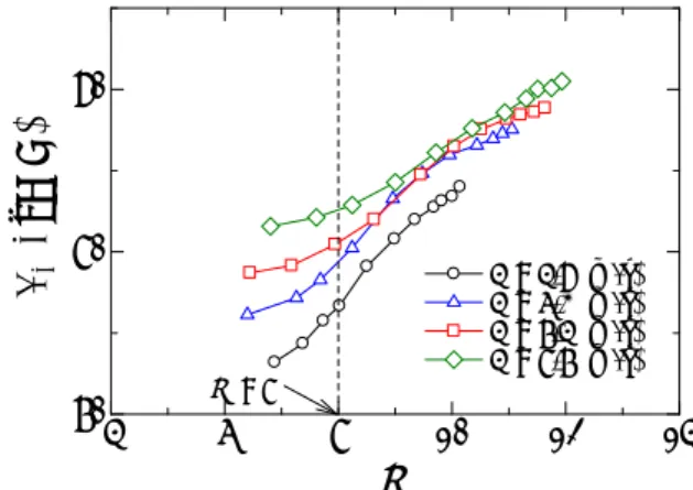
図 4 は周速比と出力係数の関係を主流風速毎に比較 したものである.主流風速が 7.4m/s 以上になると,出 力係数は周速比 8 近傍で最大となる.主流速度 8.7m/s のとき,無拘束条件における周速比は約 12 になる.図
2600
φ1200 φ1000
2200 5000
1800 1500
1230 1000
□1800×1800
Collector Measurement Part
Nozzle Variation
System Axial
Fan
Partition
Fig.2 Wind tunnel
inlet
outlet
wall rotate impeller
main flow
Fig. 3 Model for CFD
Table 2 Summary of the numerical simulation Number of Elements 1,490,166
Turbulent Model SST k-ω Inlet Boundary Q = 11.7 [kg/s]
Outlet Boundary Ps = 0 [Pa]
Time Step 3.125×10⁻⁵
cycle 2048
Flow Unsteady
4 6 8 10 12 14
0 0.1 0.2 0.3
λ
v = 4.9 (m/s) v = 6.2 (m/s) v = 7.4 (m/s) v = 8.7 (m/s)
Cp
λ = 8
Fig. 4 Relationship between the tip speed ratio and the power coefficient
4 6 8 10 12 14
70 80 90
LA, dB(A)
λ
V = 4.9 (m/s) V = 6.3 (m/s) V = 7.4 (m/s) V = 8.7 (m/s) λ = 8
Fig. 5 Relationship between the tip speed ration and the noise level
5 には,周速比と空力騒音の関係が示されている.周 速比 8 近傍では,主流速度が速いほど風車の騒音レベ ルが大きくなる.一方,無拘束条件近傍では(λ=12), 主流速度に応じた騒音レベルの違いは小さくなる.
図 6 には,風車から発生する空力騒音のスペクトル 分布を異なる運転条件で比較したものが示されている.
図中の破線は風洞の暗騒音である.図(a)の主流風速の 比較では,主流風速 8.7m/s の空力騒音が 350Hz(低周 波 域 ) に お け る 離 散 周 波 数 騒 音 の 影 響 で 主 流 風 速 7.4m/s の騒音よりも 1.7dB 大きくなる.一方,図(b) の無拘束状態における騒音レベルの比較では,周速比 12 における騒音が 1000Hz(高周波域)のオーダーにお け る 広 帯 域 騒 音 の 影 響 で 周 速 比 8.2 の 騒 音 よ り も 7.6dB 大きくなる.以下の解析では,図(b)の高周波数 領域の広帯域騒音の空力音源について議論する.
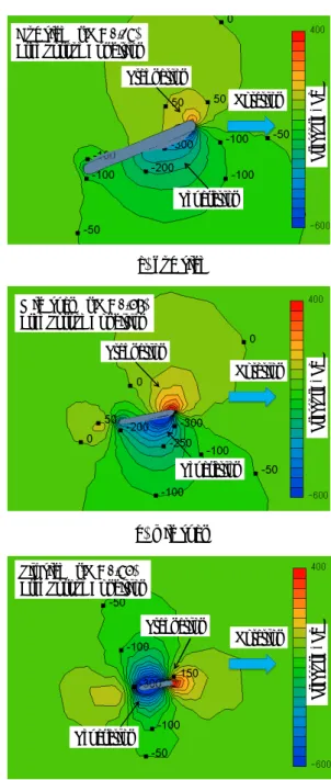
図 7 は羽根車周りの瞬時の圧力分布を可視化したも のである.主流は紙面の上から下に向かって流れてお り,羽根車は左から右に回転する.図 7(a)のハブ側で は,主流が翼の前縁側で淀むために圧力が高くなって
いる.羽根車の前縁側の圧力は,はく離の影響で負圧 になっている.図 7(b)のスパン中央では,翼の周速度 が速くなるために,よどみ点の圧力も高くなっている.
また,翼弦長が短くなるために,前縁はく離した領域 が翼弦長全体に分布している.図 7(c)の翼先端近傍で は,負圧の領域が翼の後縁側で左右対称に形成されて いる.翼先端近傍ではその周速度が高速になるために 翼周りの流れは付着した流れとなる.従って,翼周り
Hub side ( r/R = 0.28) Free Torque Condition
Rotation
Pressure , Pa
Stagnation
Separation
(a) hub side
Mid span ( r/R = 0.57) Free Torque Condition
Rotation
Pressure , Pa
Stagnation
Separation
(b) mid span
Tip side ( r/R = 0.85) Free Torque Condition
Rotation
Pressure , Pa
Stagnation
Separation
(c) tip side
Fig. 7 Distribution of the instantaneous pressure around the blade
102 103 104
20 30 40 50 60 70 80
f , Hz LA , dB(A)
V = 8.7 m/s ( 90.5 dB ) V = 7.4 m/s ( 88.8 dB ) V = 7.4 m/s, BGN ( 75.0 dB ) λ=12
(a) Main flow
102 103 104
20 30 40 50 60 70 80
λ = 11.9 ( 90.5 dB ) λ = 8.2 ( 82.9 dB ) BGN ( 77.9 dB )
LA , dB(A)
f , Hz
V = 8.7 (m/s)
(b) Tip speed ratio
Fig. 6 Spectral distribution of the aerodynamic noise
の流れは前縁はく離せず,その流れはハブ側とスパン 中央のものとは異なる様相となる.
図 8 は翼の負圧面側の翼面上における圧力変動の分 布を示したものである.スパン中央における流れは前 縁はく離をするために,その圧力変動が翼の前縁に集 中している.一方,翼先端側の圧力変動は翼の後縁に 集中した構造となる.数値シミュレーションの結果に よれば,スパン中央における翼前縁近傍の周速度は,
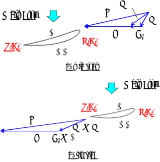
その相対速度の約3倍であった.この場合,主流風速 は翼周りの流れに影響を及ぼすために,その流れは前 縁はく離する.このとき,翼の前縁側での流れは滑り 速度Csで滑るために,前縁はく離した流れの領域は不
安定になる(図 9(a)参照).一方,翼先端近傍では,
周速度が主流風速と比較して非常に高速になる.この 場合,流れは翼の後縁近傍まで沿うために,すべり速 度が小さくなる(図 9(b)参照).従って,羽根先端側 では翼後縁近傍の境界層内部の擾乱が広帯域騒音の一 つの原因になると考えられる.
4.おわりに
(1) 本実験の対象となる小型のプロペラ風車では,主 流風速が 7.4m/s 以上になると,その出力係数は周 速比 8 近傍で最大となった.周速比 8 近傍では,
主流速度が速いほど風車の騒音レベルが大きく なった.
(2) 主流風速 8.7m/s の空力騒音は 350Hz で発生する離 散周波数騒音の影響で主流風速 7.4m/s の騒音よ りも 1.7dB 大きくなった.一方,無拘束状態にお ける騒音レベルの比較では,周速比 12 における騒 音が高周波数の領域における広帯域騒音の影響で 周速比 8.2 の騒音よりも 7.6dB 大きくなった.
(3) ハブ側からスパン中央における流れは翼の前縁で はく離をするために,その圧力変動が翼の前縁に 集中して形成される.一方,翼端側の圧力変動は 翼の後縁に集中した後縁騒音の構造を呈す.これ らの擾乱によって発生する高周波の変動が小型の プロペラ風車から発生する広帯域騒音を形成する 因子になると考えられる.
参考文献
(1) 二井義則,五反田哲朗,松宮煇,河村俊次,小川 利訓,土屋敬一,山田佐佳,猪股登,アップウィ ンド型風車の低周波音,日本音響学会誌,Vol. 52, No. 5 (1996), pp. 341-347.
(2) Fleig Oliver, 飯田誠,鈴木正己,荒川忠一,LES 大規模計算による風車翼の流れと騒音予測 : 第 1 報,単独翼実験データとの検証,日本機械学会論 文集B編,Vol. 71, No. 701 (2005), pp. 177-183.
(3) Fleig Oliver, 飯田誠,荒川忠一,LES大規模計算に よる風車翼の流れと騒音予測 : 第2報, 翼端に 着目した風車翼の空力騒音低減について,日本機 械学 会 論文 集B 編,Vol. 71, No. 701 (2005), pp.
183-190.
(4) Chuichi Arakawa, Oliver Fleig, Makoto Iida1 and Masakazu Shimooka, Numerical Approach for Noise Reduction of Wind Turbine Blade Tip with Earth Simulator, Journal of the Earth Simulator, Vol.
2(2005), pp. 11–33.
0 0.5 1
0 100 200 300 400
ξ/C ,( - ) Σp' (fi) , Pa
tip side mid span hub side Free Torque condition
V = 8.65 [m/s]
L. E. T. E.
Fig. 8 Distribution of the pressure fluctuation on the blade chord
u
Main Flow w
T.E. L.E.
w∞ v
cs P.S.
S.S.
(a) mid span
T.E. L.E.
u
w∞≒w v
cs≒0
P.S.
S.S.
Main Flow
(b) tip side
Fig. 9 Schematic view of the flow regime around the blade
(5) R. K. Amiet, Noise due to Turbulent Flow Past a Trailing Edge, Journal of Sound and Vibration, Vol.
47, No.3 (1976), pp. 387–393.
(6) M.S. Howe, A Review of the Theory of Trailing-edge Noise, Journal of Sound and Vibration, Vol. 61, No.3 (1978), pp. 437–465.
(7) M. Roger, S. Moreau, Back-scattering Correction and Further Extensions of Amiet’s Trailing Edge Noise Model. Part I: Theory, Journal of Sound and Vibration, Vol. 286 (2005), pp. 477–506.
(8) S. Moreau, M. Roger, Back-scattering Correction and Further Extensions of Amiet’s Trailing Edge Noise Model. Part II: Application, Journal of Sound and Vibration, Vol. 323 (2009), pp. 397-425.
(9) Sanjose, M., et al., Unsteady Numerical Simulation of a Low-speed Radial Fan for Aeroacoustic Predictions, Proc. of ISRMAC14, Honolulu, No.1117 (2012), USB (10) J. Christophe, et al.: Uncertainty Quantification of Low-speed Axial Fan Self-noise, Proc. of ISRMAC14, Honolulu, USB, No. 1142 (2012), USB