A Study on Shape and Stiffness of Membrane Structure Due to Warp of Membrane Device
Rikushi Kato, Osamu Mori, Toshihiro Chujo, Yasutaka Satou, Nobukatsu Okuizumi, and Hiroaki Tsunoda
The technique of solar power sail was demonstrated by the IKAROS mission. However, at the same time, unexpected phenomena were confirmed. The membrane surface of IKAROS has deformed to a not flat shape. In the shape change of the film surface, it is known that the whole membrane surface changes greatly like an umbrella shape or a saddle shape depending on the warping direction of the thin film device. Objection of this study is to clarify mechanism of influence on solar radiation pressure torque due to warp of membrane device and its solution method. Therefore, the shape of the overall membrane surface is clarified by using a simple FEM model and the SRP torque with respect to the shape is calculated, and the mechanism of the overall shape change in warpage and its influence is clarified.
膜面デバイスの反りによる膜構造物の膜面形状と剛性に関する研究
ソーラー電力セイルの技術はIKAROSによって実証された.しかしそれと同時に予期せぬ現象が確認された.
IKAROS の膜表面は平面ではない形状に変形していることがわかった.膜面の形状変化は,薄膜デバイスの反
り方向によって膜面全体が傘状や鞍状に大きく変化することがわかっている.本研究の目的は,膜装置の反り による太陽光圧トルクへの影響のメカニズムとその解法を明らかにすることである.
INTRODUCTION
In recent years, because it is lightweight and storage efficiency is good, membrane structures are attracting attention for use in space. The solar power sail “IKAROS”, launched by JAXA in 2010, succeeded in various missions in space and demonstrated solar power sail for the first time in the world. Solar sail deploys its sail in space, and receives sunlight, it propels using solar light pressure. In IKAROS, high power was gained by attaching a thin film solar cell to the film surface.
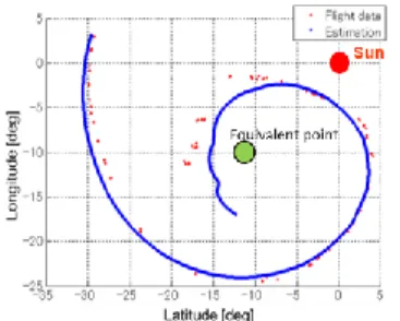
Solar power sail technique was demonstrated in the IKAROS mission. However, unexpected phenomena were confirmed. From the flight data, it was confirmed that the rotation axis of the solar sail was spin motion rather than circular movement. This phenomenon was considered to be caused by deformation of the membrane surface of IKAROS. As a cause of this, the influence of warping of the thin film solar cell was considered. Because the so-lar sail’s thin film solar cell is a multi-layer film structure, it is considered that it was influenced by warping from bimetallic effect. It is thought that the warping of thin film solar cell by bimetallic effect caused change in the entire film surface.
Figure 1. IKAROS spin axis flight data.
PREVIOUS RESEARCH
In previous studies, shape change due to warping of the
membrane and effects of shape change on SRP torque have been carried out easily. From this, it is known that the whole membrane surface changes greatly like an umbrella shape or a saddle shape depending on the warping direction of the thin film solar cell. Also, it is understood that this is related by positive or negative of circumference margin. The condition of this research was deformation in the membrane surface as a whole. In this research, we analyzed cases where the length in the tangential direction and the length in the radial direction were shortened.
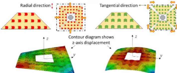
Firstly, when there is warping in the tangential direction, the circumference becomes shorter. Therefore, circumference margin is negative, and the membrane escapes down be-cause the membrane tries to go inside but cannot enter. As a result, the overall membrane surface transforms into an umbrella like shape.
Secondly, when there is warping in the radial direction, the radius becomes shorter. Therefore, circumference margin is positive and at that time, petal edges hit each other. As a result, membrane escapes up and down and the overall membrane surface transforms into a saddle like shape.
However, the condition of this research is focused on when the over-all membrane surface is warped and out-of-plane deformation is not considered.
Figure 2. The membrane surface shape by circumference margin length
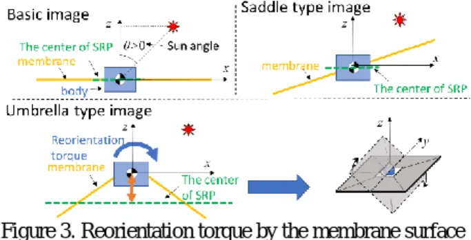
Next, the membrane surface shape and the SRP torque will be described. Solar sails have reorientation torque and windmill torque depending on the membrane surface shape.
Reorientation torque is occurring around the y axis. This is caused by the difference between the center of SRP and the centroid. As can be seen in Figure 3, in the basic image with a flat membrane model, there is no difference between the center of SRP and the centroid. In the saddle shape, the membrane is deformed upwards and downwards, so the average does not change. Therefore, reorientation torque is not generated in these cases. However, umbrella type is different. Because in the umbrella type the whole membrane surface is deformed downwards, the difference between the center of SRP and the centroid occurs. As a result, reorientation torque is more largely generated. This reorientation torque affects the spin axis motion.
Figure 3. Reorientation torque by the membrane surface shape.
Windmill torque occurs around the x axis. This is caused by the changing of shape. It occurs when the membrane surface is deformed into a wind turbine like shape and force is applied obliquely to the membrane surface as shown in Figure 4. The windmill torque affects the spin speed and direction. For this reason, shape change affects SRP torque.
Figure 4. Effect of torque by windmill type OBJECTIVE AND APPROACH
Objection of this study is to clarify mechanism of influence on solar radiation pressure torque due to warp of membrane device and its solution method. Accordingly, the shape of the overall membrane surface is clarified by using a simple FEM model and the SRP torque with respect to the shape was calculated, and the mechanism of the overall shape change in warpage and its influence was clarified.
The condition of the previous research was that the overall membrane surface is warped and out-of-plane deformation was not considered. Therefore, in addition to the cases so far, it is necessary to evaluate types other than the overall membrane surface warped, like types considering out-of- plane deformation. Therefore, objection of this study is that the location, the direction and the stiffness of the warped device are used as parameters, and to clarify the shape that warped device gives to the overall membrane surface and identify the effect caused by it. From the results, we will consider the case with the least influence of SRP torque. For that reason, the shape of the overall membrane surface is clarified by using a simple FEM model. And calculating the SRP torque with respect to the shape, clarifying the mechanism of the overall shape change in warpage and its influence is also done in this re-search.
ANALYSIS MODEL AND CONDITION
For convenience of calculation cost, we analyzed with a simple FEM model. The analysis model consists of 4 petals, warped cell, tether and bridge. For each petal, warped cells are affixed at equal intervals. Warped cells are composed of two layers for convenience of analysis because devices reproduce the warped state. The conditions are shown in table 1.
Figure 5. Analysis model by FEM.
Table 1. Analysis model condition.
Base film
One side Thickness
220[mm]
20[μm]
Warped cells
Thickness(1st) (2nd) Curvature Curvature radius
25[µm]
15[µm]
0.0557[/mm]
17.963[mm]
Bridge Length 0.21[mm]
In this study, the membrane surface stiffness is changed by the number of cells. The low membrane stiffness model widens the interval between cells. The high membrane stiffness model narrows the interval between cells. In this paper the location of warpage is shown as in Figure 7.
Figure 6. Examples of differences in stiffness.
Figure 7. Example showing the warped location.
The solar light pressure torque is evaluated as follows. We aligned the axis as shown in Figure 8 and defined the solar direction θ [deg]. In this study, we assumed that the sun is in the x-z plane. The average of the light pressure torque when the object rotated 360[deg] was obtained. To see the effect of reorientation torque and windmill torque, we set the solar direction to θ = 10 [deg]. In this case there is little torque around the x axis. Torque around y-axis is reorientation torque and torque around z-axis is windmill torque.
Figure 8. Calculation model of SRP torque.
EVALUATION OF SHAPE ANALYSYS
For the case of the umbrella and saddle shape, the influence of the SRP torque is evaluated. Case 1 is when space between devices are wide, and when membrane stiffness is low. When warped in the radial direction, the radius becomes shorter and transforms to a saddle type shape. When warped in the tangential direction, the
circumference becomes shorter and transform to a umbrella type shape. In these cases, SRP reorientation torque around y-axis torque, are 2.53×10⁻⁴[µNm] for the saddle type and 5.41×10⁻⁴[µNm] for the umbrella type. The torque is smaller for the saddle type than the umbrella type.
Therefore, the saddle type is considered to be an ideal shape because there is only a little influence by SRP torque.
Figure 9. Analysis result of case 1.
Next, we will consider case2. Case2 is when space between devices are narrow and the membrane stiffness is high. In this case as well, the shape becomes an umbrella type and a saddle type. In this case 2, SRP reorientation torque is 4.14×10⁻⁴[µNm] for the saddle type and 11.5×10⁻⁴[µNm]
for the umbrella type. Therefore, reorientation torque is smaller for the saddle type than the umbrella type as in case 1.
Figure 10. Analysis result of case 2.
Now, look at the cross section of saddle type shown in Figure 11. Case1 is warped only at the cell location, but case2 is warped as a whole. Therefore, low membrane stiffness shows local deformation, and high membrane stiffness shows global deformation. Reorientation torque of case 1 is 2.53×10⁻⁴[µNm] and case 2 is 4.14×10⁻⁴[µNm].
The reorientation torque for case 2 is bigger than case 1. As a result, the saddle type is considered to be an ideal shape with little influence of SRP torque. However, global deformation is not preferable because have large influence on both types.
Figure 11. The cross section of case 1 and 2.
These saddle and umbrella type deformations can also be confirmed with other models. Even if the outermost circumference warps by little, or if the center warps by little, it will be of the same type. Therefore, irrespective of the magnitude of the warp, it can be seen that it deforms into umbrella or saddle type depending on whether the circumference margin is positive or negative.
Figure 12. Analysis result of other cases.
Next, consider a model in which radial and tangential direction warp are mixed. In the case of Figure 13, the model is warped more largely in the tangential direction than the radial direction. The model forms a umbrella shape.
The shape is determined by the sign of circumference margin. On the other hand, as shown in Figure 14, consider the case where the location like Figure 13 warps but the membrane surface stiffness is high. This model is also warped more largely in the tangential direction than in the radial direction. However, the membrane surface is deformed to a saddle type. This is caused by global and local deformation depending on membrane surface stiffness.
A cross-sectional view of each mem-brane surface stiffness is shown in Figure 15. Similar to the case where the overall mem-brane surface of Figure 11 warps, global deformation occurs with radial warpage. Because the global deformation increases the warps of the membrane surface. Therefore, by global deformation in the radial direction, it exceeds the amount of warpage in the circumferential direction, so it becomes a saddle shape rather than an umbrella shape.
When the membrane surface stiffness is high, it becomes easy to become a saddle shape due to global deformation.
Figure 13. Analysis result of mixed direction with low membrane stiffness model.
Figure 14. Analysis result of mixed direction with high membrane stiffness model.
Figure 15. Cross-sectional view of warped location.
RADIAL DIRECTION WARPED SHAPE CASE We evaluated the radial direction warped shape case.
Case3 is warped only at the outer-most circumference and case4 is warped only at the center line. The results are shown in Figure 16. Reorientation torque of Case 3 was 1.93×10⁻⁴[µNm] and for case 4 was 5.25×10⁻⁴[µNm]. As a result, reorientation torque was smaller in case 3 compared to case 4. This is related to the stiffness of petal edge. Warping of the film surface increases stiffness.
Therefore, edge of case 3 is high in stiffness but edge of case 4 has low stiffness. In the Saddle type the petal edge push against each other. The high stiffness membrane surface, like case 3, can withstand and not bend. Therefore, less influences of SRP torque. However, in the low stiffness membrane surface, like case 4, cannot withstand and will bend. There-fore, more influences by SRP torque.
Figure 16. Analysis result of case 3 and case 4.
Figure 17. Deformation image of edge.
Next, we considered case 5. Case 5 is increasing the cell location on outermost circumference, and the edge stiffness
is higher than case 4. Therefore, case4 could not withstand and bend, but case 5 can withstand and not bend. These results are shown in Figure 18. Re-orientation torque of case 5 was 4.28×10⁻⁴[µNm]. Therefore, it is considered that improvement was made by increasing the stiffness of the outermost circumference because reorientation torque is smaller than case 4. As a result, the torque can be suppressed by giving stiffness by warping the outermost circumference.
In conclusion, in the case of radial direction warped shape, the outermost circumference is deformed, which influences the torque. Therefore, the torque can be suppressed by giving stiffness by warping the outermost circumference.
Figure 18. Analysis result of case4 and case 5.
Table 2. Analysis result of radial direction warped shape case.
Case No. Reorientation torque[µm]
Case 3 1.93×10⁻⁴ Case 4 5.25×10⁻⁴ Case 5 4.28×10⁻⁴
TANGENTIAL DIRECTION WARPED SHAPE CASE Next, we evaluated the radial direction warped shape case.
As before, case 3 is warped only at the outermost circumference and case 4 is warped only at the center line.
These results are shown in Figure 19. And, reorientation torque for Case 3 was 3.96×10⁻⁴[µNm] and for case 4 was 13.77×10⁻⁴[µNm]. As a result, reorientation torque was smaller for case 3 than case 4. This is related to warped device location. Firstly, we will consider a warped at the edge model. The warped location tries to enter inside because there is not enough circumference at the warped location. However, it cannot be done because there is originally a membrane. Therefore, this location deforms downwards. In this way, it will transform into a umbrella shape. On the other hand, in the case of warped at the center, likewise, the warped location tries to enter inside but does not. Therefore, this location deforms downwards by the same amount. Therefore, the edge of the membrane deforms more largely downwards. The difference between the center of SRP and the centroid increases. As a result, the influence of SRP becomes larger.
Figure 19. Analysis result of case 3 and case 4.
Figure 20. Deformation image of the membranes surface.
Next, we will consider case 5. As explained before, case 5 is when the cell location on outermost circumference is increased, and the edge stiffness is higher than case4. The results are shown in Figure 21. Reorientation torque of case 5 was 1.29×10⁻⁴[µNm]. This is related to the return of the shape due to the increase in the stiffness of the outermost circumference. If outermost circumference is high in stiffness, this location will try to move up because there is surplus length like the saddle type. But the warped location deforms downwards. Therefore, the shape becomes like Figure 22. This transformation decreases deformation and the distance between center of SRP and centrode. As a result, reorientation torque is smaller than the low stiffness case.
In conclusion, in the case of tangential direction warped shape, the outermost circumference is deformed, which influences the torque. Therefore, the torque can be suppressed by giving stiffness by warping the outermost circumference.
Figure 21. Analysis result of case4 and case5
Figure 22. Deformation image of the membranes surface.
Table 3. Analysis result of tangential direction warped shape case.
Case No. Reorientation torque[µm]
Case 3 3.96×10⁻⁴
Case 4 13.77×10⁻⁴
Case 5 1.29×10⁻⁴
CONCLUSION
The following is stated from the results so far. Firstly, the solar sail has a reorientation torque due to the height difference between the center of SRP and the centrode. That is, it has a reorientation torque depending on its shape. And the shape of the solar sail changes as the membrane surface warps. This is divided into two types according to the warp direction, that is, the circumference of the circumference.
Secondly, in the case of membrane surface warped in the radial direction, the membrane surface shape transforms into a saddle type. The saddle shape is less influenced by SRP torque. And, When the stiffness of the outermost circumference stiffness is low, the deformation increases, and the reorientation torque becomes larger. If the stiffness of the mem-brane is high, global deformation will occur and torque will increase.
Thirdly, in the case of membrane surface warped in the tangential direction, the mem-brane surface shape transforms into an umbrella type. The umbrella shape has a big influence. However, when the stiffness of the outermost circumference stiffness is high, the de-formation decreases which results in decrease of reorientation torque.
In conclusion, based on result so far, the worst type, or the
type with the most influence from SRP torque, was when the warped direction is tangential direction, and outermost circumference stiffness is low. The best type, or the type with the least influence of SRP torque, was when warped direction is in the radial direction, and when the stiffness of the membrane is low, and stiffness of the outermost circumference is high.
REFERENCE
1) Hiroyuki KINOSHITA, Osamu MORI, Nobukatsu OKUIZUMI and Hiroaki TSUNODA, “Evaluation of IKAROS Membrane Shape Considering Curve and Bending Stiffness of Thin-film Devices”, JSASS,Vol.17,pp.29-34,2018
2) O. Mori, Y. Shirasawa, Y. Mimasu, Y. Tsuda, H.
Sawada, T. Saiki, T. Yamamoto, K. Yonekura, H.
Hoshino, J. Kawaguchi and R. Funase, “Overview of IKAROS Mission,” Advances in Solar Sailing, Part I, pp.25-43, 2014
3) Jun MATSUMOTO, Go ONO, Toshihiro CHUJO, Kosuke AKATSUKA and Yuichi TSUDA, “FEM- based High-fidelity Solar Radiation Pressure Analysis”, Trans. Japan Soc, Aero, Space Sci. Vol. 60, No.5, pp.
276-283, 2017.