高能率エンドミル
MEC 型シリーズ
High efficient MEC end mill series
高能率エンドミル
High efficient MEC end mill
MEC型
MECH型 先端交換式MECH型
MECH Head Exchangeable Type
MECX型
● MEGACOAT NANO PR1535追加
MEGACOAT NANO PR1535 is now available
● 先端交換式MECH型登場! !
MECH Head Exchangeable Type is now available
● MEC型エンドミル モジュラータイプ追加
Modular Type of MEC End Mill is added in lineup
MEC型
美麗壁面
Excellent Finished Wall
良好直角
High Squareness
大
Large
小
Small
低
Low
高 テーブル送り
Vf(mm/min)
切込み ap(mm)
High
MECH 型
heavy milling重切削
type
type general
MEC 型
汎用
MECX 型
type小型M/Csmall machines大きな切込みで高能率加工を実現
Long depth of cut enable high efficiency machining
■MEC型シリーズラインナップ MEC end mill series lineup
MECH 型
type 重切削・高能率加工 Heavy milling and High efficient machining■特長
Advantages1.良好な切りくず排出
Improved Chip Evacuation2.高能率加工
Efficient Machining3.低抵抗
Low Cutting Force4.ビビリを抑制
Reduced chattering重切削対応
For heavy milling
他社品A
Competitor AMECH
ホルダフルート部の平カット
により良好な切りくず排出を可能にします。
Flute with flat-cut enables good chip evacuation
被削材 Work Material :SS400 Vc = 120 m/min
ap×ae=40mm×10mm,fz = 0.12mm/t MECH032-S32-11-5-4T
ニック付きチップ
でくい込み時の抵抗 を低減・分散させビビリを抑制し高能率加工 を可能にします。Notched insert reduces cutting force and chattering and enables efficient machining
先端刃へのクーラントホール付き
(エンドミルタイプのみ)
Coolant hole for bottom insert (end mill only)
ニックにより切りくずを細かく分断
Notched insert breaks chips into small pieces
●MEC型シリーズの使い分け
Different useage of MEC end mill series
1
15
10
5
0.08
0.06 0.1 0.15 0.2
推奨切削領域
Recommended cutting range
切削領域 Cutting range
横切込み ae(mm) Width of Cut
1刃当りの送り Feed per Tooth fz(mm/t)
Comp. BB社 C社
Comp. C
MECH
型5000 4000 3000 2000 1000
0 MECH型 他社品D
Comp. D 他社品E
Comp. E
3,580
3,950
4,660
切削抵抗 Cutting Force (N)
MECH型 type
■ ビビリを抑制
Reduced chattering●加工面(側面)比較
Comparison of surface wall
ニック付きチップでくい込み時の抵抗 を低減・分散させビビリを抑制し高送 りを可能にします。
Notched insert lowers and disperses cutting force, and enables high feed rates by reducing Chattering
●ホルダのランニングコスト削減
Cost reduction of toolholder
1)ホルダ先端部(2段切刃まで)が本体から分離 Holder head portion will be separated from the body (by second cutting edge)
2)先端部が破損してもフロントピースだけ交換可能 If holder head is damaged, front piece can be exchangeable.
■ 低抵抗
Low cutting force■ チップ材種にPR1535(MEGACOAT NANO:PVDコーティング)を追加。
PR1535 (MEGACOAT NANO: PVD coated insert) is now available
●MEGACOAT NANO
高硬度(35GPa)と優れた耐酸化性(酸化開始温度1,150℃)が摩耗を抑制し、耐チッピング性能も向上
Prevents wear and fracture with high hardness (35GPa) and superior oxidation resistance (oxidation temperature:1,150℃) 被削材 Work Material:S50C
Vc = 120 m/min ap×ae = 40 mm×5~13 mm fz = 0.06 ~ 0.2 mm/t MECH032-S32-11-5-4T
被削材 Work Material:S50C Vc = 120 m/min ap×ae = 40mm×10 mm fz = 0.1mm/t MECH032-S32-11-5-4T
(当社比較) Internal evaluation
他社品 F Comp.F
被削材 Work Material:S50C Vc=120m/min fz=0.12mm/t ap×ae=40×7mm
(当社比較) Internal evaluation
なめらかな加工面
Smooth surface of shoulder wall
ビビリが生じている
Chattering surface
・切削抵抗比較(主分力比較) Cutting Force (principal force)
・ニック付きチップにより低抵抗 Low Cutting Force due to Notched Inserts
■ 先端交換式MECH型
MECH Head Exchangeable Type
分割構造
Separate structure
組付け状態
Assembled status
ベースユニットはBT50一体型で高剛性
Base unit is high rigidity with BT50 combination
フロントピースは先端側2段で分割
Front piece is separated by second stage of the head.
クランプボルト(HH...)でベースユニットとフロント ピースを固定
Base unite and front piece is fixed by clamp bolt (HH…)
MEC 型
type 高能率エンドミル High efficient end mill■特長
Advantages1.低抵抗、良好な切れ味
Low cutting force and sharp cutting performance
2.良好な直角度、なめらかな 加工壁面
Perfect 90°shoulders, and smooth surface of shoulder wall
3.鋼・ステンレス・鋳鉄・アルミ 等、幅広いワーク材質に対応 する豊富な材種レパートリー
An extensive grade lineup applicable to a wide range of work materials, such as steel, stainless steel, cast iron and aluminum
4.高速M/C用
モジュラータイプ新登場
New Modular Type End Mill for High Speed M/C is now available
剛性・耐久性向上 Higher Rigidity & Durability
…厚いチップ受け部・大きな隅R設計
… Thicker Insert Seat & Larger Chip Pocket Radius
ボディー耐久性向上 Higher Body Durability
…高硬度シルバーコート仕様
…High Hardness Silver Coating クーラントホール付(ø16mmシャンク以上)
Coolant Hole (for Shanks of ø16mm and over) 高強度・長寿命
High Strength & Long Tool Life
…PVDコーティング
…PVD Coating
低抵抗・切れ味良好
Low Cutting Force & Sharp Cutting Performance
…ハイレーキ仕様(A.R.最大+23°)の刃先設計
…High Rake Angle (A.R. Max.+23°) 切りくず排出性向上
Better Chip Evacuation
…大きなチップポケット・
専用ブレーカの採用
…Large Chip Pocket & Specific Chipbreaker
23°
厚いチップ受け部 Thicker Insert Seat
大きな隅R Larger Chip Pocket Radius
● 加工壁面がなめらか Smooth Surface of Shoulder Wall
肩削りにおける多段切込みで、段差の少ないなめらかな加工壁面と良好な 直角度が得られます。
Smoothly finished shoulder wall and high squareness at shouldering with multipul passes
● 直角度が良好 Perfect 90° Shoulders
■加工面の比較 Work Surface Comparison
MEC型エンドミル
MEC type End Mill 他社品G
Comp.G
13µm 18µm 29µm
他社品HComp.H
90°
工具径ø20 S50C Cutting Dia. 20mm / S50C Vc=120m/min,ap×ae=5×10mm fz=0.1mm/t,乾式(外部エアー)
Dry(with compressed air)
(当社評価) Internal evaluation
(当社評価) Internal evaluation
■モジュラータイプの特長
Features of Modular Type End Mill● 低いゲージライン Low gage line
95m m
75mm
30mm 30mmゲージライン
(基準位置)
Gage line (Standard position)
ゲージライン
(基準位置)
Gage line (Standard position)
モジュラータイプはシャンクタイプに比べ、同じ突出し長さにもかかわらず、
刃先からゲージラインまでの距離が短い
Modular type has shorter distance from the cutting edge to the gage line, compared to Shank type, though the overhang length is same.
ビビリが低減できるため、高速 M/C(BT30/BT40 等)でも高能率・高品位加工が可能
High efficiency cutting on high speed M/C (BT30/BT40, etc.) due to the superior anti-chattering performance. High quality cutting is possible.
モジュラータイプ
Modular type シャンクタイプ
Shank type
3
● 刃数の違いによる使い分け
How to select Multi-edge or Less edge toolholder肩加工 Shouldering (a
e=10mm) 溝加工 Grooving
・モジュラータイプ 加工可能条件
Available Cutting Condition of Modular type肩加工は送りを上げ、能率アップが可能な多刃タイプ、
溝加工は切削抵抗を下げることが可能な少数刃タイプが適します。
Choose Multi-edge toolholder for shouldering; higher efficiency in cutting by higher feed rate. For grooving, choose Less edge toolholder to lower cutting force.
多刃が 有利
Choose Multi-edge toolholder
少数刃が 有利
Choose Less edge toolholder
溝加工 Grooving
2 4 6 8
0.1 0.15 0.2 0.25 0.05
ap
fz
肩加工 Shouldering
2 4 6 8
0.1 0.15 0.2 0.25 0.05
ap
fz
2枚刃切削時
Available Cutting Condition for 2-edge
3枚刃切削時
Available Cutting Condition for 3-edge
■よくある質問
Frequently Asked QuestionQ. 二面拘束仕様のアーバは通常の BT 主軸に取り付きますか?
Can the two-face clamping arbor be mounted on a general BT spindle?
A. 取り付きます。二面拘束非対応の主軸の場合には通常の BT アーバとしてお使いいただけます。
Yes. It can be used as a general BT arbor with a general BT spindle.
二面拘束対応主軸に 本アーバを装着した場合
Two-face clamping arbor mounted on two-face clamping spindle
二面拘束非対応主軸に 本アーバを装着した場合
Two-face clamping arbor mounted on general spindle
二面拘束の効果はありませんが、通常の BT アーバとしてお使いいただけます。
It can be used as a general BT arbor, though the advantage of the two-face clamping will not be shown.
スキマあり Clearance スキマなし
No clearance ボディー耐久性向上
Higher Body Durability
…高硬度シルバーコート仕様
…High Hardness Silver Coating
縦切込み(ap) cutting depth (ap)
1刃 送り(fz) feed per tooth (fz)
ap=3(mm)
fz=0.1mm/t
JS JS JT JT
大
Large
小
Small
大
Large
小
Small
MECX 型
type 高能率・低抵抗エンドミル High efficient and low cutting foce end mill■特長
Advantages1.刃数の多い仕様で高能率加工を実現
Efficient machining due to small diameter cutter that holds multiple inserts
2.低抵抗・高強度設計で小型マシンに最適
Recommended for small machines: low cutting force and high strength design
3.汎用JTブレーカと低抵抗JSブレーカで 広範囲な切削領域をカバー
Covers a broad range of applications with the multi-purpose JT chipbreaker and the low cutting force JS chipbreaker
● ブレーカレパートリー
Chipbreaker Lineup低抵抗JSブレーカ
Low cutting force JS Chipbreaker
汎用JTブレーカ
General JT Chipbreaker
●MECXブレーカの使い分け
Selecting chipbreaker図 3 Fig. 3
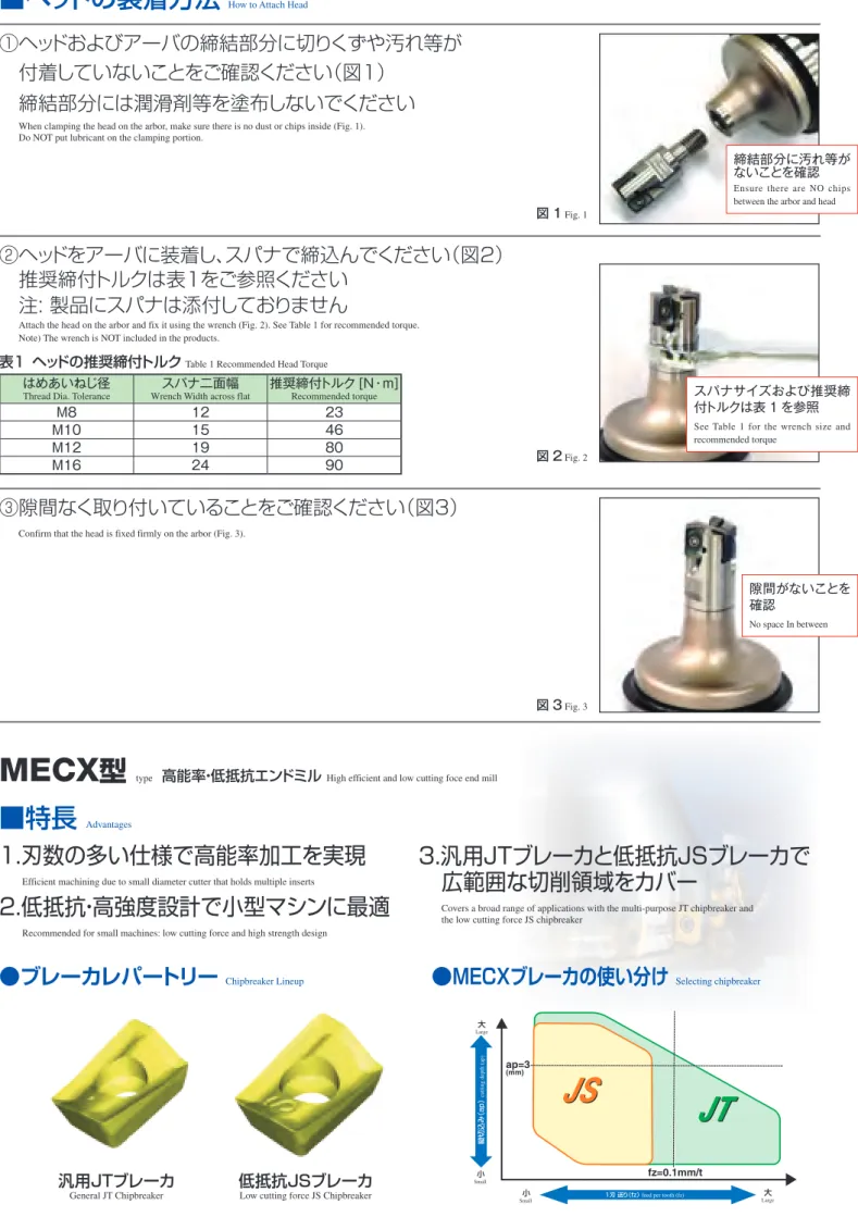
■ヘッドの装着方法
How to Attach Head①ヘッドおよびアーバの締結部分に切りくずや汚れ等が
付着していないことをご確認ください(図1)
締結部分には潤滑剤等を塗布しないでください
When clamping the head on the arbor, make sure there is no dust or chips inside (Fig. 1).
Do NOT put lubricant on the clamping portion.
②ヘッドをアーバに装着し、スパナで締込んでください(図2)
推奨締付トルクは表1をご参照ください
注:製品にスパナは添付しておりません
Attach the head on the arbor and fix it using the wrench (Fig. 2). See Table 1 for recommended torque.
Note) The wrench is NOT included in the products.
③隙間なく取り付いていることをご確認ください(図3)
Confirm that the head is fixed firmly on the arbor (Fig. 3).
表1 ヘッドの推奨締付トルク Table 1 Recommended Head Torque
はめあいねじ径
Thread Dia. Tolerance スパナ二面幅
Wrench Width across flat 推奨締付トルク [N・m]
Recommended torque
M8 12 23
M10 15 46
M12 19 80
M16 24 90
締結部分に汚れ等が ないことを確認
Ensure there are NO chips between the arbor and head
スパナサイズおよび推奨締 付トルクは表 1 を参照
See Table 1 for the wrench size and recommended torque
隙間がないことを 確認
No space In between
図 1 Fig. 1
図 2 Fig. 2
図 3 Fig. 3
5
3.汎用JTブレーカと低抵抗JSブレーカで 広範囲な切削領域をカバー
Covers a broad range of applications with the multi-purpose JT chipbreaker and the low cutting force JS chipbreaker
● MEC/MECX型 レパートリー
Lineup of MEC/MECX1.材種レパートリー(PVDコーティング) Grade Lineup (PVD Coated Insert)
2.ブレーカ・コーナRレパートリー Chipbreaker lineup and Corner Radius variation
形状shape
コーナR(rε)
Coner Radius
型番 Description
コーナR(rε) Coner Radius
0.2 0.4 0.8 1.2 1.6 2.0 2.4 3.1 4.0
汎用JTブレーカ General JT Chipbreaker
BDMT0703…ER-JT ● ● ●
BDMT1103…ER-JT ● ● ●
BDMT11T3…ER-JT ● ● ● ● ● ● ● ●
BDMT1704…ER-JT ● ● ● ● ● ● ● ●
低抵抗JSブレーカ Low cutting force JS Chipbreaker
BDMT0703…ER-JS ● ● ●
BDMT1103…ER-JS ● ● ●
BDMT11T3…ER-JS ● ● ●
BDMT1704…ER-JS ● ●
アルミ用JAブレーカ JA Chipbreaker for Aluminum
BDGT11T3…FR-JA ● ● ●
BDGT1704…FR-JA ● ● ● ●
アルミ用ダイヤモンドチップ PCD for Aluminum
BDMT11T3…FR ● ●
BDMT1704…FR ● ●
3.多様なレパートリー (MEC / MECX型の使い分け) Various products lineup of MEC/MECX(Differrent useage of MEC and MECX)
MECX-07 Type MEC-11 Type MEC-17 Type
BDMT070304ER-JT BDMT11T308ER-JT BDMT170408ER-JT
①刃 数 が 多く、テ ーブ ル 送りが 上 げられ 、 高能率加工が可能
②低抵抗・高強度設計で複合加工機や小型 マシンに最適
①刃長11mmのチップで低抵抗と高強度を両立
②ホルダ強度を確保し、1刃当りの送りを上げ高 能率加工を実現
①刃長17mmチップで大きな切込みが可能
1) Multiple edges, capable of increasing table feed and high efficiency machining
2) Design with low cutting force and high toughness,
1) Actualized low cutting force and high toughness with an insert with 11mm edges
2) Actualized high efficiency machining by ensuring
1) Substantial cut is available with an insert with 17mm edge length
17 11
7
3 枚 刃
3 edges 2 枚 刃
2 edges
MECX25-S25-07-7T MEC25-S25-11T MEC25-S25-17
7 枚 刃
7 edges
・ 鋼用
PR1225
、鋳鉄用PR1210(M EGACOA T)に加え、N i 基耐熱合金/チタン合金/析出硬化系ステンレス鋼用
PR 1535(MEG ACOAT NAN O)をレパートリー
PR1225 for steel, PR1210 for cast iron (MEGACOAT) and PR1535 (MEGACOAT NANO) for Ni-base heat resistant alloy, titanium alloy and precipitation-hardened stainless steel
MEGA C OA T N AN O
・高硬度(35GPa)と優れた耐酸化性(酸化開始温度1,150℃)が摩耗を抑制し、
耐チッピング性能も向上
Prevents wear and fracture with high hardness (35GPa) and superior oxidation resistance (oxidation temperature: 1,150°C)
■ CVDコーティング
CVD Coated Carbide
・ マルテンサイト系ステンレス鋼/Ni基耐熱合金用CVDコーティング
C A6 53 5をレパートリー
CA6535 for martensite stainless steel and Ni-base heat resistant alloy
酸化開始温度 Oxidation temperature (℃)
硬度 Hardness (GPa)
10 400 TiCN
TiAIN
MEGACOAT
MEGACOAT NANO
TiN
600 800 1000 1200 1400
15 20 25 30 35 40
耐酸化性 Oxidation Resistance 高
低 High
Low
●適合チップ Applicable Insert
使用分類の目安 Guidance of usage choice 炭素鋼・合金鋼 Carbon Steel・Alloy Steel
■ ★ ★
適合ホルダ参照ページ Ref. to Page for Toolholder
★:荒加工/第1推奨(★:Roughing/First Choice)
☆:荒加工/第2推奨(:Roughing/Second Choice)
■:仕上げ/第1推奨(■:Finishing/First Choice)
□:仕上げ/第2推奨(□:Finishing/Second Choice)
(高硬度材は45HRC以下の場合)
(High Hardness material is applicable only under 45HRC)
金型鋼 Die Steel
■ ★ ★
ステンレス鋼 Stainless steel
★
ねずみ鋳鉄 Gray cast Iron
★
ダクタイル鋳鉄 Nodular cast Iron★
非鉄金属 Non Ferrous Metals耐熱合金 Heat resistance Alloy
★
チタン合金 Titanium Alloy★
高硬度材 Hard Materials型番
Description
寸法(mm)
Dimension 角度(°)
Angle サーメット
Cermet MEGACOAT
NANO MEGACOAT PVDコーティング PVD Coated CVDコーティング
CVD Coated 超硬
Carbide
A T ø d W rε α β
TN100M PR1535 PR1225 PR1230 PR1210 PR830 CA6535 GW25
ød
A rε
T
W
(10°) α
β
BDMT 110302ER-JT
6.3 3.00 2.8 11.0 0.2
18° 15°
● ● ● ● ●
P17
110304ER-JT
0.4 ● ● ● ● ●
110308ER-JT
0.8 ● ● ● ● ●
BDMT 11T302ER-JT
6.7 3.80 2.8 11.0 0.2
18° 13°
● ● ● ● ●
P17 P18 P19
11T304ER-JT
0.4 ● ● ● ● ● ●
11T308ER-JT
0.8 ● ● ● ● ● ●
11T312ER-JT
1.2 ● ● ● ● ●
11T316ER-JT
1.6 ● ● ● ● ●
11T320ER-JT
2.0 ● ● ● ● ●
11T324ER-JT
2.4 ● ● ● ● ●
11T331ER-JT
3.1 ● ● ● ● ●
BDMT 170404ER-JT
9.6 4.90 4.4 17.0 0.4
18° 13°
● ● ● ● ●
170408ER-JT
0.8 ● ● ● ● ● ●
170412ER-JT
1.2 ● ● ● ● ●
170416ER-JT
1.6 ● ● ● ● ●
170420ER-JT
2.0 ● ● ● ● ●
170424ER-JT
2.4 ● ● ● ● ●
170431ER-JT
3.1 ● ● ● ● ●
170440ER-JT
4.0 ● ● ● ● ●
ød
A rε
T
W
(10°) α
β
BDMT 110302ER-JS
6.3 3.00 2.8 11.0 0.2
18° 15°
● ● ● ●
P17
110304ER-JS
0.4 ● ● ● ●
110308ER-JS
0.8 ● ● ● ●
BDMT 11T302ER-JS
6.7 3.80 2.8 11.0 0.2
18° 13°
● ● ● ●
P17 P18 P19
11T304ER-JS
0.4 ● ● ● ●
11T308ER-JS
0.8 ● ● ● ●
BDMT 170404ER-JS
9.6 4.90 4.4 17.0 0.4
18° 13° ● ● ● ●
170408ER-JS
0.8 ● ● ● ●
2ニック付き 2-Notched
rε
(10°) A
W ød
α T
β
※BDMT 11T308ER-N2
6.7 3.80 2.8 11.0 0.8 18° 13° ● ● ● ● ●
P9 P10 P11 P12
3ニック付き 3-Notched
A
W ød
α T
β rε
(10°)
※BDMT 11T308ER-N3
6.7 3.80 2.8 11.0 0.8 18° 13° ● ● ● ● ●
3ニック付き 3-Notched β
rε
W
A α T
ød
(10°)
※BDMT 170408ER-N3
9.6 4.90 4.4 17.0 0.8 18° 13° ● ● ● ● ●
4ニック付き 4-Notched
α A T
W
rε
ød
β (10°)
※BDMT 170408ER-N4
9.6 4.90 4.4 17.0 0.8 18° 13° ● ● ● ● ●
ブレーカ用途: 汎用ブレーカ(JT)、低抵抗ブレーカ(JS)、アルミ・非鉄用ブレーカ(JA)
Chipbreaker Lineup: JT (general purpose), JS (low cutting force), JA (aluminum & non-ferrous Metals)
※ニック付きチップは、ステンレス鋼・耐熱合金鋼加工には推奨いたしません。
Notched Insert is not recommended for stainless steel and heat resistance alloy machining
チップの販売個数は1ケース10個入りです。 Inserts are sold in 10 piece boxes.
●:標準在庫 ●:Standard Stock
7
●適合チップ Applicable Insert
使用分類の目安 Guidance of usage choice 炭素鋼・合金鋼 Carbon Steel・Alloy Steel
★
適合ホルダ参照ページ Ref. to Page for Toolholder
★:荒加工/第1推奨(★:Roughing/First Choice)
☆:荒加工/第2推奨(:Roughing/Second Choice)
■:仕上げ/第1推奨(■:Finishing/First Choice)
□:仕上げ/第2推奨(□:Finishing/Second Choice)
(高硬度材は45HRC以下の場合)
(High Hardness material is applicable only under 45HRC)
金型鋼 Die Steel
★
ステンレス鋼 Stainless steel★
ねずみ鋳鉄 Gray cast Iron
★
ダクタイル鋳鉄 Nodular cast Iron★
非鉄金属 Non Ferrous Metals
★ ■
耐熱合金 Heat resistance Alloy★
チタン合金 Titanium Alloy
★ ★ ■
高硬度材 Hard Materials型番
Description
寸法(mm)
Dimension 角度(°)
Angle MEGACOAT
NANO MEGACOAT PVDコーティング PVD CoatedCVDコーティング
CVD Coated 超硬
Carbide
ダイヤモンド
PCD
A T ø d W rε S α β
PR1535 PR1225 PR1210 PR830 CA6535 GW25 KPD001 KPD230
ød
A rε
T
W
(10°) α
β
BDGT 11T302FR-JA
6.7 3.80 2.8 11.0 0.2
- 18° 13°
●
P17 P18 P19
11T304FR-JA
0.4 ●
11T308FR-JA
0.8 ●
BDGT 170404FR-JA
9.6 4.90 4.4 17.0 0.4
- 18° 13°
●
170408FR-JA
0.8 ●
170420FR-JA
2.0 ●
170431FR-JA
3.1 ●
α
β
ød
10°
A T
WS
rε
BDMT 11T302FR
6.7 3.80 2.8 11.0 0.2
3.6 18° 13° ● ●
11T304FR
0.4 ● ●
BDMT 170402FR
9.6 4.90 4.4 17.0 0.2
4.4 18° 13° ● ●
170404FR
0.4 ● ●
rε
BDMT 070302ER-JT
4.6 2.6 2.3 6.7 0.2
- 16° 15°
● ● ● ● ●
P27 P28
070304ER-JT
0.4 ● ● ● ● ●
070308ER-JT
0.8 ● ● ● ● ●
rε BDMT 070302ER-JS
4.6 2.6 2.3 6.7 0.2
- 16° 15°
● ● ● ●
070304ER-JS
0.4 ● ● ● ●
070308ER-JS
0.8 ● ● ● ●
ブレーカ用途: 汎用ブレーカ(JT)、低抵抗ブレーカ(JS)、アルミ・非鉄用ブレーカ(JA)
Chipbreaker Lineup: JT (general purpose), JS (low cutting force), JA (aluminum & non-ferrous Metals)
●ホルダ型番と適合チップ Toolholder and Applicable Insert
ホルダ型番
Toolholder 適合チップ
Applicable Insert 備考
Remarks
MEC····-11 BDMT 1103○○ER-JT BDMT
1103○○ER-JS - - -
ニック付きチップの ご使用は推奨致しま せん。
Using notched insert is not recommended.
MEC····-11T
MEC··R-11 BDMT 11T3○○ER-JT BDMT
11T3○○ER-JS BDGT
11T3○○FR-JA BDMT
11T3○○FR BDMT11T308ER-N2 BDMT11T308ER-N3 MEC····-17
MEC··R-17 BDMT 1704○○ER-JT BDMT
1704○○ER-JS BDGT
1704○○FR-JA BDMT
1704○○FR BDMT170408ER-N3 BDMT170408ER-N4 MECH···11 BDMT 11T3○○ER-JT BDMT
11T3○○ER-JS BDGT
11T3○○ER-JA - BDMT11T308ER-N2
BDMT11T308ER-N3
ニック付きチップが 第一推奨です。N o t c h e d i n s e r t i s f i r s t recommendation.
MECH···17 BDMT 1704○○ER-JT BDMT
1704○○ER-JS BDGT
1704○○FR-JA - BDMT170408ER-N3 BDMT170408ER-N4 MECX··· BDMT 0703○○ER-JT BDMT
0703○○ER-JS - - - -
■ MECH型 エンドミル
(先端刃へのクーラントホール付き)End Mill (Coolant hole for bottom insert)ødh7
L L1
S
øD ødh7
øD
L1 L S
Fig.1 Fig.2
● 寸法
Toolholder DimensionsDescription型番
在 庫
Stock
刃 列
No. of Flute
段 数
No. of Stage
刃 数
No. of Insert
寸法(mm)
Dimension(mm) すくい角(°)
Rake Angle 形
状
Shape
Spare Parts部 品
適合チップ
Applicable Inserts
P7
クランプスクリューClamp Screw レンチ
Wrench 焼付き防止剤
Anti-seize Compound
øD ød L L1 S A.R. (MAX.) R.R.
MP-1
MECH 025-S25-11-4-2T ●
2 4 8 25 25 120 46 37 +21° -10°
Fig.1
SB-2555TRG DTM-8 MP-1 BDMT11T308ER-N2 BDMT11T308ER-N3 032-S32-11-5-2T ●
5 10
32 32 140 55 46
+23°
032-S32-11-5-4T ● -9°
4
20 040-S32-11-6-4T ●
6 24 40 150
64 55 -8° Fig.2 040-S42-11-6-4T ●
42
160 Fig.1
050-S42-11-7-4T ●
7 28
50 172 75 64 -7° Fig.2
050-S42-11-7-6T ● 6 42 MECH 040-S32-17-4-2T ●
2 4 8 40 32 160 73 59
+19° -7° Fig.2
SB-4070TRN DTM-15 MP-1 BDMT170408ER-N3 BDMT170408ER-N4 040-S42-17-4-2T ●
42 170 Fig.1
050-S42-17-5-4T ● 4 5 20 50 185 88 74 -6° Fig.2
推奨切削条件For recommended cutting conditions, see page
P14
MP-1 焼付き防止剤(MP-1)は、チップを固定する際、クランプスクリューのテーパ部とねじ部に薄く塗布してご使用ください。 Coat Anti-seize Compound (MP-1) thinly on portion of taper and thread when insert is fixed.
■ MECH型 シェルミル
(クーラントホールなし)Shell Mill (No coolant hole)S H
b
a
E
ød
ød2 ød1
øD
S H
b
a
E
ød
ød1 øD
すくい角(°) Rake Angle Description型番
A.R. (MAX.) R.R.
MECH
● ● ●-11-
+23° -8°MECH
● ● ●-17-
+19° -7°Fig.1 Fig.2
●寸法
Toolholder Dimensions Description型番在 庫
Stock
刃 列
No. of Flute
段 数
No. of Stage
刃 数
No. of Insert
寸法(mm)
Dimension(mm)
形状Shape
部 品 Spare Parts
適合チップ
Applicable Inserts
P7
クランプスクリューClamp Screw レンチ Wrench
焼付き防止剤
Anti-seize Compound カッタ取付けボルト Mounting bolt
øD ød ød1 ød2 H E a b S
MP-1MECH 040R-11-4-4T-M ● 4 4 16 40 16 15 9 50 19 5.6 8.4 37
Fig.1
SB-2555TRG DTM-8 MP-1 HH8X25 BDMT11T308ER-N2 BDMT11T308ER-N3
050R-11-5-6T-M ● 6 5 30 50 22 18 11 63 21 6.3 10.4 46 HH10X30
MECH 050R-17-2-4T-M ●
4 2 8
50 22 18 11 52
21 6.3 10.4 30
SB-4070TRN DTM-15 MP-1
HH10X30
BDMT170408ER-N3 BDMT170408ER-N4
050R-17-4-4T-M ● 4 16 78 59 HH10X40
063R-17-3-4T-M ● 4 3 12 63 27 20 14 70 24 7 12.4 45 HH12X35
080R-17-4-6T-M ● 6 4 24 80 32 26 18 85 28 8 14.4 59 HH16X45
100R-17-4-6T-M ● 6 4 24 100 40 56 - 85 30 9 16.4 59 Fig.2 -
MECH 063R-17-3-4T ● 4 3 12 63 25.4 20 14 70 26 6 9.5 45 Fig.1
SB-4070TRN DTM-15 MP-1
HH12X35
080R-17-4-6T ● 6 4 24 80 31.75 26 18 85 32 8 12.7 59 HH16X45
100R-17-4-6T ● 6 4 24 100 38.1 56 - 85 38 10 15.9 59 Fig.2 -
推奨切削条件For recommended cutting conditions, see page
P14
MP-1 焼付き防止剤(MP-1)は、チップを固定する際、クランプスクリューのテーパー部とねじ部に薄く塗布してご使用ください。 ●Coat Anti-seize Compound (MP-1) thinly on portion of taper and thread when insert is fixed. ●:標準在庫 ●:Standard Stock
9
■ MECH-BT50型
(アーバ一体型:クーラントホールなし)(Integral Arbor Type: No coolant hole)
BT-50 shank S
0° ø100
38
101.8 L
øD
Fig.1
●寸法 Toolholder Dimensions
Description型番
在 庫
Stock
刃 列
No. of Flute
段 数
No. of Stage
刃 数
No. of Insert
寸法(mm)
Dimension(mm) すくい角(°)
Rake Angle
形状Shape
Spare Parts部 品
適合チップ
Applicable Inserts
P7
クランプスクリューClamp Screw
レンチ Wrench
焼付き防止剤
Anti-seize Compound
øD L S A.R.
(MAX.) R.R.
MP-1
MECH 050R11-8-4T-BT50 ● 4 8 32 50 143 73 +23° -7°
Fig.1
SB-2555TRG DTM-8 MP-1 BDMT11T308ER-N2 BDMT11T308ER-N3 MECH 050R17-7-4T-BT50 ●
4 7
28 50
173 104 +19° -7° SB-4070TRN DTM-15 MP-1 BDMT170408ER-N3 BDMT170408ER-N4
063R17-7-4T-BT50 ● 63
080R17-7-4T-BT50 ● 80
100R17-7-6T-BT50 ● 6 42 100
推奨切削条件For recommended cutting conditions, see page
P14
MP-1 焼付き防止剤(MP-1)は、チップを固定する際、クランプスクリューのテーパ部とねじ部に薄く塗布してご使用ください。 Coat Anti-seize Compound (MP-1) thinly on portion of taper and thread when insert is fixed.
切りくず排出量Q=170cc/分 Chip removal Q=170cc/min.
切りくず排出量Q=115cc/分 Chip removal Q=115cc/min.
■ 加工実例 -生産性向上・加工時間短縮を実現-
Case studies Achievement of productivity improvement and machining time reduction切りくず排出量Q=534cc/分 Chip removal Q=534cc/min.
S45C
∙
船舶用コネクタピン Ship parts∙
Vc=150m/min (n=955min-1)∙
ap x ae=70mm x 10mm∙
fz=0.2mm/t∙
Vf=764mm/min∙
乾式 Dry∙
MECH050-S42-17-5-4T∙
4刃列 4 Flutes∙
BDMT170408ER-N3∙
BDMT170408ER-N4 PR830ø550
MECH
他社品 I
Comp. I
∙他社品 Iの切りくず排出量Q=115cc/分に対し、MECHの切りくず排出量は Q=534cc/分となり、生産性が4.6倍に向上した。
∙Comp. I removed 115cc of chips per minute. In contrast, MECH removed 534cc per minute.
Machining productivity improved to 4.6 times.
ユーザー様の評価による Evaluation by the customer
切りくず排出量Q=532cc/分 Chip removal Q=532cc/min.
SS400
∙
プレート Plate∙
Vc=150m/min (n=955min-1)∙
ap x ae=70mm x 10mm∙
fz=0.2mm/t∙
Vf=760mm/min∙
乾式 Dry∙
MECH050-S42-17-5-4T∙
4刃列 4 Flutes∙
BDMT170408ER-N3∙
BDMT170408ER-N4 PR830450
MECH
他社品 J
Comp. J
∙他社品 Jの切りくず除去量Q=170cc/分に対し、MECHの切りくず除去量は Q=532cc/分となり、生産性が3.1倍に向上した。又、加工壁面も良好であった。
∙Comp. J removed 170cc of chips per minute. In contrast, MECH removed 532cc per minute.
Machining productivity improved to 3.1 times and finished wall condition was excellent.
ユーザー様の評価による Evaluation by the customer
生産性向上
4.6 倍!
Advancing Productivity 生産性向上
3.1 倍!
Advancing Productivity
先端交換式MECH型ヘリカルエンドミル
MECH Head Exchangeable Helical End Mill Type■ MECH-BT50SA型
(クーラントホールなし) アーバ一体型(ベースユニット+フロントピース1個+クランプボルト)MECH-BT50SA (No coolant hole) Integral Arbor type (Base Unit+1Front Piece+Clamp Bolt)
■ MECH-BT50-A型
(クーラントホールなし)No coolant hole ベースユニット Base UnitC
BT50
ØD
L L1 S1
S2
101.8 38
Ø100
● ホルダ寸法
Holder dimensions Description型番在 庫
Stock
刃列 No. of Flute 段数 No. of Stage 刃数 No. of Insert
寸法(mm)
Dimension(mm) すくい角(°)
Rake Angle
重量(kg)
Weight
øD L L1 C S1 S2 A.R. R.R.
アーバ一体型 Integral Arbor type
MECH 050R11-4T-BT50SA
受4
8 32 50 143 99 0.7 55 73 +23° -7° 4.8
063R17-4T-BT50SA
受7 28 63
173 130 1.3 75 104 +19° -7°
5.8
080R17-4T-BT50SA
受80 7.6
100R17-6T-BT50SA
受6 7 42 100 9.8
ベースユニット Base Unit
MECH 050R11-4T-BT50-A
受4
6 24 50 125 81 0.7 10 55 +23° -7° 4.6
063R17-4T-BT50-A
受5 20 63
143 100 1.3 16 75 +19° -7°
5.4
080R17-4T-BT50-A
受80 6.8
100R17-6T-BT50-A
受6 5 30 100 8.5
推奨切削条件For recommended cutting conditions, see page
P14
● ホルダ構成
Holder formationエンドミル型番
End Mill ベースユニット ⇒ P11
Base Unit フロントピース(1個) ⇒ P12
1Front Piece クランプボルト
Clamp Bolt
MECH 050R11-4T-BT50SA MECH050R11-4T-BT50-A MECH050R11-4T-F HH12X35
063R17-4T-BT50SA = MECH063R17-4T-BT50-A + MECH063R17-4T-F + HH12X40
080R17-4T-BT50SA MECH080R17-4T-BT50-A MECH080R17-4T-F HH16X40
100R17-6T-BT50SA MECH100R17-6T-BT50-A MECH100R17-6T-F HH20X40
受:受注生産 Made to order
・ホルダ構成
Holder structure
クランプボルト
Clamp Bolt フロントピース
Front Piece ベースユニット
Base Unit S1 BT50
S2 L1
L ØD C
101.8 38
Ø100
11
■ MECH-F型
(クーラントホールなし)No coolant hole フロントピース Front Piece● ホルダ寸法
Toolholder Dimensions Description型番在 庫
Stock
刃 列
No. of Flute
段 数
No. of Stage
刃 数
No. of Insert
寸法(mm)
Dimension(mm) すくい角(°)
Rake Angle
重量(kg)
Weight
øD ød L L1 C S A.R. R.R.
MECH 050R11-4T-F ●
4 2 8
50 22 32 18 0.7 10 +23° -7° 0.2
063R17-4T-F ● 63 22
44 30 1.3 16 +19° -7°
0.4
080R17-4T-F ● 80 32 0.8
100R17-6T-F ● 6 2 12 100 45 1.3
●適合チップ
Applicable Insertsエンドミル型番
End Mill ベースユニット
Base Unit フロントピース
Front Piece 適合チップ ⇒ P7
Applicable Inserts
MECH 050R11-4T-BT50SA MECH050R11-4T-BT50-A MECH050R11-4T-F BDMT11T308ER-N2 BDMT11T308ER-N3 063R17-4T-BT50SA MECH063R17-4T-BT50-A MECH063R17-4T-F
BDMT170408ER-N3 BDMT170408ER-N4 080R17-4T-BT50SA MECH080R17-4T-BT50-A MECH080R17-4T-F
100R17-6T-BT50SA MECH100R17-6T-BT50-A MECH100R17-6T-F
・ニック付チップをご使用の際は、必ず
P13
を参照ください。 For installation of notched insert, make sure to see P13●部品
Spare PartsDescription型番
部品
Spare Parts
クランプスクリュー
Clamp Screw
(クランプスクリュー用)レンチ
Wrench (for Clamp Screw)
クランプボルト
Clamp Bolt
(クランプボルト用)レンチ
Wrench (for Clamp Bolt)
焼付き防止剤
Anti-seize Compound
MP-1
アーバ 一体型 (セット)
Integral Arbor type (Unit)
MECH 050R11-4T-BT50SA SB-2555TRG DTM-8 HH12X35 LW-10
MP-1 063R17-4T-BT50SA
SB-4070TRN DTM-15
HH12X40 LW-10
080R17-4T-BT50SA HH16X40 LW-14
100R17-6T-BT50SA HH20X40 LW-17
ベース ユニット
Base Unit
MECH 050R11-4T-BT50-A SB-2555TRG DTM-8 HH12X35 LW-10
063R17-4T-BT50-A
SB-4070TRN DTM-15
HH12X40 LW-10
080R17-4T-BT50-A HH16X40 LW-14
100R17-6T-BT50-A HH20X40 LW-17
フロント ピース
Front Piece
MECH 050R11-4T-F SB-2555TRG
- - -
063R17-4T-F
SB-4070TRN 080R17-4T-F
100R17-6T-F
・フロントピースのみ購入された場合、レンチ(クランプスクリュー用)/クランプボルト及びレンチ(クランプボルト用)は付属していません。
If front piece is only purchased, wrench (for clamp screw)/clamp bolt or wrench (for clamp bolt) is not attached.
MP-1 焼付き防止剤(MP-1)は、チップを固定する際、クランプスクリューのテーパ部とねじ部に薄く塗布してご使用ください。 ●Coat Anti-seize Compound (MP-1) thinly on portion of taper and thread when insert is fixed.
h7
C
S L1
L
ød
øD
■ ニック付きチップ取付け上の注意点
Precautions when installing inserts with notched.
1. ニック付きチップはホルダ本体1段目の刻点の数と、
チップ上面の番号を合わせて取付けます。
Install notched inserts by matching the insert with the number of marks on the holder body.
< チップ番号と刻点の対応表 >
< Insert Number and Holder Marks >
チップサイズ
Insert Size 11 Type 17 Type
チップ番号
Insert Number 2 3 3 4
刻 点 Marks
※間違った取付け状態でのご使用は、ホルダ破損の原因となります。
※Using the cutter with the inserts installed incorrectly will damage the holder.
2. 同一刃列に取付けるニック付きチップは、上面の番号が 1段目と同じチップを取付けてください。
(図-1、 図-2、 図-3 参照)
When installing notched inserts in flute line, ensure that the number on the insert is the same as the insert in first stage. See Fig.1, 2 and 3.
図-1 同一刃列
Fig.1 Same Flute Line
図-2 チップ番号
Fig.2 Insert Number
図-3 刻点
Fig.3 Marks 同一刃列Same Flute Line
■ チップ取付枚数表
Number of Inserts Installed
Description型番
刃列 No. of Flute 刃数 No.of Isert
取付枚数 No. of Inserts Installed
BDMT11T308ER- BDMT170408ER-
N2 N3 N3 N4
MECH 025-S25-11-4-2T
2 8 4 4
- -
032-S32-11-5-2T 10 5 5 032-S32-11-5-4T
4
20 10 10
040-S32-11-6-4T
24 12 12
040-S42-11-6-4T
050-S42-11-7-4T 28 14 14 050-S42-11-7-6T 6 42 21 21 MECH 040-S32-17-4-2T
2 8
- - 4 4
040-S42-17-4-2T
050-S42-17-5-4T 4 20 10 10
MECH 040R-11-4-4T-M 4 16 8 8
- -
050R-11-5-6T-M 6 30 15 15 MECH 050R-17-2-4T-M
4 8
- -
4 4
050R-17-4-4T-M 16 8 8
063R-17-3-4T-M 12 6 6
080R-17-4-6T-M
6 24 12 12
100R-17-4-6T-M
MECH 063R-17-3-4T 4 12 6 6
080R-17-4-6T
6 24 12 12
100R-17-4-6T MECH 050R11-8-4T-BT50
4
32 16 16 - -
050R17-7-4T-BT50
28 - - 14 14
063R17-7-4T-BT50 080R17-7-4T-BT50
100R17-7-6T-BT50 6 42 21 21
Description型番
刃列 No. of Flute 刃数 No.of Isert
取付枚数 No. of Inserts Installed
BDMT11T308ER- BDMT170408ER-
N2 N3 N3 N4
MECH 050R11-4T-BT50SA 4 32 16 16 - - 063R17-4T-BT50SA
4 28 - - 14 14
080R17-4T-BT50SA
100R17-6T-BT50SA 6 42 - - 21 21 MECH 050R11-4T-BT50-A 4 24 12 12 - -
063R17-4T-BT50-A
4 20 - - 10 10
080R17-4T-BT50-A
100R17-6T-BT50-A 6 30 - - 15 15
MECH 050R11-4T-F 4 8 4 4 - -
063R17-4T-F
4 8 - - 4 4
080R17-4T-F
100R17-6T-F 6 12 - - 6 6
13
■ 推奨切削条件(ニック付きチップを使用) Recommended Cutting Conditions
Workpiece Material被削材 送り (mm/t)
Feed per tooth(mm/t)
推奨チップ材種 (切削速度m/min) Insert Grade (Cutting Speed : m/min)
MEGACOAT
NANO MEGACOAT PVDコーティング
PVD Coated Carbide
PR1535 PR1225 PR1230 PR1210 PR830
炭素鋼 (SxxC)
Carbon Steel
0.08~ 0.1 ~0.15
120~ 180 ~220 120~ 180 ~250
★
120~ 180 ~220 -
100~ 140 ~180
合金鋼 (SCM等)Alloy Steel
0.08~ 0.1 ~0.15 100~ 160 ~200 100~ 160 ~220
★
100~ 160 ~200 -
100~ 140 ~180
金型鋼 (SKD/NAK等)Die Steel
0.08~ 0.1 ~0.15 80~ 140 ~160 80~ 140 ~180
★
80~ 140 ~160 -
100~ 120 ~150
ねずみ鋳鉄 (FC)Gray Cast Iron
0.08~ 0.15 ~0.18 - - - ★
120~ 180 ~250 -
ダクタイル鋳鉄 (FCD)Nodular Cast Iron
0.08~ 0.15 ~0.18 - - - ★
100~ 150 ~220 -
※チタン合金 (Ti-6Al-4V)
Titanium Alloy
0.08~ 0.1 ~0.15 ★
30~ 50 ~70 - -
30~ 50 ~70 -
※ チタン合金は湿式加工を推奨。 Wet cut is recommended for Titanium Alloy
★
:第1推奨✩
:第2推奨★
:1st Recommendation✩
:2nd Recommendation1. 上記推奨切削条件はニック付きチップ使用時です。
Above recommended cutting condition is for notched insert applied case.
2. ニックなしチップをご使用の場合は、縦切込み(ap)又は横切込み(ae)をニック付きチップ使用時の60%以下にしてください。
If non notched insert is used, ap and ae parameter is needed under 60% compared with notched insert.
・JAブレーカ
JA Chipbreaker被削材
Workpiece Material
送り(mm/t)
Feed per tooth(mm/t)
推奨チップ材種(切削速度m/min)
Insert Grade (Cutting Speed : m/min)
超硬 Carbide
GW25
アルミ合金(Si 13%以下)Aluminum alloy(Si less 13%)
0.05~0.3 200~800
アルミ合金(Si 13%以上)
Aluminum alloy(Si over 13%)
0.05~0.2 200~300
■ コーナR(rε)1.6以上のチップを取付ける場合、本体への追加工が必要です。下表寸法を目安に、本体角部に追加工を施してください。(コーナR1.2(rε)以下の場合、追加工は不要です)
When using an insert with corner-radius 1.6mm or larger, additional processing may be necessary. Apply additional processing to the body corner according to the chart. If corner-radius is 1.2mm, additional processing is not needed.
※本体角部への追加工はR形状を推奨します。
面取りで追加工行う場合は、削り過ぎに注意してください。
Round- shaped additional processing is recommended.
When applying chamfer, do not cut away too much.
本体角部 追加工部分 コーナR(rε)大の
チップ 追加工前 追加工後
Body Corner Insert with Large
Corner-R(rε) Additionally Processed
Pre-processing Post-processing
チップコーナR(rε)
Insert Corner-R(rε) 本体角部への追加工寸法(mm)
Additional Processing Dimension (mm) to Body Corner
1.6 R1.0
2.0
2.4 R1.2
3.1 R1.6
4.0 R2.5
● MECH型エンドミル MECH End Mill Type
Cutting Dia.加工径 型番
Description
ホルダ突出し 寸法A(mm)
Overhang Length:A(mm)
ø25 MECH025-S25-11-4-2T
48ø32 MECH032-S32-11-5-2T
MECH032-S32-11-5-4T
57ø40 MECH040-S32-11-6-4T MECH040-S42-11-6-4T
65ø50 MECH050-S42-11-7-4T MECH050-S42-11-7-6T
76ø40 MECH040-S32-17-4-2T MECH040-S42-17-4-2T
74ø50 MECH050-S42-17-5-4T
89 形状ShapeA
2刃列の場合 2 Flute Type (被削材 Work Material:S50C)
Description型番
■肩加工の場合
Shouldering ■溝加工の場合
Grooving øD
ap
切削速度 Cutting Speed : Vc=100~180m/min 送り Feed :fz=0.08~0.15mm/t
切削速度 Cutting Speed : Vc=100~120m/min 送り Feed :fz=0.08~0.12mm/t
MECH025-S25-11-4-2T
ap(mm)
0 10 10 20 30 40
20 30
切込み幅 ae(mm)
切込み深さ
Width of Cut
ap(mm)
0.08 0.1 0
10 20 30 40
0.12 送り fz(mm/t)
切込み深さ
Feed Rate
MECH032-S32-11-5-2T
ap(mm)
0 10 20 10 30 40 50
20 30
切込み幅 ae(mm)
切込み深さ
Width of Cut
ap(mm)
0.08 0.1 0
20 10 30 40 50
0.12 送り fz(mm/t)
切込み深さ
Feed Rate
MECH040-S32-17-4-2T MECH040-S42-17-4-2T
ap(mm)
0 10 30 20 10 40 50 60
20 30 40
切込み幅 ae(mm)
切込み深さ
Width of Cut
ap(mm)
0.08 0.1 0
30 20 10 40 50 60
0.12 送り fz(mm/t)
切込み深さ
Feed Rate
4刃列/6刃列の場合 4 Flute / 6 Flute Type
MECH032-S32-11-5-4T
ap(mm)
0 10 20 10 30 40 50
20 30
切込み幅 ae(mm)
切込み深さ
Width of Cut
MECH040-S32-11-6-4T MECH040-S42-11-6-4T
ap(mm)
0 10 30 20 10 40 50 60
20 30
切込み幅 ae(mm)
切込み深さ
Width of Cut
MECH050-S42-11-7-4T
ap(mm)
0 10 20 40 60
20 30
切込み幅 ae(mm)
切込み深さ
Width of Cut
MECH050-S42-11-7-6T
ap(mm)
0 10 20 40 60
20 30
切込み幅 ae(mm)
切込み深さ
Width of Cut
MECH050-S42-17-5-4T
ap(mm)
0 10 40
20 60 80
20 30
切込み幅 ae(mm)
切込み深さ
Width of Cut
4刃列/6刃列の場合、溝加工は推奨致しません。4 Flute / 6 Flute Type are not recommended for grooving.
■切削能力 Cutting Performance (使用マシン:AC15/18.5kW相当のマシニングセンタ
Used Machine:Machining center equivalent to AC15/18.5kw)
15
● MECH型シェルミル MECH Shell Mill Type
Cutting Dia.加工径 型番
Description
ホルダ突出し 寸法A(mm)
Overhang Length:A(mm)
ø40 MECH040R-11-4-4T-M 125 ø50
MECH050R-11-5-6T-M 123 MECH050R-17-2-4T-M 112 MECH050R-17-4-4T-M 138 ø63 MECH063R-17-3-4T-M 115 MECH063R-17-3-4T 115 ø80 MECH080R-17-4-6T-M 130 MECH080R-17-4-6T 130 ø100 MECH100R-17-4-6T-M 130 MECH100R-17-4-6T 130
形状 ShapeA
● MECH-BT50型(アーバ一体型) MECH-BT50 Type (Integral Arbor type)
● MECH-BT50SA型(先端交換式・アーバ一体型) MECH-BT50SA Type (Head Exchangeable / Integral Arbor type)
Cutting Dia.加工径 型番
Description
ホルダ突出し 寸法L(mm)
Overhang Length:L(mm)
ø50
MECH050R11-8-4T-BT50 MECH050R11-4T-BT50SA
143MECH050R17-7-4T-BT50
173
ø63 MECH063R17-7-4T-BT50
MECH063R17-4T-BT50SA ø80 MECH080R17-7-4T-BT50
MECH080R17-4T-BT50SA ø100 MECH100R17-7-6T-BT50
MECH100R17-6T-BT50SA
形状 Shape
L
(被削材 Work Material:S50C)
■肩加工の場合
Shouldering
切削速度 Cutting Speed :Vc=100~180m/min
送り Feed :fz=0.08~0.15mm/t
MECH040R -11-4-4T-M
ap(mm)
0 10 10 20 30 40
20 30
切込み幅 ae(mm)
切込み深さ
Width of Cut
MECH063R -17-3-4T-○
ap(mm)
0 20 10 30 40 50
切込み幅 ae(mm)
切込み深さ
Width of Cut
10 20 30
MECH050R -11-5-6T-M
ap(mm)
0 20 10 30 40 50
切込み幅 ae(mm)
切込み深さ
Width of Cut
10 20 30
MECH080R -17-4-6T-○
ap(mm)
0 10 40
20 60 80
20 30
切込み幅 ae(mm)
切込み深さ
Width of Cut
MECH050R -17-2-4T-M
ap(mm)
0 10 20
10 30 40
20 30
切込み幅 ae(mm)
切込み深さ
Width of Cut
MECH100R -17-4-6T-○
ap(mm)
0 10 40
20 60 80
20 30
切込み幅 ae(mm)
切込み深さ
Width of Cut
MECH050R -17-4-4T-M
ap(mm)
0 10 40
20 60 80
20 30
切込み幅 ae(mm)
切込み深さ
Width of Cut
溝加工は推奨致しません。
Type are recommended for grooving.
(被削材 Work Material:S50C)
■肩加工の場合
Shouldering
切削速度 Cutting Speed :Vc=100~180m/min
送り Feed :fz=0.08~0.15mm/t
MECH050R11 -8-4T-BT50 MECH050R11 -4T-BT50SA
ap(mm)
0 10 40 20 60 80
20 30
切込み幅 ae(mm)
切込み深さ
Width of Cut
MECH080R17 -7-4T-BT50 MECH080R17 -4T-BT50SA
ap(mm)
0 60 40 20 80 100
10 20 30
切込み幅 ae(mm)
切込み深さ
Width of Cut
MECH050R17 -7-4T-BT50
ap(mm)
0 60 40 20 80 100
切込み幅 ae(mm)
切込み深さ
Width of Cut
10 20 30
MECH100R17 -7-6T-BT50 MECH100R17 -6T-BT50SA
ap(mm)
0 60 40 20 80 100
10 20 30
切込み幅 ae(mm)
切込み深さ
Width of Cut
MECH063R17 -7-4T-BT50 MECH063R17 -4T-BT50SA
ap(mm)
0 60 40 20 80 100
10 20 30
切込み幅 ae(mm)
切込み深さ
Width of Cut
溝加工は推奨致しません。
Type are recommended for grooving.