林試研報 Bull.For.& For. Prod. Res. Inst. No. 340
,
1986面材張耐力壁の構成と第断耐力
神谷文夫 ωFumio KAMIYA: Configuration of Wood Sheathed Wall and Its Racking Resistance
169~186 要 旨:合板などの面材を釘打ちした耐力壁は,建設告示に大略的な構成仕様が規定され,倍率 (許容明断耐力〉が与えられているが,規定内の構成であっても面材の寸法(縦横の長さ),張り方 (縦張りと横張り),柱の間隔などによって明断耐力が変わるととが予想される。 本研究は,現在行われている,また将来行われる可能性のある構成方法によった耐力壁の最大耐力 や周IJ性などを解析的方法によって求め,比較検討したものである。対象としたのは在来工法および枠 組壁工法による耐力壁であるが,因子の影響を鮮明にするために単純化したモデルも用いた。 工法 lこ関係なくつぎの定性的な傾向が得られた。 面材寸法の影響:面材寸法が大きいほど,許容耐力の算定基礎である 1/3∞ rad 変形時の耐力,最 大耐力(ともに壁長さ 1m 当たり)は大きくなる。 しかしながら, 最大耐力の上昇の程度は 1/300 rad 変形時の耐力ほどではないので安全率は減少する。また,最大耐力時の拐断歪も減少する。した がって,大きな面材を用いる ζ とが必ずしも構造安全性を高めるととにはならない。 張り方の影響:横張りの方が縦張りより, 1/300rad 変形時の耐力,最大耐力時の努断歪は大きい が,差はわずかである。 柱の間隔の影響:柱の間隔が狭〈なるほど,すなわち面材の中通りの柱の本数が多いほど, 1/300 rad 変形時の耐力,最大耐力、最大耐力時の勇断歪は大きくなる。その割合は柱 1 本 1<:: っき 1-3% である。 1.目的 面材を釘打ちした耐力壁の仕様と倍率(許容明断耐力)は, 昭和 56 年建設省告示第 1100 号(在来工 法),昭和 60 年同第 1886 号(枠組壁工法)に規定されている。 しかしながら, 乙れらの仕様は大略的な ものであり,規定内の構成であっても, 面材の寸法や張り方(縦張りと横張りなど), 柱の間隔が耐力壁 の努断性能を左右するのは明らかである。 こうした因子の影響については,すでに鈴木秀三らの実験1) があるが, もう少し詳しく調べるために解 析的手法を用いた検討を行った。検討の内容は,①単純化したモデノレによる面材のす法効果,②在来工法 および枠組壁工法の可能性のある仕様に対しての具体的な関断性能の計算の 2 つである。 2. 耐力壁苗断性能の計算式の概略 用いた式は既に発表した釦もので, 構成の異なるいくつかの耐力壁について実験し,適合性の良好なこ とを確認している。 式の誘導はつぎの仮定に基づいている。 1. 枠材相互の接合はピンで,枠材自身の曲げ,引張,圧縮などの変形はない。 2. 面材をとめている釘接合部の努断特性は,力の方向と構成材料の繊維方向との関係によらず一定で ある。 1986年 6 月 18 日受理 (1) 木材利用部 木材利用 -46 Wood Utilization-46
ハ U 月 j 林業試験場研究報告第 340 号 主 I :c 3. 複数の面材を上下,左右 lζ 継ぎ張りすると,変 形の進行 lと伴い面材の隅がぶつかりあうが,その 影響は無視できるほど小さい。 式の概略は以下のとおりである。 Fig. 1 ,ζ示す寸法 HXL の面材を張った耐力壁を 考える。耐力壁の努断歪 7 は, 面材自身の努断歪 18 と, 面材の釘接合部のとりによる努断歪 'YN の合計と する。すなわち, 釘 h 'Y='Y8 十 1N 18 は初等力学によるととろの式, 'Y8 =
L.壬G
...聞
で求める。ただし , p は耐力壁頂部 Ir:作用する水平 力 , L. は面材の有効長さ (Fig.l 参照), t および G 4 4 L は面材の厚さと関断弾性係数である。 1N は以下の方法で求める。 仮定より各釘のとりの大きさと方向は, Fig.2Iζ示 すように面材の中心 Olr:対して上下,左右 lと対称であ る。すなわち,コーナーの釘のとりの方向と大きさを 決めれば,すべての釘のとりの方向と大きさが幾何学 的に定まる。 Le Fig.1. 面材の有効寸法 Le と He E任ective dimensions of sheathing, L. and H.. したがって,実験等により釘 l 本の接合部の男断力ーとりの関係を求めておけば,仮定したコーナー釘 のとり量と方向 lと対して,すべての釘の拐断力 q, およびその x , Y 方向成分 qx, 匂が得られる。 力と変形の釣り合いから次式が成立する。 L:qx'x+L:qll'Y=Op=三女王
…...・ H ・..…・ (3) …・・ (4) 2S", 主主 …・・ (5)H. .
L
.
ただし, x,
Y は釘と面材の中心との距離の x , Y 方向成分, Sx,
Sy はコーナー釘のとりの x , Y 方向 成分である。 いま,コーナー釘のとり(=v'S",2平吉;めを画定し,式 (3) を満足するとり方向を逐次近似法で求め れば,そのときの P, 'YN を式 (4) , (5) より得ることができる。3
.
面材の寸法と劃断性能との関係 まず,面材す法と壁耐力との基本的な関係を調べるために,面材の周辺だけを枠材にとめた“単純化し たモデル"を対象に,以下の 2 つの条件で計算を行った。 3-1 一枚の正方形の薗材を張った耐力壁で,辺長を変えた場合 正方形 (H=L) の面材を張った耐力壁を考え,辺長を 200mm から 2400mm まで変えた。面材は厚面材の釘打ち線 Nailing line of sheet Nailing line of frame 面材張耐力壁の構成と努断耐力(神谷〉 • 0 面材の中心 Center of sheet -171 ー 9 gy gy.x Fig.2.釘のとりの大きさと方向および釘努断力による回転モーメント
Magnitude and direction of nail slip and rotation moment caused by nail force.
さ 9mm の構造用合板, G は 4000kgf/cm2とし,有効寸法には実す法を用いた。釘接合部の野断力ーと りの関係は実験より得たが,必ずしも同種の釘接合部(釘 CN50,枠材ベイツガ)を代表するものではな い。 計算 l と際してはこれを 18 本の折線 fC 近似させた (Fig. 3) 。釘間隔は 100mm 一定とした。 したが って,釘本数は辺長に正均例することになる。 計算結果によると,許容耐力算定ベースの 1 つである 1/300 rad 変形時の耐力は,辺長が長くなるとそ の比例以上に増大している。すなわち 1/300 rad 変形時の壁長さ 1m 当たりの耐力(以下 P 1/300 と記 す〉は, Fig.4 Iζ示すごとく辺長とともに増大する。 この原因は理論的に説明できる。すなわち辺長が長くなる ζ とは釘本数の増加でもあり,式(4) から,基 本的に 1/300 rad 時の耐力は辺長 lと正比例するとと。つぎに式(5) から,一定の変形時(ただし 7N) におけ る釘のとりは辺長に正比例し,各釘の勇断力そのものが増大するので,結果的に 1/300 rad 時の耐力は辺 長の増加割合以上に増大する。 厳密には,辺長が変われば 7N と 78 の比率が変わるので, 後半の説明は正しくない。 しかしながら, 乙の比率の変化は実際上大きくなし 1/300 rad 時のコーナー釘のとり (S 11蜘と記す)は,説明どおり 辺長とともに増大している (Fig. 4 参照)。 一定変形時の釘のとりが辺長 fC 比例するので,耐力壁の靭性も辺長の影響を受ける。すなわち, Fig.4 に示すどとし最大耐力時の歪 (7 max と記す)は辺長の増大とともに漸次減少している。 最大耐力は,式(4) からわかるように,基本的には辺長(釘本数〕に正比例する。壁長さ 1m 当たりの
第 340 号 林業試験場研究報告 ぅ“ 140 20 ~~ ;;; c: 国ー ミ苦 1 ∞
-
.
-b.o~ t と ) 国 -Rc: 重E 芯 F君主 制 3 80 60 40 20 16 14 12 10 8 6 4 2 。 とり (mm) Slip Fig. 3. 計算に用いた釘接合部の勇断力ーとり関係
Load-s!ip curve used for the numerical experiments.
1 ¥ ¥ 、 ¥ 、、 、、 、、 一、-ー._ymax -10.02 -.ー. I 0.01 0.06 0.05 1.2 1.0 (司 E)xeEh 0.04 0.03 0.8 日日 (EE)00 何\同的 0.4 0.2 。 511300 。 gm\ 同色\話 E 且 3.0 、、"-._・ ιPmax/P ,/3∞ ー-ー._.ー-ー _._i2.O 2.5 1800 1600 800 600 {E\ 五三 002 止旨話 Et 1.5 2400 400 800 1200 1600 2000 面材の長さ L および H(mm) Length of sheathing, L and H 400 。 Fig.4. 面材の辺長と壁耐力との関係(面材が正方形の場合〉
Relationship between length of sheathing and wall resistance (Square sheet).
Pmax: 最大耐力. Racking strength.
P 1/300: 1/3∞ rad 時の耐力, Racking resistance at1'=1/300 rad.
S 1/'00 : 1/300rad 時のコーナー釘のとり, Slip of corner nail at'l= 1/300rad.
-173 ー 面材張耐力壁の構成と勇断耐力(神谷〉 0.06 (司 ε)X 悶 Eh A 日寸つ d う ι'E nunu 円 U 内 u n u n u n u n u ー, lll 」』 lll - x
一州
、 、 0.05 1 ¥ ¥ ¥ ¥ ¥ ¥ 1.2 1.0 0.8 0.6 (EE)oom\ 目的 51/300 04 0.2 。 。 1600 .x '倉 r m Upa 3.5 3.0 1400 800 (E\ 百五 )00 問\よ』 oxeEa 。 om\ 同色 \VA 悶 E 仏 2.5 ¥ ¥ 、、 、、 -.ー PmaX/P1/300 600 2.0 P1/300 1 5 400 2400 面材の長さ L(mm) Length 01 sheathing, L Fig.5. 面材の辺長と壁耐力との関係(面材が長方形の場合, H=2400mm)Relationship between length of sheathing and wall resistance (Rectanglar sheet ; H =2400 mm). Pmax: :最大耐力. Racking strength. P 1/300 ・ 1β00 rad 時の耐力. Racking resistance at r=1/300 rad. S 1/300 : 1/300rad 時のコーナー釘のとり. Slip of corner nail at
r
= 1 /300 rad. r max : 最大耐力時の勢断歪, load. 2000 1600 1200 800 400 。 Pmax/P 1沼田 Shear strain of wall at maximum この結果, 最大耐力 (P max) は,計算でも辺長が 400mm 以上で一定値を示している。 の値は Fig. 4 IL.示すごとく辺長とともに減少するととになる。 一枚の長方形の面材を張った耐力壁で,一辺の長さだけを変えた場合 面材の高さ (H) を 2400mm 一定とし,面材の長さ (L) を 200mm から 2400mm まで変えた。他の 3-2 条件は 3-1 と同じである。なお .L を 2400mm 一定とし .H を変えても結果は同じである。計算結果を Fig. 5 I乙示した。面材が大きくなると. S 1/800, P 1唱。o (注:壁長 1m 当たり)が増大する
とと, 7max が減少するととなどは 3-1 の正方形の面材の場合と同じである。 正方形の場合と異なる点は, Pmax が面材寸法とともに増大すること(正方形の場合ほぼ一定)にある。 このととは,“面材が正方形に近づくにつれ Pmax は増大"といえるように思われるが, 3-1 の計算結果 一辺 を参照して, 600X600 と 600X2400, 1200X1200 と 1200X2400 (単位 mm) などの比較を行うと, が約 800mm 以上では正方形の方が Pmax は低く,原因は形状ではなくす法にあるといえる。
dιτ 司,, 林業試験場研究報告第 340 号
4
.
実際的な壁構成と蘭断性能 在来工法と枠組壁工法の実際的な壁構成をとりあげ,その勇断特性を計算した。 面材は構造用合板を想定し,前項と同様に,厚さ (t) 9 mm ,男断弾性係数 (G) 4000kgf/cms とし た。釘接合部の珂断力ーとりの関係も前項と同様である。釘間隔や縁あきは住宅金融公庫融資住宅の仕様 IC 準じた。 計算の入力には面材の有効寸法 Le, He を用い,結果は遥常の方法にならって実際の壁長さ L で割った 耐力で表示した (Fig. 1 参照〉。したがって,縦長の面材を並べて張る場合,有効寸法と実す法の割合が 大きくなるので,有効寸法当たりの耐力が同じでも表示する耐力は低くなることに留意されたい。 なお, 2 枚以上の面材を継ぎ張りするときは, Fig.6 の計算方法によった。すなわち, 1 枚の面材を 張った部分ごとに計算を行い,縦張りの場合は同じ努断歪 IC対する個々の荷重を加算した。上下に継ぎ張 りする場合は,柱の曲げ剛性が高い在来工法では同じ勇断歪に対する荷重を図中の式に従って計算し,柱 の曲げ剛性の低い枠組壁工法では柱は面材の継ぎ目でピンとなっていると仮定して,同じ勇断力 lζ対する 努断歪を合成した。乙のとき,すでに述べたように 4 枚の面材の隅がぶつかり合う不整合は無視した。 4-1 在来工法の耐力壁計算した耐力壁の構成を Fig.7 Iζ 示した。計算結果の努断力一歪の関係を Fig.8 IC.P 1/300. P max などの値を Tab!e 1 Iと示した。
すべての耐力壁で , Pmax は P 1/800 の約 2 倍, 7max は 1/300 rad の 9 倍以上となり,建築センタ ーの内部規定に従えば,とれら耐力壁の許容耐力は P l/曲。をベース fC 評価するととができる。 まず面材寸法の影響であるが,函材が A → B → C → D のように小さくなると , P 1/800. P max とも順 次低下し, D は A のそれぞれ 65%, 875ぢとなっている。 7max は逆に大きくなり, D は A の 2.6 倍とな っている。 縦張りの A と横張りの G との比較では,横張りの方が P1/800.
P
max とも大きしそれぞれ 6%高, 10%高である。 以上に述べた傾向は,鈴木秀三らの実験データ1)と良く一致している。また,アメリカの設計規準 UBC (Uniform Bui1ding Code)8) の許容耐力表でも, 横張りの場合 lζ許容耐力を 20% 割り増しするとの記述(ただし,合板厚と釘の種類の条件っき)があり, ζ 乙で得られた傾向は普遍性の高いものと考えられる。 式(4) をみると,面材の中心から離れた場所 IC 多く釘が打たれているほど耐力が上昇するととが看取され る。横張りが縦張りより耐力が大きい理由は,中通りの釘の配置がより効果的であるためである。 3'X6'(l'=303mm) の合板の張り方では,横張りの G 以外 ICF のように目地が T の字 lとなる張り方,切 り使いした E や H のような張り方があるが,とれらの張り方は, 3'X9' 合板の縦張り A とほぼ同じかやや 高い耐力を示している。とれらの張り方では,合板の隅がぶつかり合う幾何学的な不整合を生じ,用いた 解析手法では厳密には計算できると乙ろではない。しかしながら, 鈴木秀三らの実験1) をみると, 3'X3' の合板を 4 枚継ぎ張りした耐力壁は, 3'X6' の合板を 2 枚張った耐力壁とほぼ同じ耐力を示しているの で,これらの張り方の場合,耐力は A とほぼ同等といえよう。 4-2枠組壁工法の耐力壁
面材張耐力壁の構成と努断耐力(神谷〉 -175 ー .聞
-
+
P=P,
+ P2 u いPl+日
+
P 今日
-・・・圃 -H2 在来工法 Conventional construction P 一一一Pl~1+::H2 H , +H2 Yや今日
+P+日
-枠組壁工法 Light frame construction Fig.6. 寸法が異なる面材を張った耐力壁の計算方法 Calculating method for the wall with.di任erent sizes of sheathing.-176 ー 林業試験場研究報告第 340 号 面材の寸法と縦枠間隔 Dimensions of sheathing and stud's spacing(1' = 303mm) 3'x9' @1,5' A B 1'X9' @γ D 3'X6' @1 5' 3'xT G H @ 1.5 Fig.7. 計算した在来工法耐力壁の構成 3 x6'
Con五grations of wal1s whose racking resistances were calculated(Japanese conventional construction).
釘閲隔は 150mm, Nail spacing is 150 mm O. C.
C
1400 言 12∞ ~.c 国-u 切 そ~ 1000 r ー 蔭壱 当!ï ;;: 叡 hBoo 80. =、 τコ 必至 ヨ1T ._
E
~ F司五= ~ω 制 600 0 1/300 面材張耐力壁の構成と明断耐力(神谷) 2 3 勢断歪(1 0-4rad) Shear strain Fig.8.在来工法耐力壁の荷重一勇断歪曲線 Shear load-strain curves of walls (Conventional construction).PlI蜘. Pmax などを Table2 Iと示した。
-177 ー
4 5
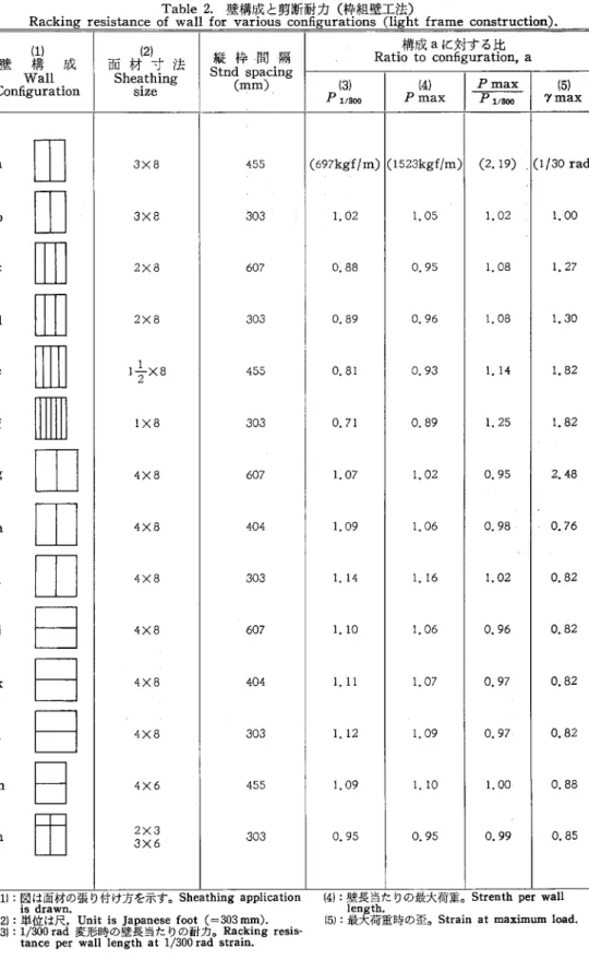
すべての構成で , Pmax は P 1/800 の 2 倍強, 'Y max は 1/300 rad の 7 倍以上となり,建築センター の内部規定に従えば , P 1/300 を許容耐力の算定ベースにすることができる。 まず面材寸法の影響であるが, a → c → E → f のように小さくなると,在来工法の場合と同様に順次耐 力が低下し, l'X8' 合板を張った f の P1/800, Pmax は, 3'X8' 合板を張った a のそれぞれ 71%. 89;;ぢ となっている。しかしながら , P maxl P 1/800 の値は f の方が 25%大きく, 'Y max も A の 2.5 倍を示し ている。 縦張りについて北米の寸今法 4'X8' と日本の寸法 3'X8' とを比べると, 北米の標準的仕様(縦枠間隔 406mm) は日本の標準的仕様 a (同 455mm) より P1沼田で 9%, Pmax で 6%高い。 縦枠間隔を 607mm とした g でも a より P 11800 で 7%, Pmax で 2%高い値を示している。 4'X8' の横張りでは 3'X8' の縦張りより耐力はさらに大きくなり , P 11800 で 10% (縦枠間隔 607mm) ~l2;;ぢ(向 303mm),
P
max で 6~9% (同じ間隔に対して〕の増加となっている。 つぎに, 3'X6' 合板を切り使いした n は,標準的仕様 a より耐力が低く,その差は P 1/旬。,P
nlax と も 5%である。 最後に縦枠本数(縦枠間隔〉の影響であるが, 同じ面材寸法でも a→b, c• d, g• h• i , i→k→l のよ うに中通りの本数が増えるにしたがって , P11曲。, Pmax,
'Y max は上昇する。 しかしながら, その割 合は縦枠 1 本の増加に対して 1~3% とわずかである。-178 ー 林業試験場研究報告第 340 号 Tabl巴1. 壁構成と努断耐力(在来工法)
Racking resistance of wall fordi妊erent con五gurations (conventional construction).
壁 (構1) 成
面材(2)寸法
縦枠間隔 Ratio tio構t成oA IE五対且する比
o configuration AWall Sheathing Stnd (msmpa)cing (3) (4)
lpmaxl 倒
con五guration slze P 118田 Pmax P 11800 I '>'max A山
3X9 455 (513kgf/m) B山
2X9 607 0.86 C山
I-!-X9 2 455 0.77 D四
1X9 303 0.65 E田
3X3, 3X6 455 0.99 F日
3X6 455 1.02 G日
3X6 455 1.06 H固
3X3 455 0.96 (1):図は面材の張り付け方を示す。 Sheathingapplication is drawn. (2):単位は尺. Unit is Japanese foot (=303mm). (1004kgf/m) (1. 96) 0.94 1.09 0.92 1.19 0.87 1.34 1.04 1.05 1.05 1. 03 1.10 1. 04 1.09 1.19 (31 : 1;300rad 変形時の壁長当たりの耐力. Racking resistance per wall length at 1/300 rad strain. (4い壁長当たりの最大耐力. Strength per wall length. (5い最大荷重時の歪. Strain at maximum load. 5. 結論 (1/31 rad) 1.41 1.72 2.59 1.03 1.03 1.06 1.31 単純化した壁モデノレ,実際的な在来工法および枠組壁工法の合板張り耐力壁について,解析的手法 lとよ り,面材の寸法や張り方が男断性能 fC及ぼす影響を調べた。その結果をまとめると次のようになる。 まず壁モテソレを対象にした計算から,つぎのととがわかった。 1) 一般的な傾向として,面材が大きいほど , P 1/800(1/300rad 変形時の壁長さ 1m 当たりの耐力),Pmax (壁長さ 1m 当たりの最大耐力)は大きくなるが, P maxl P 11800 の値や, ,>,max (最大耐カ時 の男断歪)は逆に減少する。
面材張耐力壁の構成と勇断耐力(神谷) -179 ー
Table 2. 壁構成と男断耐力(枠組壁工法〉
Racking resistance of wall for various configurations (light frame construction)
(1)
面材(2)寸法
構成 a Iζ五対gすurるa 比壁 構 成 縦枠間隔 Ratio to configuration, a
Wall Sheathing Stnd spacing
Configura tion slze (mm) (3) (4)
|pmaxl
侶)
PlI蜘 Pmax P1/8凹 'Y max
a
目
3X8 455 (697kgf/m) (1523kgf/m) (2.19) (1/30 rad) b田
3X8 303 1.02 1.05 1.02 1.00 c凹
2X8 607 0.88 0.95 1.08 1.27 d田
2X8 303 0.89 0.96 1.08 1.30 e目
l-J,_2 X8 455 0.81 0.93 1.14 1.82 f皿
lX8 303 0.71 0.89 1.25 1.82 g旧
4X8 607 1.07 1.02 0.95 2.48 h山
4X8 404 1. 09 1.06 0.98 0.76 1E
4X8 303 1. 14 1.16 1.02 0.82 1日
4X8 607 1.10 1.06 0.96 0.82 k日
4X8 404 1. 11 1.07 0.97 0.82日
4X8 303 1.12 1.09 0.97 0.82 宜1日
4X6 455 L09 1.10 1.00 0.88 n田
2X3 303 0.95 0.95 0.99 0.85 3X6 (11:図は函材の張り付け方を示す。 Sheathingapplication (4):壁長当たりの最大荷重。 Strenth per wall is drawn. length. (2):単位は尺. Unit is ]apanese foot (=303 mm). (5):最大荷重時の歪。 Strainat maximum load. 131:1βOOrad 変形時の壁長当たりの耐力。 Rackingresis -tance per wall length at 1/300 rad strain.-180-面材の寸法と縦枠問隔 Dimensions of sheathing and stud's spacing(1'= 303mm) 3'x8' @1.5' 林業試験場研究報告第 340 号 2'x8' a 0 c 2'x8' @1 ~一一ι~ d 4'x8' 喧 2' 4'x8' @1 .33' ..._,ー」ー--ι~
一
g h4'x8' 二二二三I一 面材張耐力壁の構成と努断耐力(神谷) @ l' 4'x8' が 2' -・・・.‘ ・.目・ ・....• 4'x8' 4'x6' 昨1 ・...
•••.
,_'I @1.5' [email protected]' ・. 4'x8' = 3'x6' 3'x2' Fig.9. 計算した枠組壁工法耐力壁の構成 Configrations of walIs whose racking resistances were calcu!ated (Iight frame construction). 釘間隔は面材の外周で 100mm. 中通りで 200mm. 嘩 l' @1.5' Nail spacing is 100 mm O. C. at perimeter and 200 mm O. C. at intermediate. 争..-181-第 340 号 林業試験場研究報告 18001 160 。凶凶叫∞∞ nu マ ηJLnunO ハ h 》凋斗 ZH回 co-zmw 量』@丘百四 WO 一』帽 ω 孟的 (E\ 半切る RE 塩叡 P4 調 EH 蝋制 -182 ー 5 4 勢断歪(1 0-'rad) Shear strain Fig. 10. 枠組壁工法耐力壁の荷重一男断歪曲線 Shear load -strain curves of wal1s
(light frame construction). 3 2 0 1/300 (すなわち,釘の抵抗力が大きくなる〉ととによっている。 実際の耐力壁を対象にした計算でも,モデノレの場合と同様な傾向を示している。各構成の耐力壁につい てまとめると,以下のようになる。 3'X9' の代りにその 1/3 の l' 小さな面材を張った場合, P 1/800 は低下する。 3'X8'(1' =303mm), 3) 枠組壁工法で 65% となる。 Pmax 在来工法で 71%, X8', 1'X9';を 3 枚張った耐力壁の Pmax は, P max/ P 1/800 の値は上昇する。上の例の場 も低下するが,その割合はほ PlI蜘ほどではないので, 合,との比の上昇ば在来工法で 34% ,枠組壁工法で 25%である。'Y max は面材が小さくなるほど大き くなる。上の例の場合,在来工法で 159% ,枠組壁工法で 1485ぢの上昇である。以上の結果から , P 1/蜘 の低下 lζ 相当する低減係数を寸法調整係数として壁倍率に乗じてやれば,小さな面材を張った援を耐力 と考えられる。 壁として用いる乙とに構造安全上の問題はない, P 1/800 の上昇, すなわち, 3) とは逆の現象が生じる。 4'X8' などの大きな面材を張った場合, 4) その程度は縦枠間隔によって異なる 'Y max の減少などである。 P 1/曲。ほどではない Pmax の上昇, 'Y max では約 18% が,同じ程度の縦枠間隔の耐力壁で比べた場合 , P 1/300, P max で数%と小さく, とやや大きい。 差はわずかである。 7max も 横張りは縦張りよりやや高い P1/300, P max を示す傾向にあるが, 同様である。 5)
Pmax
, 7max 面材の中通りの柱の本数が増えるとき,その柱!c打たれた釘の貢献により , P 1/800,
などは上昇するが,その度合は柱 1 本につき 1~3% とわずかである。 6)面材張耐力壁の構成と男断耐力(神谷) -183 ー 参考文献 1) 鈴木秀三・西森進: r枠組壁工法耐力壁のせん断性状に及ぼす面材の配置方法の影響について J ,日本 建築学会大会学術講演梗概集, 1283~1284, (1985) 2) 神谷文夫: r面材を釘打ちした耐力壁のせん断剛性および強度に関する理論的研究J , 日本建築学会論 文報告集, 309, 86~94, (1981)
3) International Conference of Bui1ding 0伍cials: Uniform Bui1ding Code, CA, USA, pp 780, (1982)
-184 ー 林業試験場研究報告第 340 号
Configuration of Wood Sheathed Wa11 and Its Raeking Resistanee.
Fumio KAMIYAω
Summary
Introduction
The allowa ble shear of shea th巴d wood walls is defined
,
in Japan,
by the notification of the Ministry of Construction. The notification, however, do巴s not refer to the size and the application method of sheathings in detai1. The objective of this study is to investigate the effect of the wall configuration on the shear performance.Analytical methods for predicting the shear behavior of sheathed wal1s from the maュ terial and the nai1ed joint data have been presented by several researchers. One of such methods developed by the writer (2) was used to calculate the load-deflection curves of walls. The out1ine of the theory was describcd in the text written in Japanese. However,
the explanation was omitted in this summary.
Effect of the Size of Sheathing on the Wall
Re
sistanceFirst of all, the basic relationship between the size of sheathing and the shear perforュ mance of wall was investigated. A simplified model of the wall covered with a single sheet of plywood was chosen as the subject. This model has no intermediate stud
,
thus only the perimeter of the plywood is nai1ed to the frame. The material information of the wall is as follows: Plywood thickness 9 mm(O. 35 in.) modulus of rigidity 4000 kgf {cm2(57000 psi) Nai1 slze CN 50(6 d in USA) spacmg 100mm(4in.) load-slip curve shown in Fig. 3The load-slip curve used is actual test data of the joint between Lauan plywood and western hemlock stud.
Walls with square sheathing : Fig. 4 shows how the wall resistance changes when the four sides of the plywood sheathing are changed keeping its shape square. The shear resistance of wall when the shear deformation is 1{300 rad is one of the basis of the allowable shear in Japan. Fig. 4 shows that this resistance per wall length, P 1/300, increases as the sheaュ
thing becomes largewhi1巴 the maximum load per wal1 length, P max, is almost constant regardless of the sheathing size, which results in the decreasing of the ratio ofP max to P l/蜘 (safety factor) as the sheathing becomes large.
The reason of this phenomena can be easi1y explained by the theory. See Eq.(5) which presents the realationship between the shear straincaus巴d by the nai1 slip and the slip
Received ]une 18, 1986 (1) Wood Utilization, Divison
面材張耐力壁の構成と努断耐力(神谷〉
-185-components at the corner of wal1, Se,x and Se噌・ This equation indicates that the nail slip
thus nail force, under the codition of a constant shear strain, increases as the sides of the sheathing, H e and L..increase. The relationship between the slip of the corner nai11 and the size of sheathing is also shown in Fig. 4.
The shear deformation at the maximum load
,
"
/
'
max,
decreases as thesh巴athingbecomes large. This is due to the same reason described above.WaU目 withrectangular sheathing: Fig. 5 shows how the wall r巴sistancechanges when the lengths of the plywood sheathing are changed keeping the height constant. Except forP max
,
a similar tendency to the case ofsquar巴 sheathing can b巴 seen. The maximum load per wal1length, P max, increases as the length of sheathing increases, while P max is almost constant regardless of the size in the case of square sheathing. However, since the rate of incr回se of P max is smaller than that of P 11800, the ratio ofP max toP 11蜘 decreases as the length of shea thing increases.Comparison of Wall
Re
sistanee for Various Configuration自Secondly, wall resistances for variouscon五grations of the light-frame construction and of the Japanese conventional construction were calculated, and thedi妊erencesbetween them were investigated.
The material properties of wall were same as that described in the foregoing paragraph. In the analysis of wall resistance, the 巴妊ective sizes of sheathing which are the distances between corner nails (see Fig. 1) were used. However
,
in the expression of the resistance per wal1length the wall resistance was divided by the actual length of covering according to the current method. Therefore,
notice that the resistance per wall length of the wall with a short covering is expressed smaller than that with a long covering even if their resistances per e妊ective length are the same.Fig. 6 shows the calculating method of a wall with di妊erent sizes of coverings. The overall stiffness and strength of the wal1sheathed with more than two coverings was deter司 mined by addin耳 the deformation or the resistance of each part with a single sheet. The calculation method for the wall with two coverings applied up and down depends on the bending sti旺ness of stud. In the case of Japanese conventional construction, the resistances of each part corresponding to the same strain were added because the bending sti妊ness of the column (stud) is large enough to ignore it's bending deformation. In the case of lightュ frame costruction, the strains of each part for same load were combined. The interaction of the corners of sheathing which happens wh巴n more than three corners gather at one place was ignored in the calculation.
WaUs of the Japanese conventionalcostruc低価:The calculated results for variouscon五 gurations shown in Fig. 7 are shown in Fig. 8 and Table 1.
ltcan be seen in the f gure and the table that P max and P 11蜘 decrease as the sheaュ thing becomes short in the order of A, B. C and 0_ The ratio of P 11800of 0 to that of A is
sixty-fvepercent.Th巴 similar ratio of P max is eighty-seven percent.
The shear strain at the maximum load. '"/ max, increases as the sheathing becomes short. The ratio of '"/ max of 0 to that of A is 2. 6.
The horizontal application of sheathing, G, produces slightly higher resistance than the vertical application, A. Eq. (4) indicates that the contribution of the nail located far from
-186- 林業試験場研究報告第 340 号
the center of sheathing is high. The di任erence in the resistance between the vertical appliュ cation and the horizontal application is due to thedi任erence of the contribution of the nails which fasten the covering to the intermediate studs.
The tendency mentioned above agrees weI1with the test results of SUZUKI and NISHIMORI (1).
Besides G, the application methods of E and F are commonly seen inthe 五eld when 3' x6' coverings are used. These application methods produce an equivalent or slightly higher resistance than the vertical application of 3'X9' coverings, A. The waI1sheathed with 3'x 3' coverings has lower resistanc than A. However, the difference is smal1.
Wall of the light frame constrllction: Fig. 9 shows the waI1co五gurations of w hichsti妊ness and strength are calculated. The calculated load-strain curves are shown in Fig. 10, the values ofP 113∞, P max and "1max in Table 2.
In the waI1of the light frame construction, a similar tendency to the case of the Japaュ nese conventional construction can be seen, i. e., the increases of P 11300and P max, and the decrease of"1max as the edge of covering becomes short. For example, P 1'800and
Pmax of a waI1 with I'X8' sheathing, f, are lower than those of waI1, a, by twenty-nine and eleven percent respectively. The size of sheathing materials in Canada and USA is 4'X 8ぺ A waI1 with such a size of sheathing shows a higher resistance than a waI1 with 3'X8' coverings. For instane, the typical waI1con凸guration in North America, m, is higher in P1I3帥 and Pmax by, respectively, 9 percent and 6 percent than the typicalcon五guration in }apan, a.
The resistance of the wall with horizontally placedど X8' sheet is more than the walls described above. The horizontal application of 4'x8' sheathing produces, according to the stud's spacing, a higher P 1/300 by nine to twelve percent and a higher Pmax by six to nine percent than the vertical application of 3'x 8' sheet, a.
As the stud's spacing decreases, i. e., studs which go through intermediate of covering increase, the values ofP 11800, P max and "1max increase. This is due toth巴 contribution of the nails driven into these intermediate studs. However, the contribution of the naiI on the wall resistance depends on how far the naiI exsists from th巴 sheathing's center (see Eq. (4)). And the nails driven into intermediate studs are not so far from the sheathing's center as the nails w hich fasten theperimet巴rof the sheathing. Therefore, the rates of increase ofP1I300, Pmax and "Imax are smaI1, i. e., one to three percent per one intermediate stud.