Proposal of Bi-based Textured Ceramics by High
Magnetic-field Electrophoretic Deposition Method for
High Performance Piezoelectric Energy Harvesting
A doctoral thesis
Present by
Minsu Kim
A Dissertation submitted to the University of Yamanashi in Partial
Fulfillment of the Requirements for the
Degree of Doctor of Philosophy
Special Doctoral Program for Green Energy
Conversion Science and Technology
Interdisciplinary Graduate School of Medicine and Engineering
University of Yamanashi
September 2018
I
ABSTRACT
The piezoelectric energy harvesting devices have been attracting attention because of their varying range of applications. Among these applications, battery-less devices is being highlighted and studied for their use in environmental and bio-technological fields. Such battery-less devices can be designed using piezoelectric effects. However, lead-based piezoelectric materials are widely used in applications nowadays which are harmful for environment as well as human’s health. Therefore, lead-free piezoelectric materials are being widely studied to replace lead-based piezoelectric materials.
Mainly due to these reasons, studies of lead-free piezoelectric materials have increased considerably, but they still have low piezoelectric performance. Therefore, a new breakthrough is required for increasing piezoelectric performance of lead-free piezoelectric materials. For example, 85(Bi0.5Na0.5)TiO3-15BaTiO3 (85BNT-15BT) ceramic is
representative lead-free piezoelectric material. However, their piezoelectric constant (d33) is
low, reported about 110 pC/N. Therefore, to increase piezoelectric performance, application of engineered domain configuration in lead-free piezoelectric ceramics has been studied. To apply engineered domain configuration, textured and fine-grained structure is required. Specifically in 85BNT-15BT ceramic, to apply engineered domain configuration, [111]-orientation is required. However, it is difficult to fabricate [111]-textured and fine-grained 85BNT-15BT ceramic. On the other hand, fabrication of [111]-textured BaTiO3
(BT) ceramic was reported using high magnetic field electrophoretic deposition (HM-EPD) method. Therefore, to fabricate [111]-textured and fine-grained 85BNT-15BT ceramic, HM-EPD method was investigated in this study.
However, there is no report on fabrication of 85BNT-15BT ceramic with HM-EPD method. Therefore, first, I investigated EPD method for fabrication of 85BNT-15BT green body. To
II
obtain thick and dense green body, it is required to decrease Na+ ion dissolution using solvent with low dielectric constant. Also, PEI contents should be optimized depending on particle size which was possible by changing ball-milling time. In optimum fabrication condition, suspension was ball-milled with 3 mm zirconia ball for 20 h and 0.2 g of PEI (polyethyleneimine, surfactant) with 2-propanol solvent. With this condition, thick and dense 85BNT-15BT green body was fabricated with 2.25 g of deposition weight and 54.1% of relative density.
Fabricated 85BNT-15BT green body with EPD method was sintered to confirm that it did not have any compositional deviation. In EPD processed 85BNT-15BT ceramic, it showed fine-grained structure (~ 2 μm). XRD pattern showed tetragonal Perovskite structure without secondary phases which is in good agreement with phase diagram. It was confirmed that EPD processed 85BNT-15BT ceramic had a Curie temperature of 250 oC from temperature dependent dielectric constant and XRD patterns. The value of piezoelectric constant was about 70 pC/N in EPD processed ceramic. It was similar to the value obtained from conventionally fabricated 85BNT-15BT ceramic with same processing techniques, which means 85BNT-15BT ceramic was successfully fabricated with EPD method without compositional deviation.
From the above results, I confirmed that randomly orientated 85BNT-15BT ceramic can be fabricated using EPD method. In order to fabricate textured ceramic, 85BNT-15BT green body with (001)-orientated hexagonal BT particles was fabricated using HM-EPD method at 12 T of magnetic field. To obtain highly orientated green body, hexagonal BT particle should have optimum particle size and well dispersion. In optimum fabrication condition, large hexagonal BT (~ 4 μm) suspension was ball-milled with 10 mm zirconia ball for 72 h and 0.5 g of PEI (polyethyleneimine, surfactant) with 2-propanol solvent. BNT powder was added
III
after ball-milling procedure to prevent generation of small aggregate in hexagonal BT particles. With this condition, thick and dense 85BNT-15BT green body was obtained with deposition weight of 2.41 g and 55.8% relative density with high orientation factor in both sides of surface as 83.3% (bottom) and 88.4 % (top).
After that, 85BNT-15BT green body with (001)-orientated hexagonal BT particles was sintered in order to fabricate [111]-textured and fine-grained 85BNT-15BT ceramic. From the results, it was confirmed that HM-EPD processed 85BNT-15BT ceramic was dense, fine-grained without any compositional deviation. However, HM-EPD processed ceramic did not show any orientation. This result can be explained because (001)-orientated hexagonal BT particle is disappeared during sintering procedure. Because of this reaction behavior, I conclude that [111]-textured and fine-grained 85BNT-15BT ceramic could not be fabricated using green body with HM-EPD method. Therefore, as a future work, I suggest preparation of BNT-BT core-shell particle with solvothermal method. I hope that BNT-BT core-shell particle is grown by maintaining orientation during sintering procedure which can lead to fabrication of [111]-textured and fine-grained 85BNT-15BT ceramic. I hope that it will show superior piezoelectric properties due to application of engineered domain configuration.
IV
LIST OF CONTENTS
ABSTRACT ... I
LIST OF CONTENTS ... IV
LIST OF FIGURES ... VI
Chapter 1 Introduction and Background ... 1
1.1 Introduction ... 1
1.2 Background ... 3
1.2.1 Piezoelectric energy harvesting ... 4
1.3 Piezoelectric materials ... 4
1.3.1 Lead-based piezoelectric materials ... 5
1.3.2 Lead-free piezoelectric materials ... 6
1.4 Engineered domain configuration ... 8
1.4.1 Morphotropic phase boundary (MPB) ... 8
1.4.2 Engineered domain configuration ... 10
1.4.3 Engineered domain configuration in lead-free piezoelectric ceramics ... 12
1.5 Strategy of high performance lead-free piezoelectric ceramic... 13
1.5.1 Material design for application of engineered domain configuration ... 13
1.5.2 Texture method ... 15
1.5.3 High magnetic field electrophoretic deposition (HM-EPD) method ... 16
1.6 Outline of the thesis ... 18
Chapter 2 Fabrication of thick and dense 85BNT-15BT green body with
EPD method ... 20
2.1 Introduction ... 20
2.2 Experimental details ... 22
2.3 Results and discussion ... 24
2.3.1 Fabrication of BNT green body with EPD method ... 24
2.3.2 Fabrication of 85BNT-15BT green body with EPD method ... 32
V
Chapter 3 Electrical properties of 85BNT-15BT ceramic fabricated by EPD
method ... 42
3.1 Introduction ... 42
3.2 Experimental details ... 43
3.3 Results and discussion ... 46
3.4 Conclusion... 52
Chapter 4 Fabrication of 85BNT-15BT green body with (001)-orientated
hexagonal BT particles using HM-EPD method ... 54
4.1 Introduction ... 54
4.2 Experimental details ... 56
4.3 Results and discussion ... 58
4.4 Conclusion... 67
Chapter 5 Fabrication of [111]-textured 85BNT-15BT ceramic from green
body with (001)-orientated hexagonal BT particles ... 69
5.1 Introduction ... 69
5.2 Experimental details ... 70
5.3 Results and discussion ... 71
5.4 Conclusion... 76
Chapter 6 Conclusion ... 81
Reference ... 87
List of research achievement ... 91
VI
LIST OF FIGURES
Chapter 1
Figure 1. 1 Applications of piezoelectric materials with natural energy sources1... 1 Figure 1. 2 Lead-based piezoelectric materials with piezoelectric constant (d33) ... 5
Figure 1. 3 The phase diagram of Pb(Zr1-xTix)O3 ceramic24 ... 6
Figure 1. 4 The piezoelectric constant (d33), dielectric constant (ε) and
electromechanical coupling factor (kp) in PZT ceramic with MPB24 ... 8
Figure 1. 5 Spontaneous polarization produced by (a) non-centrosymmetric structure in Perovskite structure, (b) distorted structure (Flexoelectricity)35 ... 9 Figure 1. 6 Schematic diagram of Structure-Gradient Region (SGR) in MPB region of PZT ceramic. ... 9 Figure 1. 7 Domain structure in PZN-PT single crystal under electric field. (a) (111)
orientation. (b) (001) orientation7,8 ... 10 Figure 1. 8 Schematic diagram of domain wall in piezoelectric material. ... 11 Figure 1. 9 Domain structure in [111]-orientated BT single crystal38 ... 12 Figure 1. 10 Domain structure and size dependent of grain size in BT ceramics40. 13 Figure 1. 11 Phase diagram of BNT-BT system. Red line indicate 85BNT-15BT
composition21 ... 14 Figure 1. 12 Equivalent domain depend on crystal direction of engineered domain
configuration in tetragonal structure. ... 14 Figure 1. 13 Mimetic diagram of template grain growth (TGG) method.41 ... 15 Figure 1. 14 Mechanism of HM-EPD method. (a) Accumulation of particles on
electrode due to surface charge. (EPD) (b) Particle orientation under magnetic field due to magnetic anisotropy. (c) Accumulation of orientated particles on electrode (HM-EPD). ... 16 Figure 1. 15 XRD patters of hexagonal BaTiO3 green bodies and sintered ceramic
fabricated by HM-EPD (12 T) and EPD (0 T) method. (a) Green bodies and mixture powder. (b) Sintered ceramics and crushed powder.19 ... 17 Figure 1. 16 Strategy of fabrication of [111]-textured and fine-grained
VII
Chapter 2
Figure 2. 1 Application of electrophoretic deposition for automobile coating49 ... 20 Figure 2. 2 Particle accumulation during EPD method. (a) insulator particles, (b) PEI
adsorbed particles... 21 Figure 2. 3 Schematic diagram of electrophoretic deposition (EPD) instrument ... 23 Figure 2. 4 BNT and BT green bodies fabricated by EPD method. (a) Morphologies and properties (Number indicates deposition weights / relative green densities). (b) The deposition time dependent electric current during EPD method (Inset figure is magnification of BT result). ... 25 Figure 2. 5 EPD method in sodium beta-alumina showing dependence of specific
conductance of various solvents with their dielectric constants.51 ... 26 Figure 2. 6 BNT green bodies fabricated by EPD method with ethanol, acetone and 2-propanol solvent. (a) Table of dielectric constants of different solvents at 25
o
C with the respective electric currents. (b) Morphologies and deposition weights. (c) The deposition time dependent electric current during EPD method. ... 27 Figure 2. 7 SEM image of particle and size distribution (a) hexagonal BT, (b) BNT
powders ... 28 Figure 2. 8 The deposition time dependent electric current during EPD method for
fabrication of BNT green bodies with once ball-milling. Inset figure shows morphology and properties (Number indicates deposition weights / relative green densities). ... 28 Figure 2. 9 BNT green bodies fabricated by EPD method with 25~75 V/cm of
electric field (a) Morphologies and properties (Number indicates deposition weights / relative green densities). (b) The deposition time dependent electric current during EPD method. ... 29 Figure 2. 10 Deposition weight was plotted with deposition time in BNT green
bodies fabricated with 75 V/cm of electric field for 10~60 min. ... 31 Figure 2. 11 The deposition time dependent electric current during EPD method in
85BNT-15BT green body fabricated with 75 V/cm of electric field and 20 h ball-milling time (PEI : 0.2 g). The inset figure shows morphology and
properties (Number indicates deposition weight / relative green density). ... 32 Figure 2. 12 SEM images of 85BNT-15BT green bodies fabricated by EPD method
using suspensions with ball milling time for 2~30 h. Yellow arrows indicate remaining large particles. ... 33 Figure 2. 13 Green bodies fabricated by EPD method using various suspensions with
ball milling time for 2~30 hours. (PEI : 0.2 g) (a) Morphologies and properties (Number indicates deposition weights / relative green densities). (b) The
VIII
deposition time dependent electric current during EPD method. (c) The
deposition weight and relative green density dependent ball milling time. .... 35 Figure 2. 14 Green bodies fabricated by EPD method with various PEI
concentrations. (a) Morphologies and properties (Numbers indicate deposition weight / relative green density). (b) The deposition time dependent electrical current during EPD method. ... 37 Figure 2. 15 Green bodies fabricated by EPD method with ball milling time for 20
hours and 3 hours under 0.3 g of PEI contents. EPD method was conducted twice; 1st run and 2nd run. (a) Morphologies and properties (Numbers indicate deposition weight / relative green density). (b) The deposition time dependent electrical current during EPD method. ... 38 Figure 2. 16 Schematic representation of PEI attached model with various condition
(a) Low PEI concentration. (b) High PEI concentration and short ball milling time. (c) High PEI concentration and long ball milling time ... 39
Chapter 3
Figure 3. 1 Curie temperature (TC), piezoelectric constant (d33) and dielectric
constant (εr) in BNT-BT based ceramic. Black circles indicate 85BNT-15BT23
... 42 Figure 3. 2 XRD patterns of green bodies fabricated by EPD method (Blue line).
85BNT-15BT, hexagonal BT and BNT powder were used as reference. ... 44 Figure 3. 3 SEM images of 85BNT-15BT ceramics fabricated by conventional
method sintered at (a) 1100 oC, (b) 1125 oC, (c) 1150 oC (yellow arrow indicates abnormal grain growth). ... 45 Figure 3. 4 Surface morphologies of as sintered 85BNT-15BT ceramics fabricated by
(a) Conventional and (b) EPD method magnification with x 10,000. ... 46 Figure 3. 5 SR-XRD patterns of 85BNT-15BT ceramics fabricated by conventional
and EPD methods with diffraction angles in range of (a) 5~20o, (b) 9.5~11o, [110] peaks (c) 12.4~12.6o, [111] peak (Note: wavelength value in the experimental procedure is 0.494231(1) Å)... 47 Figure 3. 6 2D contour plots of XRD patterns of [200] peaks in 85BNT-15BT
ceramics fabricated by (a) Conventional and (b) EPD method in temperature range of 300 to 600 K... 48 Figure 3. 7 Temperature dependence of dielectric constants (ɛ ́) and dielectric losses
(tanδ) of 85BNT-15BT ceramics fabricated by (a) Conventional and (b) EPD method at various frequencies. ... 49 Figure 3. 8 Ferroelectric and reverse piezoelectric properties of 85BNT-15BT
IX
field of 60 kV/cm (a) Ferroelectric P-E hysteresis loops. (b) Bipolar S-E curves. (c) Unipolar S-E curves. ... 50 Figure 3. 9 Bar graph of piezoelectric constant of 85BNT-15BT ceramics prepared
by conventional and EPD method ... 51
Chapter 4
Figure 4. 1 Particle size distribution of hexagonal BT powder. (a) Initial hexagonal BT, (b) Large hexagonal BT, (c) Fine hexagonal BT ... 56 Figure 4. 2 Introduction of HM-EPD instrumentation. ... 57 Figure 4. 3 XRD patterns of 85BNT-15fineBT green bodies fabricated with 3 mm
zirconia ball-milling for 20 h (PEI : 0.2 g). Inset figure shows morphology and properties (Number indicates deposition weight / relative green density). ... 59 Figure 4. 4 XRD patterns of 85BNT-15fineBT green bodies fabricated with 3 mm zirconia ball-milling for 72 h (PEI : 0.5 g). Inset figure shows morphologies and properties (Number indicates deposition weight / relative green density). ... 60 Figure 4. 5 Optimum hexagonal BT particle size for achieving orientated and
dispersed hexagonal BT particles in suspension... 61 Figure 4. 6 Ball-milling conditions for achieving optimum hexagonal BT particle
size and SEM image of dried powder after ball-milling. ... 61 Figure 4. 7 XRD patterns of top and bottom side of 85BNT-15largeBT green body
fabricated with 10 mm zirconia ball-milling for 72 h (PEI : 0.5 g). Inset figure shows morphology and properties (Number indicates deposition weights / relative green densities). ... 63 Figure 4. 8 Generation of small aggregate. (a) High solid concentration in suspension.
(b) Generation of small aggregate during ball-milling procedure. (c) Small aggregation with PEI adsorption... 64 Figure 4. 9 Green body fabrication with suspension included small aggregations and
well dispersed particles. (a) Suspension with small aggregates and well dispersed hexagonal BT particles. (b) Slowly deposited small aggregates. (c) Deposited green body with small aggregates and dispersed hexagonal BT particles. ... 64 Figure 4. 10 Fabrication of well dispersed hexagonal BT with ball milling method. (a)
Preparation of hexagonal BT suspension with low solid concentration, (b) Well dispersed hexagonal BT particles after ball-milling procedure, (c) Add BNT powder after ball-milling. ... 65 Figure 4. 11 XRD patterns of top and bottom side of 85BNT-15largeBT green body fabricated with 10 mm zirconia ball-milling for 72 h (PEI : 0.5 g). In this case,
X
BT powder was ball-milled and then BNT powder was added after ball-milling. Inset figure shows morphology and properties (Number indicates deposition weight / relative green densities). ... 66 Figure 4. 12 SEM images of deposited 85BNT-15BT green body (a) Top side of
15LargeBT-72h, (b) Bottom side of 15LargeBT-72h... 67
Chapter 5
Figure 5. 1 Stacking sequence of hexagonal and tetragonal BT structure. ... 69 Figure 5. 2 Schematic diagram of fabrication of [111]-textured 85BNT-15BT
ceramic using green body fabricated by HM-EPD method ... 70 Figure 5. 3 Surface morphologies of as sintered 85BNT-15BT ceramics fabricated by
(a) EPD and (b) HM-EPD method. ... 71 Figure 5. 4 XRD patterns of 85BNT-15BT ceramic sintered at 1125 oC for 2h with
green bodies fabricated by EPD (0 T) and HM-EPD (12 T) method... 72 Figure 5. 5 Temperature dependence of dielectric constant (ε’) of 85BNT-15BT
ceramics fabricated by EPD and HM-EPD method at 100 kHz. ... 73 Figure 5. 6 Model of change of particles in 85BNT-15BT green body with
(001)-orientated hexagonal BT during sintering procedure. (a) Coexistence of randomly orientated BNT particles and (001)-orientated hexagonal BT particle. (b) Diffusion with growth of BNT particles. (c) Fabrication of 85BNT-15BT particle with disappeared hexagonal BT particle. (d) Fabrication of randomly orientated 85BNT-15BT ceramic ... 73 Figure 5. 7 XRD patterns of 85BNT-15BT ceramics sintered in temperature range of
800~1000 oC for 5 h with green bodies fabricated by HM-EPD (12 T) method in range of (a) 20~60o, (b) 38~41o, (006)H hexagonal BT peak, (111)R BNT
rhombohedral peak and (111)T 85BNT-15BT tetragonal peak, (c) 46~47o,
(200)R BNT peak, (002)T and (200)T 85BNT-15BT peaks... 74
Figure 5. 8 SEM images of 85BNT-15BT ceramics sintered in temperature range of 800~1000 oC for 5 h with green bodies fabricated by HM-EPD (12 T) method. Yellow arrows indicate larger particles. (a) 800 oC for 5 h. (b) 850 oC for 5 h. (c) 900 oC for 5 h. ... 75 Figure 5. 9 Model for fabrication of (111)-textured 85BNT-15BT ceramic using
green body with (001)-orientated hexagonal BT particle. (a) Coexistence of randomly orientated BNT particles and (001)-orientated hexagonal BT particle. (b) Diffusion with growth of hexagonal BT particle. (c) Fabrication of
85BNT-15BT particle with remaining orientation direction. (d) Fabrication of (111)-textured 85BNT-15BT ceramic ... 77 Figure 5. 10Fabrication of 85BNT-15BT green body with orientated core-shell
particles. (a) Core-shell structure with hexagonal BT core and epitaxially coated BNT shell. (b) Orientated core-shell structure at high magnetic field. (c)
XI
Fabrication of 85BNT-15BT green body with orientated core-shell particles with HM-EPD method. ... 77 Figure 5. 11Reaction of green body with core-shell particles and BNT particles
during sintering procedure. (a) Coexistence of large and orientated core-shell BNT-BT particle and small BNT particle. (b) Reaction between core-shell particle and BNT particles during sintering procedure. (c) Fabrication of [111]-orientated 85BNT-15BT particle. ... 78 Figure 5. 12Fabricated LN-BKT core-shell structure using solvothermal method.
(a) STEM-EDX images of core-shell structure. (b) FE-TEM image of core-shell structure.62 ... 79
1
Chapter 1 Introduction and Background
1.1 Introduction
Figure 1. 1 Applications of piezoelectric materials with natural energy sources1
Nowadays, attention is being paid in using piezoelectric materials for energy harvesting devices converting mechanical energy such as wind, tidal wave, vibration and, human’s movement into electrical energy as shown in figure 1.1.1-5
However, piezoelectric material in energy harvesting devices has a disadvantage of low efficiency for electricity generation and limitation of device sizes. Therefore, piezoelectric energy harvesting has been developed for using micro-size generator and sensors without external power supply. For example, in figure 1.1, sensor nodes with piezoelectric material can be operated using generated electricity from natural energy such as sunlight and wind. In this case, one of the advantages is maintenance as these devices do not require change of batteries.4,5 Especially in bio-technology, piezoelectric energy harvesting devices are considered to be used in heartbeat application because it can generate electricity from
2
heartbeat vibration. Current electronic devices of bio-technology are generally supplied with electric energy from built-in battery. However, battery-type electronic devices have a discharging problem which requires additional surgery for recharging. In this respect, a piezoelectric energy harvesting device can solve this problem because it can generate electric energy itself from human’s body.5
Among the existing piezoelectric materials, Pb(Zr, Ti)O3 (PZT) based ceramics have
excellent piezoelectric properties and are most commonly used in piezoelectric devices. However, as is well known, lead is harmful for nature and human’s body and therefore, is not appropriate, especially for bio-technological applications. Moreover, since July 2006, legislations such as RoHS/WEEE (restriction of hazardous substances/waste electrical and electronic equipment) demand the elimination of toxic materials (Pb, Hg, Cd, Cr6+, PBB and PBDE) from the consumer products.6 Until then, lead-based piezoelectric materials were prevalent because of their good performance compared with available lead-free piezoelectric materials. However, after 2006, lead-free piezoelectric ceramics have been attracting attention in replacing lead-based piezoelectric materials.
In the study of piezoelectric materials, PZN-PT or PMN-PT single crystal shows the highest performance due to achievement of engineered domain configuration.7,8 Taking this into account, engineered domain configuration has been applied to increase the piezoelectric properties of lead-free piezoelectric materials. In order to achieve engineered domain configuration in lead-free piezoelectric materials, following conditions are found to be important.9,10
1. Fabrication of orientated ceramics along non-polar direction. (Texture technique)
3
Generally, template grain growth (TGG) method is widely used for fabrication of textured ceramics.11-16 However, it is difficult to satisfy above conditions from TGG method because texture condition is strongly affected by template materials. For example, it is difficult to fabricate [110] or [111]-textured ceramics by TGG method as it is difficult to control fabrication direction.16 In addition, TGG method finds difficulty in fabricating fine-grained ceramic because of large size of template particles. To avoid these problems associated with template material, high magnetic field electrophoretic deposition (HM-EPD) method have been studied.17-20 HM-EPD method has already been studied and successful results were reported in α-Al2O3,17 TiO218 and BaTiO319. In HM-EPD method, orientation direction is
easily controlled with magnetic field while textured ceramics with fine grains can be fabricated.
Among lead-free piezoelectric ceramics, 85(Bi0.5Na0.5)TiO3-15BaTiO3 (85BNT-15BT)
ceramics is under attention because BNT-BT based ceramics are representative lead-free piezoelectric materials as they possess high Curie temperature (~250 oC) and suitability for mass production.16,21-23
In this study, to achieve engineered domain configuration in lead-free piezoelectric ceramic, 85BNT-15BT green body was fabricated using HM-EPD method. During this study, optimized conditions were determined for fabrication of thick, dense and highly orientated 85BNT-15BT green body with HM-EPD method. I hope that this technique can serve as a bridge for development of piezoelectric materials with engineered domain configuration.
1.2 Background
In this section, the piezoelectric energy harvesting and current status in lead-free piezoelectric materials are reviewed. Following this, engineered domain configuration will be
4
introduced and achievement strategy will be presented.
1.2.1 Piezoelectric energy harvesting
Piezoelectricity is a physical phenomenon in which mechanical energy is converted into electrical energy and vice versa. Currently, piezoelectric devices are being widely used such as transducers, actuators, sensors and generators.1-5
In piezoelectric energy harvesting, it is well-known that piezoelectric devices are not appropriate to replace common electric generators (i.e. thermal power generator, atomic power generator) due to their low efficiency of power generation. Therefore, piezoelectric energy harvesting is focused on using small power from waste energy. As mentioned above, piezoelectric energy harvesting devices have advantage of self-electricity generation in small devices. Therefore, piezoelectric energy harvesting devices are considered to be used in environmental and bio-technological fields as they can generate electricity from natural sources. Lead-based piezoelectric materials are predominantly being used in these devices because of their high piezoelectric properties. However, they are harmful for environment and human health. Therefore, investigation of lead-free piezoelectric material is required to prevent environmental pollution as well as harm to human health. Lead-free piezoelectric materials still have low piezoelectric performance in order to be applied in real applications. Consequently, high performance lead-free piezoelectric materials are required to replace lead-based piezoelectric materials, keeping in mind, the resultant impact on the environment and human health.
1.3 Piezoelectric materials
In this section, current status of lead-based and lead-free piezoelectric materials will be introduced.
5 1.3.1 Lead-based piezoelectric materials
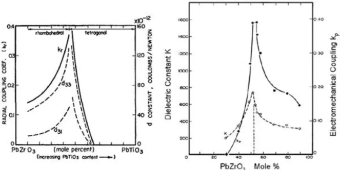
From the literature survey, various lead-based piezoelectric materials and their properties are shown in figure 1.2. It is well-known that PZT (Pb(Zr1-xTix)O3) ceramics show high
piezoelectric properties around its morphotropic phase boundary (MPB) region, which is the region of co-existence of rhombohedral and tetragonal phases. The phase diagram of PZT shows that at 52 mol% of PbZrO3 and 48 mol% of PbTiO3 lies in the MPB composition as
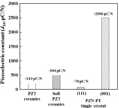
shown in figure 1.3. At this MPB composition, piezoelectric constant was reported about 210 pC/N.24 In addition, doping of aliovalent ions in PZT-based materials enhance the dielectric and piezoelectric properties. For example, substitution of higher valence ions (Nb5+) on Zr4+/Ti4+ on PZT ceramics, so called soft PZT, enhance piezoelectric constant to about 500 pC/N, because soft PZT can enhance the domain wall motion.25,26 Nowadays, soft PZT is widely used in commercial applications because it is easy to apply in mass production. Since 1990, ultrahigh piezoelectric constant was reported from Pb(Zn1/3Nb2/3)O3-PbTiO3 (PZN-PT)
single crystal. Interestingly, PZN-PT single crystal has different piezoelectric properties along
6
different orientation direction. For example, [001]-direction orientated PZN-PT single crystal shows ultra-high piezoelectric constants over 2,000 pC/N while [111]-direction orientated PZN-PT single crystal shows low piezoelectric constant of about 70 pC/N as shown in figure 1.2.7,8 This phenomenon is originated from achievement of engineered domain configuration which can be achieved when crystal is orientated along non-polar direction.8
1.3.2 Lead-free piezoelectric materials
Recently, many lead-free compositions are currently under study for environment-friendly piezoelectric devices. As a candidate of lead-free piezoelectric materials, most widely investigated systems are (Bi0.5Na0.5)TiO3 (BNT), (K0.5Na0.5)NbO3 (KNN) and BaTiO3 (BT)
and their solid solutions.
BT-based ceramics have been considered a good lead-free candidate material. However, pure BT ceramic have relatively low Curie temperature of TC ~130 oC.24 A material with
improved piezoelectric properties, Ba(Ti0.8Zr0.2)O3-(Ba0.7Ca0.3)TiO3 (BZT-BCT) has been
reported with high piezoelectric coefficient of ~620 pC/N in 2009. However the Curie temperature was approximately 93 oC. This problem of low Curie temperature in BT and its
7 solid solutions limit their practical applications.27
In KNN system, K+ and Na+ co-occupy A-site while Nb5+ occupies the B-site of the Perovskite structure. Saito et al. fabricated textured Li+, Ta5+ and Sb5+ substituted KNN ceramic which exhibited high piezoelectric coefficient of 416 pC/N as well as relatively high Curie temperature of ~250 oC. After that, KNN has been considered as one of the superior lead-free candidate materials to replace the lead-based materials.28 However, KNN based materials have a problem of hygroscopic starting materials. It is difficult to weigh K2CO3 and
Na2CO3 exactly because of their sensitivity to moisture. Moreover, KNN has a poor
sinterability due to presence of volatile K and Na elements.29-31 These problems can be solved by using specific methods such as SPS (Spark Plasma Sintering) and HP (Hot Pressing). However, these methods are difficult to be applied for mass production.30,31
BNT has an ABO3 perovskite structure with Bi3+ and Na+ existing on A-site and Ti4+
existing on B-site. Pure BNT has good advantages such as high Curie temperature (TC ~ 320 o
C) and a large remnant polarization (Pr = 38 μC/cm2). However, BNT possesses drawbacks
as well, such as a large coercive field (Ec) of ~ 7.3 kV/mm and a high conductivity, which
cause problems in the poling process.32 In order to improve the piezoelectric properties, the solid solutions of BNT-BT were synthesized. However, BNT-BT systems have depolarization temperature (Td), which is ferroelectric to anti-ferroelectric phase transition temperature. In
MPB composition of BNT-BT system, depolarization temperature is about 150 oC which encounter the same problem as in BT based system. Moreover, BNT-BT systems still have relatively low piezoelectric properties of ~140 pC/N.23,33 Despite these problems, BNT based systems have a good potentiality to be brought into real applications as they can be applied for mass production. Because of this trait, they have already been used in commercial product.22,34 In this perspective, the BNT-based system has been selected as a material of investigation.
8 1.4 Engineered domain configuration
Among lead-based piezoelectric materials, the highest piezoelectric constant was achieved in PZN-PT single crystal due to application of engineered domain configuration. In this section, I introduce engineered domain configuration and attempts of application of engineered domain configuration in lead-free piezoelectric ceramics.
1.4.1 Morphotropic phase boundary (MPB)
Generally, piezoelectric properties are increased at MPB region which is the region of co-existence of different phases. For example, in PZT ceramic, the highest piezoelectric constant (d33) and electromechanical coupling factor (kp) was obtained at MPB region as
shown in figure 1.4.24
Piezoelectric properties are originated from spontaneous polarization which depends on crystal structure. In Perovskite structure, spontaneous polarization is produced due to non-centrosymmetric structure as shown in figure 1.5(a).24 On the other hands, it is known
Figure 1. 4 The piezoelectric constant (d33), dielectric constant (ε) and electromechanical
9
that, in flexoelectricity, spontaneous polarization can be produced by distorted structure as shown in figure 1.5(b).35 In MPB region of PZT ceramic, distorted structure is observed between rhombohedral and tetragonal phases due to structure-gradient region as shown in figure 1.6.36,37 This distorted structure is considered as a reason for enhancement of the piezoelectric properties. Therefore, in PZT ceramic, higher piezoelectric properties can be obtained at MPB region as shown in figure 1.4.
Figure 1. 5 Spontaneous polarization produced by (a) non-centrosymmetric structure in
Perovskite structure, (b) distorted structure (Flexoelectricity)35
Figure 1. 6 Schematic diagram of Structure-Gradient Region (SGR) in MPB region of PZT
10 1.4.2 Engineered domain configuration
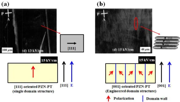
In PZN-PT single crystal, [111]-orientated PZN-PT single crystal has low piezoelectric constant of about 70 pC/N while [001]-orientated PZN-PT single crystal shows ultra-high piezoelectric constant over 2,000 pC/N. This phenomenon is occurred by achievement of engineered domain configuration as shown in figure 1.7.7,8 PZN-PT single crystal has rhombohedral Perovskite structure which has (111) polar direction. Therefore, [111]-orientated PZN-PT single crystal is fabricated as a single domain as in figure 1.7(a) because polar direction and electric field direction are same. On the other hand, [001]-orientated PZN-PT single crystal is fabricated as a multi-domain configuration as in figure 1.7(b) when electric field is applied, which is called engineered domain configuration. It is considered that domain wall plays important role in enhancement of piezoelectric properties. In engineered domain configuration, a lot of domain wall is included in domain structure. As mentioned above, distorted structure can enhance piezoelectric properties in MPB region. Domain wall also can be produced in distorted structure between 180o and 90o
Figure 1. 7 Domain structure in PZN-PT single crystal under electric field.
11
domains as shown in figure 1.8.36, 37 However, domain wall is easily disappeared by domain wall motion upon application of electric field as shown in figure 1.7(a). While, domain wall is fixed in engineered domain configuration even under electric field as shown in figure 1.7(b). Therefore, engineered domain configuration shows enhanced piezoelectric constant due to distorted structure as in MPB structure.
To achieve engineered domain configuration in lead-free piezoelectric material, [111]-orientated BaTiO3 (BT) single crystal was investigated.38 It is well-known that BT
single crystal has tetragonal Perovskite structure in room temperature. In tetragonal symmetry, the spontaneous polarization direction is along [001], thus ceramics with crystallographic orientation along [110] or [111] directions are required to achieve engineered domain configuration. However, [111]-orientated BT single crystal had low piezoelectric constant about 203 pC/N despite achievement of engineered domain configuration.38 To clarify the differences in piezoelectric performance between PZN-PT and BT single crystals, domain structure of BT single crystal was observed as shown in figure 1.9. In figure 1.9, in [111]-orientated BT single crystal, engineered domain configuration was observed when domain size was bigger as compared with PZN-PT single crystal with smaller domain size as in figure 1.7(b)7, 8 As mentioned above, domain wall is related to increased piezoelectric
12
properties. However, BT single crystal has a domain size which is too big to obtain ultra-high piezoelectric performance. In a single crystal, it is difficult to control domain size without compositional change. Therefore, it is considered difficult to apply engineered domain configuration in a single crystal of BT based material.
1.4.3 Engineered domain configuration in lead-free piezoelectric ceramics
BT ceramic is well-known piezoelectric material and piezoelectric constant was reported about 190 pC/N by Jaffe et. al.24 In 2007, Karaki et. al. reported fine-grained BT ceramic (~1 μm) having enhanced piezoelectric performance about 460 pC/N while Wada et al. reported [110]-textured BT ceramic showing enhanced piezoelectric performance about 788 pC/N.10 According to figure 1.10, domain size is proportional to grain size and domain configuration is changed with grain size.39 Hence, it is considered that fine-grained BT ceramic has high piezoelectric property because of an increase of domain wall density with decreasing grain size while [110]-textured BT ceramic has increased piezoelectric property due to achievement of engineered domain configuration with crystal orientation. Therefore, in BT ceramic, I assumed that fine-grained and textured ceramic will be expected to show much higher piezoelectric property. However, pure BT ceramic have relatively low Curie temperature of ~130 oC which finds difficulty in real application. Therefore, lead-free piezoelectric ceramics with high Curie temperature, such as BNT, KNN based materials, is required so as to apply
13
engineered domain configuration. However, there are a few reports on such application in BNT-BT based ceramics and no reports in KNN based ceramics.
1.5 Strategy of high performance lead-free piezoelectric ceramic
I noticed that the highest piezoelectric performance is achieved with engineered domain configuration. Engineered domain configuration has shown increased domain wall density which is considered to enhance piezoelectric performance tremendously. So, in this section, I introduce strategy to fabricate high-performance lead-free piezoelectric ceramic applying engineered domain configuration.
1.5.1 Material design for application of engineered domain configuration
To apply engineered domain configuration in lead-free piezoelectric ceramics, a single phase structure is required and orientation should be along non-polar direction. Among the lead-free piezoelectric ceramics, BNT-BT based ceramics are suitable because it has already been commercialized as proto-type of lead-free piezoelectric materials.22,34 According to the phase diagram of BNT-BT system reported by Takenaka et al. shown in figure 1.11, BNT-BT
14
with 15 mol% of BT composition (85BNT-15BT) has tetragonal symmetry as indicated by red line which is same to BT ceramic. Moreover, it has no depolarization temperature (Td)
and possesses higher Curie temperature.16,21
In figure 1.12, equivalent domain direction is shown in tetragonal Perovskite structure under electric field. [001] direction is polar direction and it makes single domain structure when electric field is applied. On the other hand, [110] or [111] directions have 2 or 3 equivalent domains under electric field which is known as engineered domain configuration. Therefore, I expect that [111]-textured 85BNT-15BT ceramic have higher piezoelectric
Figure 1. 11 Phase diagram of BNT-BT system. Red line indicate 85BNT-15BT
composition21
Figure 1. 12 Equivalent domain depend on crystal direction of engineered domain
15
properties than [110]-textured ceramic because it has high domain wall density due to larger number of equivalent domains. Moreover, fine-grained 85BNT-15BT ceramic is expected to have enhanced piezoelectric properties due to high domain wall density. However, there are a few reports of the fabrication of textured 85BNT-15BT ceramic because it is not an MPB composition, which is 7~8 mol% BT.16 Especially, there is no report of [111]-textured and fine-grained 85BNT-15BT ceramic. Therefore, in this study, I have investigated to fabricate [111]-textured and fine-grained 85BNT-15BT ceramic. [111]-textured and fine-grained 85BNT-15BT ceramic with engineered domain configuration is expected to exhibit superior piezoelectric properties due to application of engineered domain configuration.
1.5.2 Texture method
Generally, to fabricate textured ceramic, template grain growth (TGG) method is widely used as shown in figure 1.13.11-16, 41 Unfortunately, it is difficult to fabricate [111]-textured 85BNT-15BT ceramic with TGG method because texture condition is strongly affected by template materials.11-16It is favorable to have specific shapes such as needle-like or plate-like template for TGG method while BNT and BT particles showed spherical shape which is difficult to be applied in TGG method. Moreover, TGG method is difficult to fabricate [110] or [111]-textured ceramics as it is difficult to control fabrication direction.16In addition, TGG method finds difficulty in fabricating fine-grained ceramic because of large size of template particles as shown in figure 1.13. Therefore, to avoid problems associated with template
16
material, I have studied HM-EPD method for fabrication of [111]-textured and fine-grained 85BNT-15BT ceramic.
1.5.3 High magnetic field electrophoretic deposition (HM-EPD) method
To obtain textured and fine-grained ceramic, fabrication of green body with HM-EPD method was studied as shown in figure 1.14.17-20 If particles in suspension have surface charge as shown in figure 1.14(a), they accumulate on electrode when electric field is applied. This procedure is called electrophoretic deposition (EPD) method. In addition, if particle has magnetic anisotropy, it is orientated when magnetic field is applied as shown in figure 1.14(b).20 Finally, green body with orientated particles can be obtained using HM-EPD method as shown in figure 1.14(c).
In previous study, our group reported that [111]-textured BT ceramic was fabricated by HM-EPD method.19 It is known that, in diamagnetic material, magnetic anisotropy is related to c/a ratio. In this case, high c/a ratio is important for magnetic alignment.20 Therefore, hexagonal BT particle was used to achieve magnetic alignment because of its high c/a ratio ~ 2.44. Figure 1.15(a) shows XRD patterns of green bodies fabricated by HM-EPD and EPD method (12 T and 0 T respectively). According to XRD patterns, (001)-orientated hexagonal
Figure 1. 14 Mechanism of HM-EPD method. (a) Accumulation of particles on electrode due
to surface charge. (EPD) (b) Particle orientation under magnetic field due to magnetic anisotropy. (c) Accumulation of orientated particles on electrode (HM-EPD).
17
BT green body was obtained at 12 T due to increased intensity of (006) peak while there was no orientation at 0 T which showed similar XRD patterns to that of powder. After sintering at 1350 oC, green body with (001)-orientated hexagonal BT particles was converted to [111]-textured tetragonal BT ceramic as shown in figure 1.15(b). This transformation is occurred due to similar stacking sequence between (001) direction hexagonal and (111) direction tetragonal Perovskite symmetry.42 However, in this case, because of high phase transition temperature (~ 1350 oC) between hexagonal to cubic structure, sintered BT ceramic had large grain size of about 50 μm, due to which low piezoelectric properties were reported.19 Moreover, BT ceramic has a problem of low Curie temperature. On the other hand, 85BNT-15BT ceramic has advantages of high Curie temperature and lower sintering temperature compared with hexagonal BT case. Therefore, in this thesis, I investigated that it is possible to fabricate 85BNT-15BT green body with (001)-orientated hexagonal BT particle using HM-EPD method to fabricate [111]-textured and fine-grained 85BNT-15BT ceramic as shown in figure 1.16.
Figure 1. 15 XRD patters of hexagonal BaTiO3 green bodies and sintered ceramic fabricated
by HM-EPD (12 T) and EPD (0 T) method. (a) Green bodies and mixture powder. (b) Sintered ceramics and crushed powder.19
18 1.6 Outline of the thesis
In this chapter, piezoelectric energy harvesting was introduced and it was explained that lead-free piezoelectric materials are required in piezoelectric energy harvesting. Lead-free 85BNT-15BT ceramic were introduced which required enhancement of piezoelectric properties in order to apply for real devices. Therefore, [111]-textured and fine-grained 85BNT-15BT ceramic was designed to achieve engineered domain configuration. To fabricate [111]-textured and fine-grained 85BNT-15BT ceramic, HM-EPD method have been studied taking an example of the pre-existing report of [111]-textured BT ceramic fabricated by HM-EPD method.
In Chapter 2, in order to fabricate 85BNT-15BT green body with EPD method, suspension is prepared by mixing BNT and hexagonal BT powders. To obtain thick and dense green body, various conditions, such as solvent, ball-milling time, surfactant amounts, are optimized. In Chapter 3, to confirm composition of 85BNT-15BT green body without any deviation, various properties such as dielectric, ferroelectric and piezoelectric properties, are evaluated using conventionally fabricated ceramics as a reference.
In Chapter 4, to obtain 85BNT-15BT green body with (001)-orientated hexagonal BT particle, HM-EPD method is examined with optimum condition obtained from Chapter 2. In order to obtain highly orientated green body, hexagonal BT powder with optimum particle size and different distribution method is examined.
Figure 1. 16 Strategy of fabrication of [111]-textured and fine-grained
19
In Chapter 5, (001)-orientated 85BNT-15BT green body is sintered to obtain [111]-textured 85BNT-15BT ceramic. In this case, green body consisted (001)-orientated hexagonal BT and BNT powders obtained from Chapter 4. Finally, the discussion of results is concluded in Chapter 6.
20
Chapter 2 Fabrication of thick and dense 85BNT-15BT green body with
EPD method
2.1 Introduction
In Chapter 1, it was introduced that lead-free [111]-textured and fine-grained 85(Bi0.5Na0.5)TiO3-15BaTiO3 (85BNT-15BT) piezoelectric ceramic can have enhanced
piezoelectric properties by applying engineered domain configuration which can be fabricated using green body from high magnetic field electrophoretic deposition (HM-EPD) method. However, there are only a few reports on the fabrication of piezoelectric materials, with some exceptions of thick films, using electrophoretic deposition (EPD) method. Especially, piezoelectric materials such as PZT43, BT19, 44-46 and KNN47,48 are reported to be fabricated by EPD method, whereas there are no reports on the fabrication of BNT-based green body by EPD method. Therefore, before fabricating [111]-textured and fine-grained 85BNT-15BT ceramic from green body with HM-EPD method, it is important to fabricate
21
thick and dense 85BNT-15BT green body with EPD method.
EPD method is a well-known technique used for general industrial coating as shown in figure 2.1.49-51 Moreover, in ceramic fabrication, EPD method has been viewed as a competitive process because it is very simple and it is possible to fabricate various sizes/shapes of green bodies by varying sizes/shapes of electrodes, which are positive points in mass production.50,51 Therefore, it is important to further develop fabrication of lead-free piezoelectric ceramics using EPD method for commercial point of view. Especially, 85BNT-15BT ceramic has already been used in the commercial products which mean it is important to enhance productivity for commercialization.22,34 However, optimum suspension conditions for fabrication of 85BNT-15BT green body with EPD method have not been reported. It is known that, to obtain good quality of deposition by EPD method, the suspension requires high zeta potential, low ionic conduction and well dispersed particles.52 Moreover, in insulator materials, it is difficult to fabricate green body with EPD method
Figure 2. 2 Particle accumulation during EPD method. (a) insulator particles, (b) PEI
22
because insulating particles accumulated on the surface of electrodes hinder continuous deposition due to the decrease of the effective electric field between the electrodes as shown in figure 2.2(a).50 In literature survey, it was reported that suspension with high zeta potential and well dispersed particles could be achieved using polymer surfactant. For example, in fabrication of [111]-textured BT ceramics with HM-EPD method, thick and dense green body was fabricated using polyethyleneimine (PEI) as a surfactant. It was reported that PEI is representative cationic polyelectrolyte that give high zeta potential while it also makes it possible for continuous deposition as it acts as an additional electrode between the cathode and accumulated particles as shown in figure 2.2(b).50 Therefore, it is simply assumed that PEI adsorption condition on particle surface is important to obtain thick and dense green body with EPD method.
In this chapter, as an initial step for fabricating [111]-textured and fine-grained 85BNT-15BT ceramic with HM-EPD method, the green body consisting of BNT and hexagonal BT powders with molar ratio 0.85:0.15 were fabricated by the EPD method without using a magnetic field. Various conditions were examined with change of suspension conditions (solvent, PEI amounts, ball-milling time) and deposition conditions (electric field, deposition time) to obtain thick and dense 85BNT-15BT green body.
2.2 Experimental details
The hexagonal BT powder was prepared from pseudo-cubic BT powder (BT01, particle sizes ~ 100 nm, Sakai Chemical Industry Co., Ltd.) which was fired at 1500 oC in a H2
reduction atmosphere. The obtained hexagonal BT powder was post-annealed at 1000 oC in air for 1h to oxidize the reduced Ti ions while maintaining the hexagonal structure.19,42 In order to prepare BNT and 85BNT-15BT green bodies using an EPD method, the starting
23
materials used were BNT (Nippon Chemical Industry Co., Ltd., particle sizes ~ 500 nm) and a hexagonal BT powder. The BNT and hexagonal BT powders were weighed according to the chemical formula and solvents (ethanol or 2-propanol) were added. To obtain various conditions of suspensions, various ball-milling methods were carried out with 10 mm, 3 mm, 1 mm diameter zirconia balls for different duration of 2~30 h. PEI (molecular weight > 10,000) at different contents of 0.1, 0.2, and 0.3 g was added to this suspension as a surfactant and cationic polyelectrolyte.19,50 After ball-milling, a powder per solvent concentration was adjusted to 20 g of powder per 200 ml of 2-propanol solution (100 g/l).
The EPD method was carried out under an electric field in range of 25~75 V/cm using a pair of Palladium (Pd) electrodes (the electrode area was 25 mm x 25 mm) immersed in the suspension as shown in figure 2.3. Deposited green body was dried at room temperature in air and then PEI was removed by firing at 600 oC for 2 h.
The relative density was measured using an Archimedes method after the PEI burn-out. Microstructure of green ceramic was observed by field emission scanning electron microscopy (FE-SEM, JSM-6500F, JEOL). Crystal structure was identified using X-ray
24
diffraction (XRD, Rigaku Ultima IV). The particle sizes of the BNT, hexagonal BT powders were measured by laser Doppler velocimetry (Zetasizer Nano-ZS, Malvern). For this, the concentration of suspensions (100 g/l) was diluted to 0.1 g/l.
2.3 Results and discussion
Our group has already reported that [111]-textured BT ceramic can be fabricated using green body by HM-EPD method.19 However, in literature survey, there was no report on fabrication of BNT based green body with EPD method. Hence, to fabricate 85BNT-15BT green body with EPD method, it is first important to successfully fabricate BNT green body with EPD method. Therefore, in first step, BNT green body was fabricated with EPD method to find optimum fabrication condition using reference of BT case. After that, I expect that 85BNT-15BT green body can be fabricated with EPD method using optimum fabrication conditions from BNT results because this composition is BNT dominant.
2.3.1 Fabrication of BNT green body with EPD method
To fabricate BNT and hexagonal BT green bodies with EPD method, suspensions were prepared with 3-times ball-milling as following. First, the powder was ball-milled for 20 h with 10 mm diameter zirconia balls with ethanol solvent. Second, the suspension from the first procedure was ball-milled with 3 mm diameter zirconia balls for 20 h. Third, 0.2 g of PEI was added in suspension and then, the obtained suspension was ball-milled with 1 mm diameter zirconia balls for 20 h. Finally, the suspension was subjected to centrifugation at 1000 rpm for 10 min to remove larger particles. EPD method was carried out with 25 V/cm of electric field for 50 min.19 After that, deposited green bodies were dried at room temperature in air and then BNT and hexagonal BT green bodies were obtained as shown in figure 2.4(a). In BNT suspension, deposition was not observed while, in BT suspension, thick
25
and dense green body was fabricated with 1.77 g of deposition weight and 48.2% relative density.
To understand difference between fabrication of BNT and hexagonal BT green bodies with EPD method, the electric current during the EPD method was measured as a function of time at the electric field of 25 V/cm. Figure 2.4(b) shows the electric current behaviors between BNT and BT suspensions during EPD method. In hexagonal BT suspension, the electric current was found to be about 0.3 mA during EPD method while, in BNT suspension, higher electric current was observed about 8 mA, over the time range of 0~50 min. It is considered that high electric current in BNT suspension is related to increase of ionic conductivity.
It is considered that increase of ionic conductivity is due to Na+ ion dissolution. Because,
Figure 2. 4 BNT and BT green bodies fabricated by EPD method. (a) Morphologies and
properties (Number indicates deposition weights / relative green densities). (b) The deposition time dependent electric current during EPD method (Inset figure is
26
Bi3+ ion is heavy ion and it is difficult to dissolve while if Ti4+ ion is dissolved, hexagonal BT suspension also should have high electric current. From literature survey, in sodium beta-alumina, it is well-known that Na+ ion is dissolved in suspension and electric conductance depends on solvents due to Na+ ions re-adsorption as shown in figure 2.5.51-53 According to figure 2.5, EPD deposition was successfully obtained using solvent with dielectric constant in the range about 12~25.52 Specific conductance was proportional to increase of dielectric constant of solvent.52,53 In this case, in solvent with low dielectric constant, deposition was not obtained due to low effective particle charging while, in solvent with high dielectric constant, their high conductivity is further enhanced by Ohmic heating during the passage of current. Therefore, solvent with appropriate dielectric constant is important to obtain deposition with EPD method.52
Therefore, BNT green body was fabricated by EPD method with 2-propanol and acetone solvents which have low dielectric constant as shown in figure 2.6. In figure 2.6(a), dielectric constants of different solvents are listed with their respective electric current for BNT
Figure 2. 5 EPD method in sodium beta-alumina showing dependence of specific
27
suspension. In water solvent, it was observed that well dispersed suspension could not be maintained which is considered because of high dielectric constant of water. Interestingly, in ethanol, acetone and 2-propanol solvents, electric currents showed similar trend as in sodium beta-alumina which means, in BNT suspension, the electric current is proportional to dielectric constant of solvents. Therefore, increase of electric current is considered due to Na+ ion dissolution which is proportional to dielectric constant of different solvents.
Figure 2. 6 BNT green bodies fabricated by EPD method with ethanol, acetone and
2-propanol solvent. (a) Table of dielectric constants of different solvents at 25 oC with the respective electric currents. (b) Morphologies and deposition weights. (c) The deposition
28
In figure 2.6(b), morphologies and deposition weights were shown after EPD method. From the results, deposition was not obtained in ethanol solvent while depositions were
Figure 2. 7 SEM image of particle and size distribution (a) hexagonal BT, (b) BNT powders
Figure 2. 8 The deposition time dependent electric current during EPD method for
fabrication of BNT green bodies with once ball-milling. Inset figure shows morphology and properties (Number indicates deposition weights / relative green densities).
29
obtained in acetone and 2-propanol solvents despite low deposition weight. In electric current dependent deposition time graph for BNT suspension with various solvents in figure 2.6(c), electric current was about 8 mA in ethanol while, 0.5~0.7 mA of electric current was shown in acetone and 2-propanol solvents. Therefore, BNT deposition was not obtained in ethanol solvent due to its high Na+ ion dissolution while depositions were obtained in acetone and 2-propanol solvents. In between acetone and 2-propanol solvents, 2-propanol solvent was appropriate because deposition with acetone solvent showed poor formability as figure 2.6(b). After EPD method, BNT deposition with 2-propanol solvent seemed like thick film with 0.27 g of deposition weight.
In fabrication of BT green body, 3-times ball-milling was conducted to decrease particle size of initially obtained larger hexagonal BT particle (> 4 μm) as shown in figure 2.7(a). On the other hands, original BNT particle was small enough (~500 nm) as shown in figure 2.7(b),
Figure 2. 9 BNT green bodies fabricated by EPD method with 25~75 V/cm of electric field
(a) Morphologies and properties (Number indicates deposition weights / relative green densities). (b) The deposition time dependent electric current during EPD method.
30
therefore, 3-times ball-milling was not required to decrease BNT particle size. Therefore, BNT green body was fabricated by EPD method with suspension ball-milled once with 3 mm zirconia ball for 20 h as shown in figure 2.8. In inset of figure 2.8, BNT deposition seemed like thick film with 0.59 g of deposition weight. This value is increased compared with 0.27 g of deposition weight obtained from 3-times ball-milling as shown in figure 2.6(b), although, in this case, ball-milling was conducted once. In 3-times ball-milling, low deposition weight is considered due to lack of PEI contents because of decrease of particle size.54Therefore, too small particle size is not preferred to obtain thick and dense BNT deposition.
In above experiment, BNT deposition could be obtained with 2-propanol solvent despite small amounts of Na+ ion dissolution.52,53 Also, ball-milling method was changed from 3-times to once because 3-times ball-milling led to lack of PEI contents due to decrease of particle size.54 Even after these changes in suspension preparation method, deposition was obtained only like thick film. Therefore, it is required to optimize EPD condition such as electric field and deposition time. As mentioned above, low Na+ ion dissolution occurs in 2-propanol solvent which hints that long deposition time is not preferred. Therefore, to obtain high deposition weight within short deposition time, electric field should be optimized. It is known that electric field is related to throw power of particles. Therefore, BNT green bodies were fabricated with EPD method in the range of 25~75 V/cm of electric field for 50~60 min as in figure 2.9. According to figure 2.9(a), deposition weight increased with increasing electric field. The highest deposition weight, 2.67 g, was obtained at 75 V/cm of electric field for 60 min. Relative densities could be measured for 50 and 75 V/cm for 60 min and both green bodies showed about 59 %. In figure 2.9(b), dependence of electric current on deposition time are shown for the range of electric field of 25~75 V/cm. According to this result, electric current was found to be higher for increased electric field at all deposition time, which is reasonable according to Ohm’s law.50,51
31
To obtain optimum deposition time, BNT green bodies were fabricated by EPD method with 75 V/cm of electric field for 10~60 min and deposition weight was plotted with deposition time as in figure 2.10. According to figure 2.10, deposition weight was increased with increasing deposition time. It means green body is deposited continuously until 60 min which is because PEI covered particle act as conductor as shown in figure 2.2.50
In this experiment, thick and dense BNT green body was fabricated by change of various conditions. To decrease Na+ ion dissolution, solvent was changed from ethanol to 2-propanol because 2-propanol has low dielectric constant.52,53 Also, ball-milling method was changed from 3-times to once to prevent lack of PEI contents due to decrease of particle size.54 To obtain high deposition weight within short deposition time, electric field was increased from 25 to 75 V/cm during EPD method. On the other hands, it was confirmed that deposition weight was continuously increased with deposition time until 60 min. I assumed that fabrication of 85BNT-15BT green body with EPD method was not different than BNT case because this composition has dominance of BNT contents. Therefore, in next session, 85BNT-15BT green body was fabricated using optimum fabrication condition of BNT green body.
Figure 2. 10 Deposition weight was plotted with deposition time in BNT green bodies
32
2.3.2 Fabrication of 85BNT-15BT green body with EPD method
To fabricate thick and dense 85BNT-15BT green body with EPD method, following conditions were applied. To prepare a fine hexagonal BT powder, ball-milling was conducted 3-times using zirconia balls with different ball sizes and ethanol solvent.19 First, the powder was ball-milled for 20 h with 10 mm diameter zirconia balls. Second, the suspension from the first procedure was ball-milled with 3 mm diameter zirconia balls for 20 h. Finally, the obtained suspension was ball-milled with 1 mm diameter zirconia balls for 20 h. The suspension was subjected to centrifugation at 1000 rpm for 10 min to remove larger particles. The suspension was then dried at 90 oC for 12 h in an oven. In EPD suspension preparation for 85BNT-15BT green body, BNT and fine hexagonal BT powders were weighed with 0.85:0.15 molar ratios. Then, 0.2 g of PEI was added. Finally, ball-milling was carried out with 3 mm diameter zirconia balls and 2-propanol solvent for 20 h to prepare dispersed suspensions. The EPD method was carried out under an electric field of 75 V/cm for 60 min. 85BNT-15BT green body was obtained after drying at room temperature in air as shown in
Figure 2. 11 The deposition time dependent electric current during EPD method in
85BNT-15BT green body fabricated with 75 V/cm of electric field and 20 h ball-milling time (PEI : 0.2 g). The inset figure shows morphology and properties (Number indicates
33
figure 2.11. Under above condition, thick and dense 85BNT-15BT green body was fabricated with 2.25 g of deposition weight and 54.1% relative density. In electric current dependent deposition time graph, BNT and 85BNT-15BT green bodies had similar trend as shown in figure 2.9 and 2.11 respectively.
As mentioned above, in fabrication of BNT green body, ball-milling once was shown to have higher deposition weight than 3-times ball-milling. It is considered because of prevention of lack of PEI contents due to decrease of particle size during 3-times ball-milling. Therefore, to find an optimum ball-milling condition for fabrication of thick and dense 85BNT-15BT green body, the suspensions of the BNT and BT powders with 0.2 g of PEI
Figure 2. 12 SEM images of 85BNT-15BT green bodies fabricated by EPD method using
suspensions with ball milling time for 2~30 h. Yellow arrows indicate remaining large particles.
34
were ball-milled for 2 to 30 h. The average particle sizes were measured using Zetasizer and were 558 nm, 485 nm, 452 nm, 651 nm, 612 nm, and 1414 nm after 2, 10, 15, 20, 24, and 30 h ball-milling time, respectively. SEM images of green bodies fabricated by the EPD method are shown in figure 2.12. When the powders were ball-milled for 2~20 h, remaining large particles were observed as indicated by yellow arrows. On the other hand, large sized particles disappeared above 20 h ball-milling time. In Zetasizer measurement, particle size decreased at 2~15 h ball-milling times which are related to crashing of large particle during ball-milling procedure. On the other hand, above 15 h ball-milling time, particle size was increased in Zetasizer measurement. However, large particles disappeared from SEM image in 24 and 30 h as in figure 2.12(e), (f). Therefore, it is believed that the larger particle size observed above 15 h ball-milling time in Zetasizer measurement was due to the aggregation of individual particles.
In figure 2.13, green bodies fabricated using the suspensions are shown with various ball-milling times. When the powders were ball-milled for 2 h, the weight and density of the green body were as low as 1.97 g and 49.0%, respectively. As the ball-milling time increased, the weight increased up to the ball-milling time of 15 h and then decreased while the relative densities of green bodies monotonically increased as shown in figure 2.13(c). To understand the decrease in the weight and the increase in the relative density, the electric current during the EPD method was measured as a function of time at the electric field of 75 V/cm. Figure 2.13(b) shows the electric current behaviors with various ball-milling times. For the 2 h ball-milling suspension, the electric current was 2.4 mA when the EPD method was started. It rapidly decreased in the first 10 min. This was a typical EPD behavior, as the electric field between the electrodes was decreased by accumulation of insulating ceramic particles on the electrode as mentioned above and shown in figure 2.2(a). On the other hand, the electric current did not decrease rapidly for the suspensions with the 10 and 15 h ball-milling time. It
35
Figure 2. 13 Green bodies fabricated by EPD method using various suspensions with ball
milling time for 2~30 hours. (PEI : 0.2 g) (a) Morphologies and properties (Number indicates deposition weights / relative green densities). (b) The deposition time dependent electric current during EPD method. (c) The deposition weight and relative green density dependent


![Figure 1. 9 Domain structure in [111]-orientated BT single crystal 38](https://thumb-ap.123doks.com/thumbv2/123deta/7693471.1216627/24.892.170.718.127.351/figure-domain-structure-orientated-bt-single-crystal.webp)


