Fluid-structure interaction
analysis
using fixed-grid
methods for
biomedical
applications
流れと柔軟構造物の連成シミュレーション
Lucy Zhang
1and
Shintaro Takeuchi
21 DepartmentofMechanical,Aerospace,
andNuclearEngineering, RensselaerPolytechnicInstitute,
JEC2049, 1108thSt.,Troy, NY 12180,USA
2 Department of
Mechanical Engineering, Osaka University, 2-1Yamada-oka,Suita-city,Osaka565-0871,JAPAN
1 Introduction
In the past decade, the interest in developing novel simulation techmiques for modeling
fluid-structure interactions revived due to the increasing demands in capabilities to accurately and
ef-ficiently studybiomedical applications. Biomedical applications often involve fluid(blood
or
air)interacting withsofttissues.
Since softtissues
come
inwith allforms, shapes andsizes,it ismore
convenienttosetupa
simu-lationusing
a
non-boundary-fitted modeling technique. The non-boundary-fitted approaches avoidthe re-meshing process by defining independent meshes for the fluid and solid respectively. The
solid
can
freelymove
on
topof the fluid gnid without deformingthe surrounding fluid. $A$widelyused numerical approach for bio-interface applications is the immersed boundary ($IB$) method,
which
was
initiallyproposedby Peskintostudy theblood flow around heart valves [1,2, 3, 4,5,6,7$]$
.
The mathematicalformulationofthe$IB$ method employsa
mixtureof Eulerian andLagrangian
descriptions for fluid and solid domains. In particular, theentire fluid domainis representedby
a
uniform background grid, which
can
be solvedbyfinite difference method with periodicboundaryconditions; whereas the submerged structureisrepresented by
a
fiberor
boundary network. Theinteractionbetween the fluid and structure is accomplished by distributing the nodal forces and
interpolating the velocities between Eulerian and Lagrangian domainsthrough
a
smoothedapprox-imationof the Dirac deltafunction.
The immersed finite element method (IFEM) [8, 9, 10, 11]
was
developed basedon
the $IB$method to represent the background viscous fluid with
an
unstructured fin\’ite element mesh andnonlinear finite elements for the immersed deformable solid. Similar to the immersed boundary
method, thefluid domain is defined
on a
fixed Eulerian grid. However, the solid domain iscon-structed independently with
a
Lagrangian mesh, which makes it possible touse a more
detailedconstitutivemodel to describe the solid material such
as
linearelastic,hyperelastic andviscoelastic.Thisapproachis particularlyattractivetomodeling biomedical applications includingstent
elementformulations for both fluid and soliddomains,the submerged structureis solved
more
re-alistically andaccuratelyin comparisontothecorresponding fiber network representationinthe$IB$
method.
There also exist
a
number of methods that solve the fluid-solid interaction problemon
fixedgrid withoutdistributionandinterpolation procedures ofthenodal forcesandvelocities(unlike$IB$
methods). Examplesinclude direct-forcingmethod, originallydevelopedby Mohd-Yusof[21] and
improvedbyFadlun etal. [22] to allow three-dimensional geometries by enforcing the velocities
in the boundary cells to the interpolated values from the ambient velocity field. The method has
found
many
engineering applications [23, 24]. Later, Ikeno and Kajishima [25]proposeda proper
discretization scheme of the
pressure
Poisson equation ina
manner
that consists with thedirect-forcing approach. Sato et$aI.$ $[26]$ further evolved the idea ofconsistencybetween thediscretized
(incompressible)flow field and the direct-forcing approach, and presented improved accuraciesof
the velocity and
pressure
fieldsnear
the object surface.One of the present authors
was
also involvedinthe developments of other fixed-grid approaches;immersed solid approach coupled with
a
finiteelementmethod($IS$-FEM)and fully-Eulerian method.The$IS$-FEM[27] alsoemploys Eulerian andLagrangiandomains forfluid andsolid,respectively.
In the method, the conservation equations with respect to the mixture velocity field (established
through volume-averaging the local fluid velocity and local particlevelocity in
a
cell)are
solvedwith
an
interaction term at the boundary cells, and thesame
interaction term (with the opposite$sign)$is substitutedintothefinite-element formulation of the solid defonnation toupdate the
posi-tionand velocities of the object. On the otherhand, the fully-Eulerian method [28, 29, 30, 31, 32]
describes the solid deformation
on
Eulerianframe, and couples themotions of thetwophaseson
theEulerianframe. To account for the
presence
and thedeformation of the object, transportequa-tions of
a
volume-of-fluid anda
left Cauchy-Green deformation tensorare
solved. This approachis alsoattractivetomulti-component flow problem involving
a
variety of solid geometries, suchas
biomedical applications,
as
itdoesnoteven
require the meshgenerationforsolid object.The fixed-grid methods
are
oftenapphedtoaflowincludingan
objectofcomplexgeometryandmoving boundary problem includingsolid/deformableobjects. In this
paper, we
firstprovide briefdescriptionsof thefonnulationsforFEM,thesemi-implicitIFEM,and themodifiedIFBM,
as
wellas
$IS$-FEM and fully-Eulerian method. Then,we
will showseveral applications ofbio-relatedflowproblems by the FEM algorithms. The choice of themethod/algorithmusedfor eachapplication is
dependent
on
thenatureof the fluid-structureinteractions(FSI)involved,whichcomes
clearas
thereadersgothroughthemotivationsof eachofthealgorithm development.
2
Methods
2.1 Immersed finite
element
method
(IFEM)Let
us
considera
deformablestructure that occupiesa
finitedomain, $\Omega^{S}$,which is completelyim-mersed in
a
fluid domain $\Omega^{f}$.
The fluid and the solid togetheroccupy
the entire computationaldomain$\Omega$,andthey intersectat
a
common
interface $\Gamma^{FSI}$, where”FSI”representsa
line if$\Omega$isa
two-dimensional domain
or a
surface if$\Omega$isinthree-dimensions.The interface$\Gamma^{FSI}$coincides withbe-longstothesolid and the other to thefluid. The
notations
associatedwith the solid havesuperscript$s$ todistinguishthemfrom those of the fluid$f$
.
Thefollowingassumptionsare
made: (1)The fluidexistseverywhere inthedomain, $\Omega$
.
(2)The interface betweenthe fluid and thesolidmust abide
bythematching velocity (orno-slip) andtraction boundaryconditions. (3)The solidmustalways
remainimmersed inthefluid domaintoavoidinaccurateinterpolationsatthefluid-solid interface.
The originalderivationofIFEMstarts from the principle of virtual of work
or
theweakform,which isused for standard finite element analysis. The weak forms of the derived equations
are
equivalent to theirstrong forms if the weak form solutionissmooth enough tosatisfyatleast$C^{0}$
continuity.Inthe IFEMformulation,theterm$f_{i}^{FSI,f}$
can
beinterpretedas the extemal forceappliedtothefluidthatisgeneratedfrom the artificial fluid. Itis importantto notethatsince the solid nodal
velocities follow that oftheoverlapping fluid gridvelocities, thecompressibility ofthesolidmust
follow that of the fluid
as
well. Therefore, the solid must be incompressibleor
at least nearlyincompressiblewhen thefluidis incompressible.
In theIFEM, small time step has to be usedto
ensure
the stability of thecouplingprocedurebecause thesolid domain and fluid domain
are
coupled toeach otherexplicitlyatevery
time step.Since theNavier-Stokesequations
are
solved implicitly, such smalltimesteprequirement duetothecoupling stability makes the whole algorithm numerically inefficient especially for the
cases
whenthe sohdproperties
are
very
different fromthefluid. Semi-implicit coupling between the fluid andsoliddomain isthenintroducedinordertoenlarge the stability region.
To alleviatethenumericalissues causedbytherestrictionsin time stepsize ofexplicitcoupling
and the
convergence
problem due to highly disparate properties between the fluid and the soliddomains,
a
semi-implicitapproachis introduced[33]. Inthesemi-implicit algorithm, theinteractionforce$f^{FSI,s}$ is re-defined in the soliddomain, which onlyincludes
theinternal forces for the fluid
and solid from the original definition. An indicatorfunction, $I(x)$,istoidentify the real fluid region
$\Omega^{f}$
, the artificial fluid region
or
thesolid region $\Omega^{s}$, and thefluid-structure interface$\Gamma^{FSI}$, in thecomputational domain $\Omega$
.
The value of the indicator functionisranged between $0$and 1 whereit is
$0$if
an
entireelement belongstothefluid and 1 ifan
entireelementbelongstothe solid. Comparingtotheoriginal IFEM algorithm, the inertialandtheextemalforce terms intheoriginalinteraction
forceformulation
are
considered in the goveming equation andcan
beevaluatediteratively with themostupdatedvelocity field. Thisis, therefore,considered
as
semi-implicit IFEMalgorithm.In the modified IFEM, the algorithmis revamped to capture the solid dynamics for high ${\rm Re}$
flows. For
cases
where the solid behavior dominates the entire systemor
high${\rm Re}$flows,using theIFEM algorithm
may
leadtounrealistic solid deformation andmayeven cause
thesevere
distortionofthesolidmesh,because it isnotappropriatetoapproximate the solid behavior basedonthefluid
velocity by letting $v^{s}=v^{f}$
.
The idea of the modified FEM is to lettheartificial fluidto behavemore
like the solid,or
letting$v^{f}=v^{s}$.
Doingso
allows the solidgoverning equationtobesolvedrather than be evaluated. Since the artificial fluidisnotreal
anyway,
itsroleistoproducethesame
velocity
as
the solidso
that the real fluid realizes the existence of the solid. This modifiedFEMalgorithm$a$]$lows$ the solid behaviorsto beestimated
more
accurately andhave strongerinfluencesin the fluid-structureinteractions. Thedetailed rationaleandderivations,
as
wellas
validationcases
were
presented in [34].In order to find the solid displacement field $u^{s}$ and the velocity field $v^{s}$, the solid equation
issolved, $\rho^{s}u_{i,tt}^{S}=\sigma_{ij,j}^{8}$ in $\Omega^{S}$. The solid stress $\sigma^{s}$ is evaluated using the solid strain
$\sigma_{kl}^{s}=c_{\iota jkl}\epsilon_{ij}^{S}+\eta_{ijkl}\epsilon_{ij,t}^{s}$, where $\epsilon_{ij}^{s}=\frac{1}{2}(u_{i,j}^{s}+u_{j,i}^{S})$
.
Differentcombinations
of$c_{ijkl}$ and $\eta_{ijkl}$providevarious choicesofsolidmaterial
constitutive
laws suchas
lmearelastic,viscolinearelastic,hyper-elastic,etc. The boundarycondition ofthesoliddomain
can
beapplied usingeither$D$ chletboundarycondition
or
Neumannboundaryconditiondescribedas:
$u_{i}^{S}=q_{i}$on
$\Gamma^{sq}$,or
$\sigma_{ij}^{S}n_{j}=h_{i}$on
$\Gamma^{sh}$,where$u_{i}^{S}$and$h_{i}$ are,respectively,the diplacement and forceatprevioustimestep,such that
$q_{i}=[ \int_{\Omega^{v}}f\phi(x-x^{S})d\Omega]\triangle t$and$h_{i}=[ \int_{\Omega}\sigma_{ij}^{f}\phi(x-x^{s})d\Omega]n_{j}$,and$n$istheoutward normal of the
fluid-structure interface$\Gamma^{FSI}$and$\triangle t$isthetimestepsize.Theseboundary conditions
are
evaluatedbased
on
thefluid velocity$(v^{f})$andstress$(\sigma^{f})$on
thefluid-structure interface solved from thefluidequationsatprevious timestep.
Once the solid solution is obtained, the next step is to make the artificial fluid tofollow the
solid, i.e. solving the artificial fluidgovemingequation
so
that$v^{f}=v^{s}$ in$\overline{\Omega}$.
To accomplishthis,
the artificial fluid property, such
as
the density, shouldmimicthat of the solid.Usingthe
same
semi-implicitinteraction
forcedefinitionandtheindicator functionas
mentionedin thesemi-implicit IFEM algorithm, thecontinuityandmomentumequations of the fluiddomain,
which combines therealfluiddomain andartificialfluiddomain,
can
bewrittenas
follows,$\frac{1}{\kappa^{s}}\frac{\partial p^{f}}{\partial t}I(x)+v_{i,i}^{f}=0$ in $\Omega.$ $\overline{\rho}\frac{\partial v_{i}^{f}}{\partial t}+\overline{\rho}v_{j}^{f}v_{i,j}^{f}=\sigma_{ij,j}^{f}+f_{i}^{FSI,f}$
in $\Omega$
.
(1)To enforce theassumption $v^{f}=v^{S}$ in Sl, a correction forceis introduced and addedinto the
fluid-structureinteraction force. Thecorrectionforce is effectivelythedifferencebetweenthe
mate-rialderivative of velocityinthe solid and the artificial fluid$( \rho^{s}(\frac{Dv^{\theta}}{Dt}-\frac{Dv^{f}}{Dt}))$
so
thatboth the inertialandconvectiveacceleration forces
are
accounted for. It would bezero
if the artificial fluid followsthesolid exactly. Including this correctionforce the fluid structure
interaction
forceis re-definedas,$f^{FSI,s}=\nabla\cdot\sigma^{s}-\nabla\cdot\sigma+f^{\Delta v}$ in $\Omega^{s}.$
2.2
Immersed-solid($IS$)approachcoupled with finite element
method(FEM)In$IS$-FEMmethod, thewhole field is treated
as
a
singlecontinuumand time-updated together withthecontinuity equation. Because thisvelocityfield does notcoincidewith the solidvelocityatthe
surface,
an
interactiontermis addedtoimposed the no-slip condition. Here,theinteractiontermismodelledtobeproportional to thelocal solid volume fraction and the relative velocity of the local
solidto thefluid,and
we
treattheinteractionterm to distributefluid-solid interfaceregionas
wellas
within the solidobject, likea
body force. Theobjectexperiencesthesame
forceintheoppositedirection. Therefore,thesurfaceintegrationof hydrodynamic forceisreplacedwith the volume
in-tegration of theinteractionterm
over
the region enclosing the object. This replacement from surfaceto volumeintegrationconsiderablyfacilitates the computation of the solidmotion. Moredetails of
theabove immersed solidapproach
are
found in theliteratures listed in the reference [35, 36]. Themethodhas been appliedforstudying
a
clusteringprocess with 1000spherical particles ina
turbu-lentflow[35, 37,38]. Also theusefuIness of
our
method has been demonstrated by[39] throughtheanalysisofsedimentationprocessaccommodating
a
total of$10^{5}$ spherical particles. SolidThe method
was
applied toaseveral FSIproblems, including elastic particles sedimentation [27]and$waving/$flowingmotionoffiexible fibers anchored
on
a
corrugatedelasticchannel[40, 41].2.3
Fully-Eulerian
method
Thissimulation method
was
developed for solving theinteractionproblem between fluid andelas-tic object
on
a
fixed Cartesian gnidusinga
finite difference scheme. For describing themulti-component geometry,
a
volume-of-fluid formulation[42]isapplied. Solid deformationisdescribedin the Eulerian frame and the temporal change is updated with
a
left Cauchy-Greendeformationtensor. Thisdeformationtensorisalso usedto
express
constitutive equationsofnonlinearMooney-Rivlin materials. Thefully-Eulerian method
was
verified and validatedin anumber offundamentalinteractionproblems, and thenumericalaccuracyinvolved inthefluid-structurecouplingproblems
has beenestablished[30]. An implicittreatment fully-Eulerian treatment [29]
was
alsodeveloped,and it enables simulation ofinteractionbetweenhard elastic objectand
a
fluid.The fully-Eulerian method
was
further modified to solve the interactionproblem betweenthemembrane structure and fluid [43, 44]. Forisolating the left Cauchy-Green deformation tensor
ontothemembrane,
a
surface left Cauchy-Green deformationtensoris defined by multiplying thesurface projection operators
on
thecurrent andreference configurations. The methodwas
appliedto numerical simulation ofabloodflow in
a
capillaryvessel,considering theinteractions betweenred bloodcells(RBCs)-likeelastic membranes(hematocritof20%), platelets-like elastic sohds and
vesselwall defornations.
3
Biomedical Applications of IFEM
In this
paper,
three biomedical applicationsare
demonstrated. The first example isa
blood celltraveling through
a
bifurcated blood vessel; the second exampleis to simulate the deployment ofan
angioplastystent,whichwas
first presented in [20];thethirdexampleisto studythe vocal foldsvibration. The firsttwoexamples used the original IFEM algorithm where the fluidisblood and the
solid is softtissues. Weused themIFEM algorithm for the third example where thedensityratio
betweenthefluid(air)andthe soft tissueislarge.
3.1
Red blood
cell
in bifurcated
vessel
Understanding the behavior of red blood cell
flowing in bloodvessels,especially when
bifur-cation happens, is important in estimating the
nonuniform hematocrit distribution that would
affect the microvasular
oxygen
distribution,theeffective viscosity of blood in microvessels and
thedistributionofother metabolites. Using the
established IFEMmethod,
one
can
simulate the(a)$t=0.008s$ (b)$t=0.012s$ (c) $t=0.016s$ (d) $t=0.020s$
(a) $t=0.\alpha\}s$ (b) $t=0.01s$ (c) $t=0.02s$ (d) $t=0.03s$
Figure3: ARBC flowingin
an
asymmetric bifurcation vessel with$\mathcal{Q}_{L}Q_{2}=1.$within thevessels,and studyindetail how the geometry ofbifurcation andfluid field affect and
di-rectwhich daughter branch the RBC flows.
The geometry of
a
bifurcated blood vessel is shown in Fig. 1, where $w_{0}$ is the diameter ofthe mother vessel; $w_{1}$ and $w_{2}$
are
the diameters of the daughter vesselson
the top and bottom,respectively; $\beta_{1}$ and $\beta_{2}$
are
therespective branching angles ofthe daughtervessels; the branchingfillet radii$r_{0},$$r_{1}$ and$r_{2}$
are
givenas
3$\mu m$tomake the vessel branchingtransitionsmooth;$Q_{0},$ $Q_{1}$and$Q_{2}$ representtheflowrateof eachvessel. ARBC is placed
near
the inlet of the vessel. The radius ofthe RBCis given
as
2.66$\mu m$.
Theincomingvelocity of the mother vessel is settobea
constantas
0.1 $cm\int s$
.
Thebranchingangles$\beta_{1}$ and$\beta_{2}$are
settobe equalandconstant, $\beta_{1}=\beta_{2}=\pi/4$.
In thisstudy,
we
setthediameter of the mother branchtobe$w_{0}=8\mu m$,andconsidertwosetsofdiameterratios, $r_{d}=w_{1}/w_{2}$,to be 1 and 1.44. When the diameterratio is 1, itisconsidered
as
symmetric bifurcation;whenitisnot 1,thenit isconsideredas
asymmetric.Figures2and3representtheblood cell behaviors when encounteringbifurcationinsymmetric
and asymmetricvessels with different original positions andratios offlow rate ofeach daughter
vessel. Based
on
Fig. 2we
can
noticethat although the daughter branchesare
symmetric in thegeometry, due totheasymmetric boundary conditions where the ratiooftheflowratesfor thetwo daughterbranches is $Q_{L}Q_{2}=3$, the blood cell tends to move to the daughter branch with ahigher
mass
flowrate. Whenthedaughterbranchesare
asymmetric in geometry but with thesame
mass
flowrate $\mathbb{A}Q_{2}=1$,
as
shownin Fig.3, theblood cellmoves
totheone
witha
smallercross
sectionarea, whichisduetothe higher
average
velocityinthat daughter branch.3.2
Deployment
of angioplasty
stents
In individuals with
an
occlusive vasculardisease,bloodflowtoan
organor
toa
distal bodypartis$t=048$
$t=0.8s$
$t=1_{\vee^{\backslash }}^{\underline{\gamma}_{\backslash }}$
$\mathscr{B}\S$
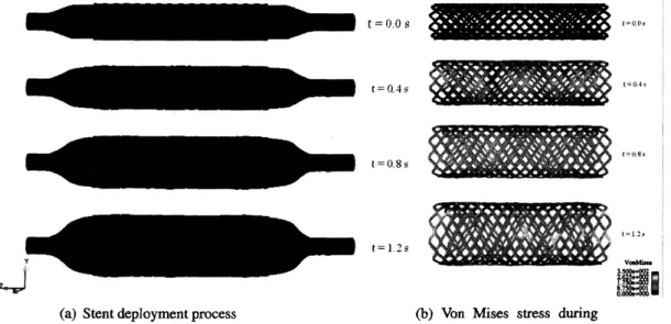
(a) Stentdeploymentprocess (b) Von Mises stress during stentdeployment
Figure 4: Stent deployment
physicallyopenthe channel of constricted arterial segments. During stenting,
a
catheter deliversa
balloon and
a
surroundingstenttothe location of theblockagearea.
The balloon deploysthestent,remainsinflated for30seconds andthenisdeflated. At the end of the
process,
the expandedstentis embedded intothe wallofthediseased arteryand holdsit
open.
Here,wemainlyfocusonthedeploymentprocessof balloon-expanding stents. In
our
previous work [16],we
builta
computer model and simulateda
balloon expandable stent interacting withits surrounding fluid using theimmersed finite element method. $A$catheter is located inside the
balloon toapply appropriatepressuretoinflatetheballoon. Theballoon hasalength of15 mm,
an
outerdiameter of 1.54mm, and
a
thickness of0.04mrn.
Both ends of the balloonare
fixed in alldirections. The balloons used for stenting
are
made ofverystiff polyamide(nyion)material[45, 46].Theballoonismodeled
as
hyperelasticmaterial with Mooney-Rivlin descriptioninthesimulation.Inthisparticularmodel,
we
use
theMedtronic AVEModular stentsS7(MedtronicAVE,Inc.,SantaRosa,$CA$, USA).Althoughthisstentis
no
longerbeenwidelyused,itisa
good representation ofa
typical geometrical shape of
a
stent,the modelcan
besimply modifiedtoother expandable devices.The stent,madeofwiresthat form
a
diamond shapehasan
outerdiameter of1.64mm.
The stentismade of 16 identical structural members with
a
total length of8mm
beforeits expansion. Thecross-sectionof thewirehas
a
width of0.08mm.
Finally, thestentismounted around the balloon.Thestentis placedatthecenterof the balloon. During theentire simulationthe inflation
pressure
isconstantandequals to 100$g/cm^{2}.$
Figure4(a) shows thedeployment ofthestentduringballoon expansionatdifferent time steps.
The
pressure
apphedonto the fluid inflates the balloon and the balloon providesa
forceonto thestent, which enables the stent to expand radially outwarduntil itcontacts theinner surface of the
arterywall.
The strength and the long term in-vivo performance of the stent
can
be determined from thelongitudinally alongthe stent andvariesduning deployment. Thesevalues
are
criticalforrecoiland failure analysis.3.3
Human vocal folds vibration
during
phonation
Voice is produced by the vibration of vocalfolds. The vocal folds
are a
pairof pliable strucmreslocated within the larynxatthe top of the trachea. The human vocal folds
are
roughly$10\sim 15$mm
in length and$3\sim 5$
mm
thick. The human vocal foldsare
laminated structures composed of fivedifferentlayers: theepithelium, the superficial layer(SLP), theintermediate layer(ILP),the deep
layerand thyroarytenoid muscle.
The geometry oftheself-oscillated vocal foldsmodelisshownin Fig. 5. Sincesoundis
gener-ated by thecompressionofair,theworkingfluidis taken
as
compressibleairgovemed by theidealgas
lawatroom
temperature. The density of thefluidis$\rho^{f}=1.3\cross 10^{-3}g/cm^{3}$ andtheviscosityofthefluidis$\mu=1.8\cross 10^{-4}g/cm\cdot s.$
The vocal fold muscle is considered
as
isotropic viscoelastic material. The vocal fold
is assumed to have layered structure, outside
cover
layer (red)and inside body layer(green).The
cover
layer is much softer than the bodylayer. For the
cover
layer the Young’smod-ulus is $E=10kPa$, whereas $E=40kPa$
for the body layer. The densities of both
cover
Figure5: 2-Dtwo-layerself-oscillated vocal foldsand body layer
are
assumedto be thesame as
model.$\rho^{s}=1.0g/cm^{3}$
.
ThePoisson ratio is $v=0.3.$Two vocal folds have the exact
same
geometry and material description, sit in the fluid channelsymmetric about the central line. $A$ constant total pressure boundary condition of$P_{in}=1kPa$
isapplied at the channel inlet and theoutflow boundaly is given atthe channel exit. No-slip and
no-penetration boundary conditions
are
appliedon
the channel walls andon
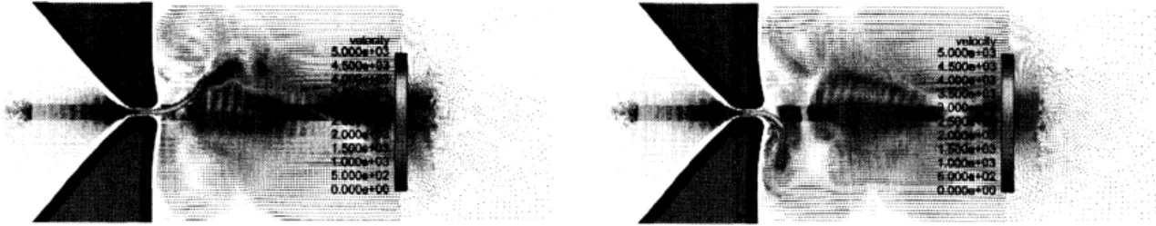
the vocal foldsurfaces.A snapshot of the fluid velocity field at two typical instances during
a
steady vibration cycleare
shown in Fig.6. Onecan
see
that the fluid field isnot symmetricaboutthe central line duringthevibration. The glottaljet tends to attach to
one
side of the vocal folds randoniy, whichistheso-called the Coanda effect” [47, 48].
The asymmetrical airflow
causes an
asymmetricalpressure
distributionin regionsnear
the vocalfoldsand changeinthevibrationpattem. Theminimum distancebetween thevocal fold surfaceand
the centrallineismeasuredto represent thehalf glottis width$(Gw)$, shownin Fig. 7, where$Gw_{up}$
and$Gw_{d\sigma wn}$ representtheopeningwidthfor theupanddown vocalfolds,respectively. Thisflgure
shows that the simulationcapturesthe vocalfoldstohave
a
repeatedopening and closingprocess.When the glottiswidthis
zero or
near-zero, then the vocal foldsare
closed, thereisno
air flowingthrough. The pressure starts to build up in the upstream of the vocal channel. As the pressure
increases, itstartstopushthe vocal folds to
open
andeventually reachesa
maximumglottiswidth,thehigh
pressure
is released. Thevocalfolds thenreturnbacktoits closedposition,
andthewholeprocess
restarts.4
Summary
In this paper,
we
briefiy reviewedsome
fluid-structure
interaction
(FSI) methods andal-gorithms that had been developed
over
thepast decade. The IFEM method is
a
nu-merical scheme thatadopts the
non-boundary-fitted mesh approach and fully couple the
fluid-structure interaction by interpolation the
inter-acting domains. The fluid and solid domains
are
solved independently using finite elementmethod and coupled with each other within
one timestepthroughfluid-structureinteraction
force. Three biomedical applications
are
illus- $T^{*}$trated in the
paper.
We show that the IFEMcan
modelsome
complicated biomedical apph- Figure7: Half glottis width oftopand bottomvo-cal folds.
cationsthatinvolve fluid-structureinteractions.
REFERENCES
[1] Peskin, C.S.,Numericalanalysisof blood flow in theheart,Journal
of
ComputationalPhysics25(1977)220-252
[2] McCracken,M.F. and Peskin,C.S., A vortexmethod forbloodflow throughheartvalves,Journal
of
Computational Physics35(1980) 183-205[3] McQueen,D.M. andPeskin, C.S.,Computer-assisteddesign ofpivoting-disc prostheticmitralvalves,
Journal
of
Computational Physics86(1983) 126-135[4] Peskin, C.S. andMcQueen, D.M., A three-dimensional computational method forblood flow inthe heart. I. Immersed elastic fibers in aviscous incompressible fluid,Journal
of
ComputationalPhysics81-2(1989)372-405
[5] Peskin,C.S. and McQueen,D.M.,Cardiacfluid dynamics. Critical Reviewsin Biomedical Engineering, SIAMJournalon
Scientific
and Statistical Computing20-6(1992)451-459[6] Peskin, C.S. andMcQueen, D.M.,Mechanical equilibrium determines thefractal fiber architecture of aortic heart valveleaflets,AmericanJournal
of
Physiology266-1 (1994)H319-H328[7] Peskin, C.S.andMcQueen, D.M., CaseStudiesin MathematicalModeling-Ecology, Physiology, and
Cell Biology, Prentice-Hall(1996)
[8] Zhang,L.T., Gerstenberger, A.,Wang,X. andLiu, W.K., Immersedfiniteelementmethod, Computer Methodsin Applied Mechanics and Engineering193(2004)2051-2067
[9] Zhang, L.T. and Gay, M., hmnersedfiniteelement method forfluid-structureinteractions,Journal
of
FluidS and Structures23(2007)839-857[10] Zhang, L.T.andGay, M.,Imposing rigidityconstraintsonimmersedobjects inunsteady flu\’id flows,
ComputationalMechanics42$(2\alpha)8)$357-370
[11] Wang, X. andZhang, L.T., Numerical method for fluid-structure interactions with sharpinterfaces: formulation andconvergencetests,ComputationalMechanics45(2010)321-334
[12] Liu, W.K., Liu, Y., Farrell, D.,Zhang,L.T.,Wang,S., Fukui, Y, Patankar, N.,Zhang, Y,Bajaj,C., Lee, J.,Hong,J., Chen,X. andHsu, H.,hnmersedfinite element methodanditsapplicationsto biological systems,ComputerMethods inAppliedMechanics andEngineering195(2006) 1722-1749
[13] Liu, W.K., Liu, Y,Zhang, L.T.,Wang,X.,Gerstenberger, A. andFarrell, D.,Immersedfiniteelement methodand applicationstobiological systems.Finite Blement Methods: 1970’s and Beyond, Intema-tionalCenter forNumerical Methods and Engineering,(2004)
[14] Liu, Y and Liu, W.K., Rheology of red blood cell aggregation in capillary bycomputer simulation, Journal
of
Computational Physics220(2006) i39-154[15] Liu, Y,Zhang,L.T.,Wang,X. andLiu, W.K.,CouplingofNavier-Stokesequations with protein molec-ular dynamics anditsapplication to hemodynamics, IntemationalJournal
for
NumericalMethods in Fluids46-12(2004) 1237-1252[16] Gay,M.,Zhang,L.T. andLiu, W.K.,Stentmodelingusingimmersedfiniteelementmethod, Computer
Methods in AppliedMechanicsand Engineering195(2006)4358-4370
[17] Zhang,L.T,Shearstressandshear-inducedparticleresidence in stenosed bloodvessels,International Journal
of
Multiscale Computational Engineering6(2008) 141-152[18] Zhang, L.T. and Gay, M., Characterizing left atrial appendage functions in sinus rhythm and atrial fibrillationusing computationalmodels,Journal
of
Bionechanics41 (2008)2515-2523[19] Gay, M. and Zhang,L.T.,Numerical studiesofhealthy, stenosed, and stentedcoronaryarteries, Inter-national Joumal
of
NumericalMethods in Fluids61(2009)453-472[20] Gay, M. andZhang, L.T., Numerical studies on fluid-structureinteractions of stent deployment and stented arteries, EngineeringwithComputers25(2009)61-72
[21] Mohd-Yusof, J.,Combinedimmersed-boundary/$B$-spline methods for simulations of flowincomplex
geometries,Center
for
TurbulenceResearchAnnualResearchBriefs
(1997)317-327, Stanford Univer-sity[22] Fadlun, E. A., Verzicco, R., Orlandi, P. andMohd-Yusof, J., Combined immersed-boundary finite-difference methods for three-dimensional complex flowsimulations,Joumal
of
ComputationalPhysics161(2000)35-60
[23] Verzicco, R., Iaccarino, G., Fatica, M. andOrlandi, P., Flow inanimpeller stirred tank using
an
im-mersed boundary method, Centerfor
Turbulence Research Annual ResearchBriefs
$(20(N)$ 251-261,[24] Verzicco, R., Fatica, M., Iaccarino, G. andMoin, P., Large eddy simulation ofaroadvehicle with drag-reductiondevices,AIAAJournal40No. 12(2002)2447-2455
[25] Ikeno, T. and Kajishima, T, Finite-difference immersed boundary methodconsistentwithwail
con-ditions for incompressibleturbulent flow simulations, Journal
of
Computational Physics 226 (2007)1485-1508
[26] Sato, N.,Kajishima,T., Takeuchi, S.,Inagaki, M.andHorinouchi,N.,ADirectDiscretizationApproach
nearWall BoundariesforaCartesian Grid Method(Considerationof Consistency between Velocity and PressureFields) Trans.JSME Ser.B79-800(2013)605-621
[27] Takeuchi, S., Yuki, Y, Ueyama, A. and Kajishima, T., 2010, A conservative momentum exchange algorithm for interactionproblem between fluid and deformable particles, International Journal
for
Numerical Methods in Fluids641084-1101[28] Sugiyama,K.,Nagano,N., Takeuchi, S., Ii, S.,Takagi,S.andMatsumoto,Y,Particle-in-cellmethod for fluid-structure interaction simulations of neo-Hookeantubeflows,TheoreticalandAppliedMechanics Japan59(20il)245-256
[29] Ii, S., Sugiyama, K., Takeuchi, S., Takagi, S. andMatsumoto, Y, An implicit full Eulerianmethod forthe fluid-structure interactionproblem, International Joumal
for
Numerical MethodsinFluids65(2011) 150-165
[30] Sugiyama, K., Ii, S., Takeuchi, S., Takagi, S. and Matsumoto, Y, A full Eulerian finite difference approach for solving fluid-structurecoupling problems,Journal
of
Computational Physics230(2011)596-627
[31] Nagano, N., Sugiyama, K., Takeuchi, S., Ii, S., Takagi, S. andMatsumoto, Y, Full-Eulerian finite-difference simulation of fluid flow in hyperelasticwavychannel,Journal
of
FluidScienceand Technol-ogy 5(2010)475-490[32] Sugiyama,K.,Ii, S., Takeuchi, S.,Takagi, S. andMatsumoto, Y,FullEulerian simulations of biconcave neo-Hookean particles inaPoiseuilleflow,ComputationalMechanics46-i (2010) 147-157
[33] Wang, X., Wang, C. and Zhang, L.T., Semi-implicit formulation of the Immersed $Fte$ Element
Method,Computational Mechanics49(2011)421-430
[34] Wang, X. and Zhang, L.T., Modified hnmersed Finite Element Method for solid-dominated fully-coupled fluid-structureinteractions, ComputerMethods in Computer Methods in Applied Mechanics andEngineering267(2013) i50-169
[35] Kajishima, T., Takiguchi, S., Hamasaki, H. andMiyake, Y, 2001, “Turbulencestructureof particle-laden flow in averticalplane channel duetovortex shedding”,JSME International Joumal SeriesB,
44-4526-535
[36] Yuki, Y., Takeuchi, S. and Kajishima, T., 2007, ”Efficientimmersedboundary methodforstrong in-teractionproblem ofarbitrary shape objectwith the self-inducedflow”,Joumal
of
FluidScienceand Technology,2-11-11[37] Kajishima, T. and Takiguchi, S., 2002, “Interaction between particle clusters and fluidturbulence”,
Intemational Joumal
of
Heatand FluidFlow,23-5639-646[38] Kajishima, T., 2004, ”Influence of particle rotation on the interactionbetween particle clusters and particle-inducedturbulence”,InternationalJournal
of
HeatandFluidFlow,25-5721-728[39] Nishiura,D.,Shimosaka,A., Shirakawa,Y andHidaka,J.,Hybridsimulationof hindered settling be-haviorofparticlesusing discreteelementmethodand direct numerical simulation(in Japanese),Kagaku KogakuRonbunshu,32-4(2006)331-340
[40] Ito,A., Takeuchi,S. and Kajishima,T.,Numericalanalysis of the effect of flexible wall elements
on
flowbehavior,Proc.6thEuropean Congress
on
Computational MethodsinAppliedSciences and Bngineering(ECCOMAS 2012),PublicationNo.$38\alpha$),Vienna, Austria, 10-14September,2012.
[41] Ito, A., Miyauchi, S., Takeuchi, S. and Kajishima, T., Numerical analysis of theinteractionbetween fluid and flexibleftbresclampedonelastic walls, Proc. 2ndInternational Conference onMechanical EngineeringResearch(ICMER 2013),Pahang,Malaysia, 1-3July,2013
[42]
HirC
C.W andNichols, B.D., Volume offluid (VOF)Method for the dynamics offree boundaries,Joumal
fo
Computational Physics39(1981)201-225[43] Ii, S., Gong,X.,Sugiyama,K., Wu, J.,Huang,H.and Takagi,S.,AfmEulerian fluid-membrane
cou-pling method withasmoothed volume-of-fluidapproach,Communications in Computational Physics 12-2(2012)544-576
[44] Ii, S., Sugiyama, K., Takagi, S., andMatsumoto, Y, A computationalbloodflow analysisin a
cap-illary vessel including multiple red blood cells and platelets, Joumal
of
Biomechanical Science and Engineering7-1(2012)72-83[45] Serruys, P.W. and Rensing, B.J., Handbook
of
coronary stents, Martin Dunitz, London, 4th edition(2002)
[46] Saab, M.A.,Applicationsofhigh-pressureballoons inthemedical device industry,AdvancedPolymers,
Inc.,Salem, NH, USA,(1999),
[47] Tao,C.,Zhang, Y, Hottinger, D.G. andJiang,J.J., Asymmetricairflowand vibrationinduced bythe Coandaeffect ina symmetricmodel of the vocalfolds,Joumal
of
the Acoustical Societyof
America122(2007)2270-2278
[48] Drechsel,J.S. andThomson, S.L., Influence of supraglottal structuresonthe glottal jet exitinga two-layer syngthetic, self-oscillating vocal fold model, Journal