酸素還元活性を有する
カーボンアロイ触媒の原子レベル設計
Atomic-level design for carbon alloy catalysts with oxygen reduction activity
松山 治薫
電気通信大学大学院 情報理工学研究科 博士 ( 工学 ) 学位申請論文
2020 年 3 月
カーボンアロイ触媒の原子レベル設計
Atomic-level design for carbon alloy catalysts with oxygen reduction activity
博士論文審査委員会
基盤理工学専攻 教授 中村 淳 ( 主査 ) 基盤理工学専攻 教授 一色 秀夫
基盤理工学専攻 教授 佐々木 成朗
基盤理工学専攻 教授 奥野 剛史
基盤理工学専攻 准教授 瀧 真清
著作権所有者
Copyright by
松山 治薫
Haruyuki Matsuyama
2020 年
Haruyuki Matsuyama Abstract
The oxygen reduction reaction (ORR) activity for the N-doped graphene was investi- gated using first-principles calculations within the density functional theory. Electro- catalytic activities were evaluated on the basis of the free-energy differences between reaction intermediates.
It has been shown that the graphene nanocluster (GNC) with a N atom around the center of the cluster exhibits a high value of the maximum electrode potential (UMax) comparable to platinum and the selectivity of reaction pathway, being a po- tential electrocatalyst for next-generation fuel cells. It has also been revealed that water molecules in the reaction field play the important role on the reaction selectiv- ity. On the other hand, the graphene nanoribbon (GNR) with a N atom inside the GNR exhibits a low UMax and no selectivity of reaction pathway. This means that a high ORR activity of N-doped GNC (N-GNC) is derived not from an effect of edge, but from a finite-size effect. The dependence of UMax on the size of a N-GNC was estimated from the free energy of the reaction intermediates. The volcano-shaped UMax trend was predicted as a function of the cluster size. As a result, it has been concluded that the C215H36N (UMax = 1.05 V) is the best size of N-GNCs for the ORR activity. Furthermore, the activation energy for the adsorption of the oxygen molecule was the highest in all reaction steps. Thus, the oxygen adsorption step is the rate-determining process for ORR. The current density per one reaction site was estimated as 10−41-10−43 A/cm2 from the activation energy.
Finally, the molecular design for the novel molecular catalyst (Fe phthalocyanine and its derivatives) was demonstrated.
In conclusion, we identified the best doping site and cluster size of the N-GNC and proposed the new derivative of the Fe phthalocyanine molecule. Our findings offer the guiding principles of the atomic-level design for carbon alloy catalyst with high ORR activity.
カーボンアロイ触媒の原子レベル設計
松山 治薫 概要
グラフェンやカーボンナノチューブ、フラーレンなどの低次元炭素材料は、未来のナノテ クノロジーを切り拓く素材として非常に注目されている。さらに、こうした低次元炭素材 料に異種元素をドープすることで電子状態を変化させ、新規デバイス材料としての展開を 図る研究も盛んに行われている。
環境に優しい次世代のエネルギーデバイスである燃料電池の幅広い普及のためには、カ ソードにおける酸素還元反応 (Oxygen Reduction Reaction: ORR) の高効率化が重要な 課題の1つである。現在、ORR触媒として広く用いられているのは白金などの貴金属で ある。しかし、貴金属触媒は高コストや希少性、低耐久性などの問題を多く抱えており、
反応高効率化による使用量の低減や貴金属フリー材料の開発が進められている。近年、窒 素を置換ドープしたグラフェンがORRに対する高い触媒性を有することが実験的に明ら かになった。地球上に豊富に存在する炭素と窒素からなり、ORRに対する触媒性を有す る窒素ドープグラフェンが実用化されれば、高コストや希少性などの問題を解決できる。
しかし、窒素ドープグラフェン表面上におけるORRの原子レベルでの具体的なアクティ ブサイト、エッジの形状やサイズが触媒性に与える影響、窒素ドープサイトと触媒性の関 係などは明らかになっておらず、これまで原子レベルでの触媒設計指針は確立されていな かった。
本研究では、密度汎関数理論に基づく第一原理計算を用いて、高いORR活性を有する カーボンアロイ触媒の原子レベルでの設計指針の提案を行う。Nørskovらにより考案され たComputational hydrogen electrode modelをベースとして、反応電位や反応経路の選 択性といった触媒能の電気化学的特性を熱力学的観点から評価した。主な反応経路として は、酸素分子が直接的に水分子に還元される「4電子経路」と、過酸化水素に還元される
「2電子経路」の2つを考えた。2電子経路で生じる過酸化水素はカーボン材料を腐食する 恐れがあるため、4電子経路での反応が望ましい。
エ ッジ に 囲 まれ た 有 限 サイ ズ の窒 素 ド ープ グ ラ フ ェン ナ ノク ラ ス タ ー (N-doped graphene nanocluster: N-GNC) 内の窒素原子位置を変化させ、ORR に対する触媒 性を評価することで、最適な窒素ドープサイトを探った。その結果、熱力学的に安定な GNCのエッジ部分ではなく面内に窒素をドープすることで、高い反応電位、反応経路の 選択性が得られることがわかった。その際、反応場に存在する水分子が反応経路の選択性
では、面内窒素ドープでは高い触媒性能は得られず、エッジ近傍でのみ反応経路の選択性 が発現することがわかった。したがって、N-GNC面内の高い触媒性能は、エッジ効果で はなく、クラスターの有限サイズ効果に起因することが示唆された。
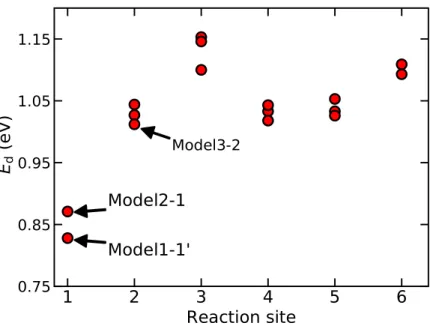
面内窒素ドープのN-GNCについて、反応電位や反応経路の選択性のクラスターサイ ズ依存性を評価した。その結果、クラスターサイズの増大に伴って反応電位が上昇し、半 径約14˚Aで4電子経路における反応電位が最大 (1.07 V) となることが予想された。そ れより大きなサイズでは反応電位が低下し、半径約20˚Aで反応経路の選択性も失われる ことがわかった。クラスターサイズが増大し、面内における有限サイズ効果が減退するこ とによって、触媒性能が低下する傾向は、エッジのない無限に広い窒素ドープグラフェン 面内で触媒性能が低いことと矛盾しない。さらに、反応速度に直結する活性化エネルギー はクラスターサイズの増大に伴って低下し、電流密度が増加する傾向があることも明らか にした。したがって、面内窒素ドープのN-GNC、特に半径約14˚A に近いC149H30Nや C215H36Nは、燃料電池のカソード電極触媒として、高い反応電位・電流密度に基づく高 出力、反応経路の選択性による高耐久性が期待できる。
最後に、本研究で用いる手法が、実際に作製可能な分子触媒の設計指針となり得るのか を確認した。ごく最近、FeN4 構造を中心に持つ鉄フタロシアニン (FePc) 分子の外側の 六員環に窒素を置換ドープした誘導体 (FeAzPc) が、ORRにおいて、高い反応電位と選 択性を有することが実験的に明らかになった。第一原理計算を用いて反応中間体の自由 エネルギーを計算し触媒性を評価したところ、確かにFePc よりもFeAzPcの反応電位 が高いこと、4電子経路に対する選択性を有することが示された。FeAzPcの高いORR 活性は反応中間体が FePc上よりも吸着しづらいことに起因する可能性も示した。FePc の中心金属原子、置換ドープする窒素原子の数や位置、電子状態変化をもたらす修飾基 の種類などのスクリーニングによって、さらに高性能なORR触媒の設計が期待できる。
N-GNCやFeAzPcにおける原子レベルでの触媒設計指針が示されたことは、さらに高い
ORR活性を有する新規カーボンアロイ触媒の最適化への道を拓くことになるだろう。
目次
第1章 序論 1
1.1 はじめに . . . 1
1.2 目的. . . 3
1.3 本論文の構成 . . . 4
第2章 酸素還元反応 (Oxygen Reduction Reaction: ORR) における触媒 6 2.1 燃料電池 . . . 6
2.2 ORRの反応経路 . . . 8
2.3 ORR触媒の現状 . . . 10
2.4 カーボンアロイ触媒 . . . 10
2.4.1 N-doped graphene . . . 11
2.4.2 N-doped graphene上のORR . . . 13
2.5 まとめ . . . 19
第3章 計算方法 (ORRの評価方法) 20 3.1 Computational Hydrogen Electrode (CHE) モデル . . . 21
3.2 活性化エネルギー . . . 26
3.3 電流密度 . . . 26
第4章 N-doped graphene nanocluster (N-GNC)におけるORR 27 4.1 計算モデルと計算条件 . . . 28
4.2 生成エネルギー . . . 30
4.3 自由エネルギーダイアグラム . . . 32
4.4 UMaxの窒素ドープ位置依存性 . . . 34
4.5 反応場に存在する水分子の影響 . . . 36
4.6 まとめ . . . 38 第5章 N-doped graphene nanoribbon (N-GNR) におけるORR 39
5.4 OOH吸着の安定化機構 . . . 47
5.5 反応中間体とπ*電子の相互作用 . . . 49
5.6 Pyridinic-NのORR . . . 52
5.7 まとめ . . . 55
第6章 N-doped graphene面内におけるORR 56 6.1 N-doped graphene sheet (N-GS) . . . 57
6.1.1 計算モデルと計算条件 . . . 57
6.1.2 自由エネルギーダイアグラム . . . 58
6.2 N-GNC面内におけるORR . . . 59
6.2.1 クラスターサイズ依存性 . . . 59
6.2.2 活性化エネルギー . . . 64
6.2.3 電流密度 . . . 67
6.3 まとめ . . . 69
第7章 鉄フタロシアニン系分子におけるORR 71 7.1 鉄フタロシアニン (Fe phthalocyanine: FePc) . . . 72
7.2 計算モデルと計算条件 . . . 73
7.3 O2 分子吸着 . . . 74
7.4 ORRに対する触媒性 . . . 75
7.5 まとめ . . . 78
第8章 結論と今後の展望 79 8.1 結論. . . 79
8.2 今後の課題と展望 . . . 81
8.2.1 窒素ドープグラフェン . . . 81
8.2.2 フタロシアニン系分子 . . . 82
付録A 第一原理計算 83
付録B N-GNRのORR 92
付録C Pristine GNCのORR 101
付録E ∆Gw/o 107 付録F FePc系分子の計算 (基底関数の違い) 108
謝辞 110
参考文献 111
研究業績 124
第 1 章 序論
本章では、研究動機となる社会的な背景および本研究の目的を述べ、本論文の構成を説 明する。
1.1 はじめに
近年、燃料電池や空気電池は環境に優しいクリーンなエネルギーデバイスとして注目を 集めている。化学エネルギーを電気エネルギーに変換する過程で二酸化炭素が発生しな い、重量エネルギー密度が高いなどの利点から、自動車や携帯デバイスに導入され始めて いる。しかし、自動車用燃料電池を筆頭にコスト面での課題が解決されておらず、普及に 歯止めがかかっている。現在、燃料電池などのカソードにおいて、酸素還元反応 (Oxygen reduction reaction: ORR) を促進するために白金などの貴金属が広く用いられている。
貴金属触媒は高コストや希少性、低耐久性などの問題を多く抱えているため、反応高効率 化による使用量の低減や白金フリー材料の開発が進められている。
近年、豊富に存在する炭素と窒素からなるN-doped grapheneが、高コストな貴金属の代 替材料の一つとして盛んに研究されている。様々な手法で作製されたN-doped graphene がORR に対する触媒性能を発揮することが実験的に明らかにされてきた [1–9]。窒素 の濃度、pyridinic-N やgraphitic-Nなど様々な局所構造の存在、欠陥構造など様々な原 子レベルの要素がORR に対する触媒性に影響を及ぼしていると考えられるが、作製さ
れたN-doped graphene にはそれらが混在しているため、実際にORR 活性を支配して
いる因子を実験的に特定することは困難である。一方、理論計算の立場からは N-doped
graphene上のORRのメカニズムについて、C–N結合の種類やエッジ効果の影響などが
議論されている [10]。しかし、様々な研究者が単発的にORR活性の高い構造を提案・主 張するのみで、ORR活性の支配因子にまで言及する例が少ないため、原子レベルでの触 媒設計指針は確立されていない。実験的にも理論的にもORR活性の高い構造を提案する ことは確かに重要ではあるが、視点を定めて系統的にORR活性の発現および向上メカニ ズムを解明することが理論計算にしかできない役割であると考えられる。
本研究では、ORR活性の支配因子を探る視点として、局所的な配置により電子状態を 著しく変化させる「窒素位置」、特異的な電子状態や高い化学的反応性を有する「エッジの
し、第一原理計算を用いて系統的にORR活性を評価することでN-doped graphene触媒 の原子レベルでの設計指針を提案する。具体的には100〜200程度の原子数からなる有限 サイズのN-doped graphene nanocluster (N-GNC) をモデルとし、エッジや面内といっ た窒素位置の違いがORR活性に与える効果を明らかにする。N-GNCと、無限にエッジ が広がるN-doped graphene nanoribbon (N-GNR)やエッジのない無限に広いN-doped graphene sheet (N-GS) を比較することにより、ORRにおけるエッジの有無や有限 (ク ラスター化) 効果を議論する。さらにこれまで重要視されてこなかった、ORR によって 生じる水分子が触媒活性 (特に反応経路の選択性) に及ぼす影響についても本研究で初め てその重要性を主張する。「窒素位置」、「エッジの存在」、「クラスターサイズ」とORR活 性の関係、反応場に存在する水分子が反応経路の選択性に及ぼす影響といった独自の視点 からN-doped graphene上におけるORR活性を系統的に理解することで、最終的に最適 な窒素位置やクラスターサイズを予測し、原子レベルでの触媒設計指針を提案する。過去 の研究で主張されてきたN-doped grapheneのORR活性に関する様々な議論の一端を収
束させ、N-doped grapheneにおける原子レベルでの触媒設計指針を提案することで、高
効率な新規貴金属フリーORR触媒の実現に向けた研究開発の一端を担う。新材料による ORR触媒のコストの低下が実現できれば、燃料電池や空気電池のさらなる普及が期待で きる。
1.2 目的
本研究では、密度汎関数理論に基づく第一原理計算を用いて、高ORR 活性を有する カーボンアロイ触媒の原子レベルでの設計指針の提案を目的とする。窒素位置、エッジ
の有無、grapheneのサイズなどの各要素がORR活性に及ぼす影響を系統的に理解する
ことに重きを置いて、N-doped grapheneのORR活性を評価する。具体的には、エッジ に囲まれたN-GNCの窒素原子位置を変化させ、ORRに対する触媒性 (反応電位や反応 経路の選択性) の窒素原子位置依存性を調べることで、最適な窒素ドープサイトを探る。
N-GNC 上のORRにおいて、反応場に存在する水分子の果たす重要な役割についても
議論する。エッジが無限に続くN-GNRにおけるORRの窒素原子位置依存性も評価し、
エッジの存在がORRに及ぼす影響を詳細に理解する。N-doped grapheneの面内に注目 し、0次元 (nanocluster) から2次元 (sheet) に至るまで、ORRに対する触媒性の変化 を調べる。N-GNCのORRのクラスターサイズ依存性を評価することで、最適なサイズ を提案する。最大電極電位に加えて、活性化エネルギーや電流密度を評価し、反応速度論 的観点からもORRに対する触媒性能を明らかにする。最後に、本研究で用いる手法が、
新たな分子触媒(鉄フタロシアニン誘導体)の設計に有用であることを示す。
1.3 本論文の構成
本論文は全8章で構成されている。図1.3.1は本論文の構成のフローチャートを示す。
第1章(本章) では、本研究の着手に至るまでの社会的背景から全体的な流れを述べた後、
本研究の目的と論文の構成を示している。第2章では、本研究における基礎的な事象とし て、燃料電池やORR、窒素ドープグラフェンなどの説明および先行研究例を紹介し、本 研究の位置付けを明確にする。第3章では、第一原理計算を用いたORR活性の評価方法 を述べる。第一原理計算の基礎的な理論は付録に示す。第4章〜第7章では、本研究にお ける結果と考察を述べる。第4章では、0次元のN-grapheneであるN-GNCのORRに 対する触媒性について述べる。窒素の位置や反応サイトの違いが触媒性に及ぼす影響を考 察するとともに、反応場に存在する水分子の重要性についても言及する。第4章の内容は 本論文の関連論文1として学術雑誌に掲載されている。第5章では、1次元のグラフェン ナノリボンに窒素をドープしたN-GNRのORRに対する触媒性について述べる。エッジ の存在や形状が触媒性に及ぼす影響を詳細に考察する。第5章の内容は本論文の関連論文 2として学術雑誌に掲載されている。第6章では、N-graphene の面内に注目し、エッジ の無い2次元のN-grapheneや様々なサイズのN-GNCのORRに対する触媒性を比較 する。最適なクラスターサイズを予測し、N-GNC触媒の原子レベルでの作製指針を提案 する。また、熱力学的なORR評価に加えて、活性化エネルギーなどの反応速度論的考察 も行う。第 4章〜第6章では一貫してN-grapheneにおけるORR について議論するが、
第7章では鉄フタロシアニン分子のORRに対する触媒性について考察する。実際に作製 可能な鉄フタロシアニン系分子のORRを実験的・理論的に評価し、フィードバックルー プを行うことで、高性能な新規ORR分子触媒となり得る鉄フタロシアニン誘導体の開発 指針を与える。実験結果と計算結果の整合性を考察することで、ORRに関する現行の理 論的評価手法の有用性を示すとともに、本研究の中心テーマであるN-garpheneにおける ORR活性の考察の妥当性を保証する。最後に、第8章で本研究を通して得られた知見を 結論としてまとめ、今後の展望についても述べる。
図1.3.1 本論文の構成
第 2 章 酸素還元反応 (Oxygen Reduction Reaction: ORR) における触媒
本章では本研究における基礎的な研究背景として、ORRおよびその触媒に関する先行 研究例を述べる。
2.1 燃料電池
燃料電池とは、水素、メタノール、空気などの流体を燃料として外部から連続的に供給 し、水などの反応生成物を連続的に回収する過程でエネルギーを取り出すシステムであ る。燃料電池は、化学エネルギーを直接電気エネルギーに変換するという点では、通常の 化学電池と同様の機能を提供する。しかし、化学電池が反応活物質の閉鎖系であるのに対 し、燃料電池は反応活物質を外部から連続的に取り込む開放系であるという点で異なる。
電気化学デバイスである燃料電池は、熱機関におけるカルノー効率の制限を受けないた め、理論的には100%近いエネルギー変換効率が期待できる [11]。また、小規模でも効率 が落ちないことや、低温動作の方が理論効率が高いなどの利点からも燃料電池は古くから 注目されてきた。現在の燃料電池の主な課題は、「触媒活性の向上」、「耐久性の向上」、「コ ストの低減」の3つである。
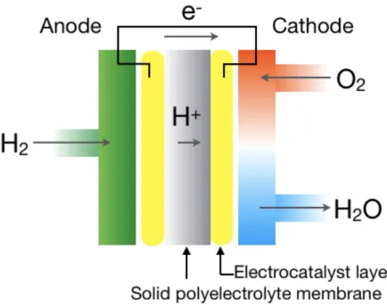
図2.1.1 固体高分子形燃料電池の模式図
固体高分子形燃料電池は、イオン電導性を有する高分子膜を電解質として用いる燃料電 池である。図2.1.1は、固体高分子形燃料電池の模式図を示す。まず燃料極 (anode) で水 素が燃料として供給され、水素酸化反応 (H2 → 2H++ 2e−) より、水素イオンと電子に 分解される。その後、水素イオンは電解質、電子は外部導線を通って空気極 (cathode) に 移動する。Cathodeでは、空気中から取り込んだ酸素と、移動してきた水素イオンと電子 がORR (O2+ 4H++ 2e− →2H2O) を起こし、水が発生する。これらの反応から、理論
上は約 1.23Vの電位が得られると考えられているが、実際には電極での損失などにより
0.7V程度しか得られない [11]。現在cathodeでの主要な ORR触媒は白金等の貴金属で ある。Anodeでの水素酸化反応の反応速度は十分であるが、cathodeでのORRの反応速 度は非常に遅く、反応を促進するためには大量の白金を必要とし、コストが上昇する。ま た、高電位にさらされるcathodeにおいて反応速度が遅いことは耐久性にも悪影響を与え る。したがって、cathodeでの酸素還元反応に対する新たな触媒材料が求められている。
2.2 ORR の反応経路
図2.2.1 酸素還元反応のスキーム図
ORRには、主に「直接4電子経路」、「連続4電子経路」、「2電子経路」の3つの反応 経路がある。ORRのスキームは1976年にWroblowaらによって一般化された [12]。図 2.2.1は、酸性環境におけるORR のスキーム図を示す。4電子経路はO2 をH2Oに、2 電子経路はO2 をH2O2 に、それぞれ還元する経路である [4, 12–21]。直接4電子経路で は、O2分子が4つの電子を伴って、直接的にH2O分子に還元されるのに対し、連続4電 子経路では、O2 分子が2つの電子を伴ってH2O2 分子に還元された後、さらに2つの電 子を伴ってH2Oに還元される。H2O2分子が吸着せず脱離すれば、2電子経路となる。2 電子経路での反応は、反応電子数が4電子経路の半分であり、電力効率が良くないため、
すべてのO2分子が直接4電子経路で還元されることが理想である。また、2電子経路に よって生じる H2O2 はカーボン材料を腐食する可能性が高いため、本研究で対象とする
N-doped grapheneのようなカーボン系触媒においては4電子経路に対する選択性は非常
に重要な機能である。カーボン系触媒では、H2O2 は安定には吸着しないことが知られて いるため、本研究においては連続4電子経路は扱わない。以降で「4電子経路」は「直接 4電子経路」を意味する。
4電子経路と2 電子経路の反応経路の選択性は、金属ベースの触媒でこれまで多く議 論されてきた。反応経路の選択性は、金属やその表面の方位に強く依存することが知ら れており [22]、表面における反応中間体の吸着の安定性に支配されている。しかし、反 応選択性の発現については理解が不十分である。また、反応中間体の安定性は、反応場 に存在する水の影響を受けることが知られており、例えば、Pt触媒表面では、ORRの
中間体は水分子によって安定化することが示唆されている [23, 24]。本研究で対象とする
N-graphene については、ORRの始状態である O2 分子の吸着の安定性が反応場の水分
子に強く影響を受けることが報告されている [20]。さらにORRによって生成される水分 子がORR活性に強い影響を及ぼすことも示唆されている [25]。しかし、反応場に存在す る水分子が反応経路の選択性に与える影響は明らかにされていない。本研究では、反応場 に存在する水分子の効果にも注目し、ORRにおける4電子経路と2電子経路の反応経路 の選択性を議論する。
2.3 ORR 触媒の現状
燃料電池や空気電池のcathode におけるORR を促進するために、現在は主に白金な どの貴金属が電極触媒として使用されている。特に、カーボン担体に白金を分散担持した Pt/C が最も一般的なORR 触媒である。Pt粒子を分散して使用することで反応表面積 を大きくし、Pt バルクよりも使用量を低減している。しかし、Ptの希少性を考えると、
さらなる使用量低減と代替材料の開発が必要である。使用量低減のために、Pt などの貴 金属をナノ粒子化する研究が行われている [26–30]。Ptと他の金属元素を組み合わせた材 料のORR活性が高いことも報告されている [26, 29–39]。代替材料としてナノカーボン材 料をベースとしたカーボンアロイ触媒の研究も盛んに行われている。
2.4 カーボンアロイ触媒
カーボンアロイ触媒は炭素原子の集合体をベースとした触媒材料であり、貴金属の使 用量低減や代替材料となることが期待されている。金属単原子をドープした炭素材料が ORR 活性を示すことが報告されている [40–44]。Snをドープしたgrapheneなどが高い ORR活性を有することも示唆されている [41]。FeとN-grapheneを組み合わせた材料が Ptに匹敵するORR 活性を示すことも報告されている [45]。一方、完全なメタルフリー 触媒として、窒素やホウ素などの非金属原子をドープしたナノカーボン材料も盛んに研究 されている。特に、窒素をドープしたナノカーボン材料は ORR に対する触媒性を有す ることが実験的に明らかになっており [6, 46–52]、豊富に存在する炭素と窒素で構成され ている点も含めて注目を集めている。本節では、ナノカーボンの中でもgrapheneに注目 し、N-doped grapheneの触媒研究の近年の進展を概観する。
2.4.1 N-doped graphene
一般にgrapheneへのドーピングには、graphene表面にガスや有機分子などを吸着さ
せる表面ドーピングと、graphene格子内の炭素原子を窒素原子などで置き換える置換型 ドーピングの 2種類がある。置換型ドープgrapheneの一つである N-doped graphene は、燃料電池触媒、電子デバイス[53]、センサーなど応用性が高く、その物性に関する様々 な研究がされている。ドープされた窒素原子近傍の炭素原子のスピン密度や電荷分布が変 化することでgraphene表面上に化学反応性の高い領域ができ、ORR触媒などへの応用 が期待されている。ORR における反応サイトを増加させるためには、1つのgraphene あたりの窒素の数を多くすることや、窒素を含む小さなgrapheneを数多く作るなどの方 法が考えられる。
200 nm
図2.4.1 N-graphene nano dot のAFM 像[54]
図2.4.2 N-grapheneの局所構造[10]
図2.4.1は、PECVD (plasma-enhanced chemical vapor deposition) 法で作製された N-doped graphene nano dot の AFM (Atomic Force Microscope) 像を示す。対称性 の高いのgraphene nanoclusterの作製に成功しており [54–61]、同様に、クラスター状 のN-doped graphene も作製されている [54]。Graphene格子内にドープされた窒素原 子は主に、”graphitic-N”、”pyridinic-N”、”pyrrolic-N”と呼ばれる3つの結合種を持つ ことが知られている [10]。図2.4.2は、3つの結合種を含むN-doped grapheneを示す。
ずれも通常の grapheneとは異なる性質を示す。Pyridineを原料としてNi (111) 面上で 結晶成長させたN-doped grapheneにはgraphitic-Nとpyridinic-Nが混在していること が報告されている [62]。一般的に、N-doped grapheneにおいて、ORRの反応サイトは 窒素最近接の炭素原子上だとされている。したがって、N-doped graphene中に含まれる 局所的なC–N結合の違いに依存して、ORR活性が変化することは十分考えられる。
一般的に、窒素はgraphene面内よりも化学的反応性の高いエッジにドープされやすい ことが明らかになっている [72–75]。理論計算からも窒素のドープ位置のエッジからの距 離と熱力学的安定性が評価されている。図 2.4.3は、N-doped graphene nanoribbonの 生成エネルギーと窒素のエッジからの距離の関係性を示す [75]。エッジ部分に窒素は非常 にドープされやすく、面内との生成エネルギー差は 1eV以上であり、熱力学的に窒素を 面内にドープすることが非常に困難であることが示唆されている。
exothermic. Note that the magnitude of the change in DE
ffor N is greater than that for B.
What has to be noted is that the increase in the formation energy with the distance from the edge is not monotonic;
two independent curves arise for the odd- and even-numbered sites. Such an odd-even trend in the formation energy has also been reported in previous stud- ies.
39,41However, the mechanism of the site-dependent sta- bilization has not been clarified yet. It is important to note that the bipartite lattice like graphene has two equivalent sublattices. If the symmetry is broken by the introduction of zigzag edges, the two sublattices, the odd- and even- numbered sites, become non-equivalent to each other. Such a sublattice-dependent stabilization mechanism is discussed in Sec. III B.
B. Mechanism of the stabilization
In this section, we investigate the mechanism for doping site-dependent stabilization. It is well-known that ZGNR has localized states at the zigzag edges, and their electronic dis- persion along the ribbon axis is partly flat at the Fermi
level.
6,10The existence of these edge states is also confirmed by first-principles calculations.
11Figure 3 shows the band structure and density of states (DOS) of pristine ZGNR as well as the partial DOS for the outermost C atom. For ZGNR with finite ribbon width, an antiferromagnetic coupling between two edges leads to the band gap opening.
7,12Hereafter, we define the Fermi level as the center of the valence band maximum and the conduction band minimum.
As shown in Figure 3, we can find two flatbands just below and above the Fermi level; these are the so-called edge states. Figure 3(d) shows a schematic energy diagram for the edge state. For the occupied state, the b -spin ( a -spin) state is localized at the A (B) side of the edge, and vice versa for the unoccupied state. Note that these edge states have significant amplitude only at the odd-numbered sites.
Figures 4(a), 4(b), and 4(c) show the band structure, the total DOS, and the partial DOS of the N atom at site 1 for N-doped ZGNR, respectively. A noticeable difference from
FIG. 2. Formation energies for (a) the N-doped and (b) the B-doped ZGNR.
The dashed horizontal line indicates the formation energy of the N or B atom in the 2D graphene. DE in the right y-axis indicates the difference in formation energies between ZGNR and 2D graphene.
FIG. 3. Electronic structure of pristine ZGNR. (a) Band structure of ZGNR.
Red and blue lines indicatea- andb-spin states, respectively. (b) Total DOS of ZGNR. (c) Partial DOS for the 2pz orbital of the outermost C atom (site 1). The dashed ellipse highlights the energy level for the edge state localized at the A side fora-spin. (d) Schematic energy diagram of the edge state. The probability density for each energy level is also shown. Red and blue colors indicatea- andb-spin states, respectively.
214301-3 Uchidaet al. J. Appl. Phys.120, 214301 (2016)
Reuse of AIP Publishing content is subject to the terms at: https://publishing.aip.org/authors/rights-and-permissions. Download to IP: 130.153.8.18 On: Sat, 03 Dec 2016 08:16:06
図2.4.3 N-doped graphene nanoribbonの生成エネルギーの窒素位置依存性 [75]
2.4.2 N-doped graphene 上の ORR
近年、N-doped grapheneがORR に対する触媒性を有することが実験的に明らかに
なった[1–9]。図2.4.4は、N-doped grapheneのLSV (linear sweep voltammetry)を示 す [3]。何もドープしていないgrapheneでは、ORR活性を示さないが、窒素をドープす ることでORR活性が発現することがわかる。さらに白金触媒に匹敵するORR活性を有 するN-doped grapheneも報告されている. [1, 2, 7–9, 63–65]。
図2.4.4 N-grapheneのLSV [3]
ORRに対して、C–N 結合の種類、局所的な活性サイトの存在、エッジ効果が及ぼす 影響などに関して様々な議論が展開されてきたが、N-doped graphene上のORR にお ける原子レベルでのメカニズムについて見解の一致は見られてこなかった。多くの研究 者たちが、実験をもとに、pyridinic-Nを含むN-doped grapheneが高いORR活性を有 すると主張している [2–6, 64]。Wu らは、 g-C3N4 から N-doped grapheneを作製し、
pyridinic-Nが活性サイトとなって、過電圧が減少することを示している[4]。Zengらは、
エッジにおけるpyridinic-Nとgraphitic-Nの含有率が高いグラファイトライクカーボン が高いORR活性を示すと主張している [6]。Pyridinic-Nに隣接する炭素原子が、ORR における始状態であるO2分子の吸着サイトとなり、 ORRの活性サイトとなることも報 告されている [5]。対照的にGengらは、graphitic-NがORR活性の高さを決定づける支 配要素であると主張している [9]。
このように、C–N結合種という1点に関しても実験的にN-doped graphene上のORR のメカニズムを理解するのは非常に困難で、理論的なアプローチからN-doped graphene
15
一般的に、窒素はgraphene 面内よりも化学的反応性の高いエッジにドープされやす いことが明らかになっていることから [72–75]、エッジ近傍や欠陥における ORR 活性 に関する研究が数多くなされている [13, 21, 65–67, 76–82]。Chaiらは、欠陥構造により ORR活性の向上が可能であると主張している [67]。また、Wangらは、窒素だけでなく ホウ素を共ドープすることで ORRをさらに活性化できると報告している [68]。無限に 長いエッジを有するN-doped graphene nanoribbonが高いORR活性を示すことも明ら かにされている [63, 81]。エッジにドープした窒素近傍の炭素原子がORRの活性サイト となることも示唆されている [21, 66, 77–79]。図2.4.5、図2.4.6は、N-doped graphene nanoribbon [81]やN-doped graphene dot [66]のエッジでのORR活性を示す。エッジ から2番目の位置にドープされた窒素に隣接するエッジ炭素原子で高いORR活性を示す ことが示唆されている。
O!2þ4Hþþ4e#!2O!þ4Hþþ4e# ðR2Þ 2O!þ4Hþþ4e#!O!þOH!þ3Hþþ3e# ðR3Þ O!þOH!þ3Hþþ3e#!O!þH2OðaqÞ þ2Hþþ2e# ðR4Þ O!þ2Hþþ2e#!OH!þHþþe# ðR5Þ
OH!þHþþe#!H2OðaqÞ ðR6Þ The whole dissociation mechanism included O2adsorption and dissociation steps and four net CPET steps. The minimum energy path of O2dissociation was studied using LST/QST tools in DMol3 code, while theDGof every CPET step was calculated using the CHE model.Fig. 3shows the energy diagrams of ORR via the disso- ciation mechanism on NG-doped zigzag GNRs. It was found that the dissociation of O2molecule into two separated O atoms required an energy barrier of 0.16 eV, which was very easy to overcome at room temperature. After O2dissociation, the calculatedDGvalues
for the four CPET steps were#1.92 and#0.74 eV for the two reduc- tion steps of O atom to OH, and#0.73 and#0.47 eV for the two steps of H2O formation steps at an electrode potential ofU= 0 V.
When an ideal electrode potential of 1.23 V was applied, the energy levels of four CPET steps were shifted up by 1.23 eV. At U= 1.23 V, theDGvalues of four sequential CPET steps changed to#0.69, 0.50, 0.49 and 0.76 eV, respectively. It becomes evident that formation of the second H2O was the rate-determining step in dissociation mechanism at high potential region. This suggested that the formation of second H2O molecule represents the highest resistance.
The association mechanism proceeded in a similar manner to the dissociation mechanism, except for(R2) and (R3). In contrast to the dissociation mechanism, O2first reacted with proton and electron to form OOH in association mechanism. The structure of OOH on N-doped GNRs was checked carefully. It was observed that OAO bond dissociated to form O and OH spontaneously, when H was introduced to O2(As shown inFig. S2 in supporting informa- tion). Thus,(R2) and (R3)could be substituted by the following step:
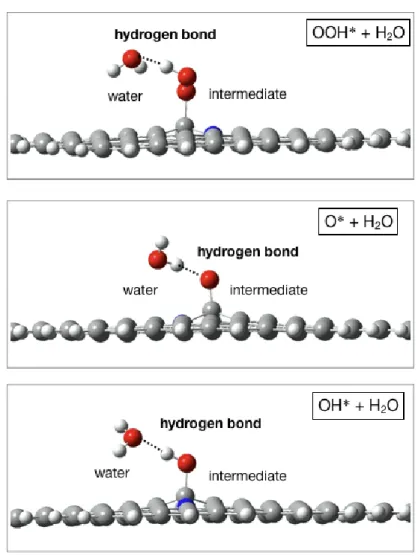
O!2þ4Hþþ4e#!O!þOH!þ3Hþþ3e# ðR7Þ As shown inFig. 4, the association mechanism showed a sub- stantially different energy diagram for ORR on NG-doped zigzag GNRs in association mechanism. At electrode potential U= 0 V, the calculatedDGvalues of five elemental steps were#0.88 eV for O2adsorption,#1.92 eV for the reduction of O2to adsorbed O and OH, #0.98 eV for the formation of first H2O molecule, Fig. 2.Preferred adsorption structures of (a) O2, (b) O, (c) OH, and (d) H2O on NG-doped zigzag GNRs. (e) Partial density of states (PDOS) for O2adsorbed on NG-doped zigzag GNRs.
Table 1
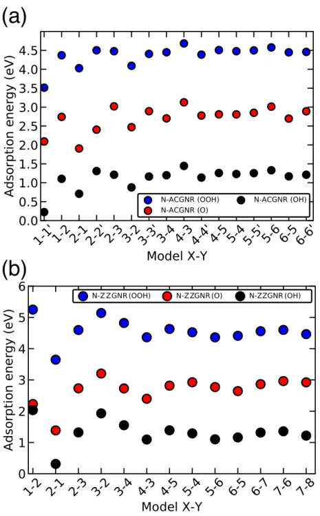
Adsorption energies (Ead) of ORR intermediates on N-doped GNRs. All results are in unit of eV.
Ead O2 OOH O OH H2O
NG-doped zigzag GNRs 1.09 1.27 4.45 2.69 0.07
NP-doped zigzag GNRs #0.03 – – – –
NG-doped armchair GNRs #0.11 – – – –
NP-doped armchair GNRs #0.33 – – – –
Fig. 3.Free energy diagram of ORR on NG-doped zigzag GNRs through O2dissociation mechanism with structures of selected intermediates.
図2.4.5 N-graphene nanoribbonのエッジでのORR活性[81]
図2.4.6 N-graphene dotのエッジでのORR活性 [66]
16
図2.4.7 は、N-doped graphene nanoribbon の酸素発生反応 (Oxygen evolution re-
action: OER) およびORR における過電圧の反応中間体の自由エネルギー依存性を示
す [78]。Liらの計算によって、窒素のドープ位置やエッジの形状によってOERやORR に対する触媒性能は変化すること、エッジ近傍の触媒性能が高いことを示唆された。
oxidation just above the equilibrium potential, but requires all the four charge transfer steps to have reaction free energies of the same magnitude at zero potential (i.e., 4.92 eV/4 = 1.23 eV). This is equiv- alent to all the reaction free energies being zero at the equilibrium potential, 1.23 V. Since there is a scaling relation between OH! and OOH!, this set a constraint on DG2and DG3, i.e., DG2+DG3= DGOOH*"DGOH*= 3.177 eV, resulting a lower limit of OER overpotential. When DG2=DG3= (GOOH*"GOH*)/2 = 1.589 eV, the
OER overpotential has the minimum value,
gOERlimit¼1:589—1:23¼0:359 V. For ORR, there is also a lower limit of the overpotential. The overall free energy of reaction (2)–(5)is 4.92 eV, leading toDG1+DG2+DG3+DG4= 4.92 eV. Since DG2+ - DG3= constant, we derived that DG1+DG4= constant. When DG1=DG4= 0.871 eV, the ORR overpotential has its minimum value,gOERlimit¼1:23—0:871¼0:359 V.
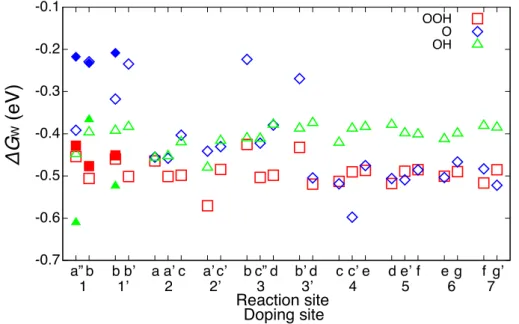
To derive the minimum overpotential in N-doped graphene sys- tems, we calculated the overpotenials for different reaction sites on different structures employing a descriptorDG0O!"DG0HO!:Fig. 4(a) shows the volcano plot,i.e., overpotentialgOERversus the descrip- tor for various reaction sites on armchair and zigzag graphene structures. From this theoretical analysis, Model A2–3 is identified to have a minimum OER overpotential (gOERmin ¼0:405 V). For the ORR activity, previous results showed that the pathway(6), (7a), (8a), and (9)had close reaction enthypl distribution for each steps [17], which would result in small overall ORR overpotentail. Using similar methods described above, we calculated the overpotenials of this ORR pathwaygORR for various reaction sites on armchair/
zigzag graphene structures. A volcano plot was made using the descriptorDG0OH!. As shown inFig. 4(b), among the structures stud- ied, Model A2–1 has the lowest ORR overpotential, which was esti- mated to be 0.445 V. These values of the overpotential for ORR and OER are comparable to those of Pt containing catalysts ($0.4 V for OER on PtO2-rutile and$0.45 V for ORR on Pt[34]), indicating that
N-doped graphene as bifunctional catalysts may have as good per- formance as its counterparts. To determine at what condition the OER or ORR can spontaneously occur, we calculated the free energy under different electrode potentialsU.Fig. 5shows the diagrams of OER substeps on reaction site A2–3 and ORR substeps on reaction site A2–1. For sites on A2–3, the OER is uphill when the electrode potential is 0 V. AtU= 1.23 V, an ideal water splitting potential, the transformation of OOH!to O2becomes downhill, but the reactions (2)–(4)are still uphill. Only when the potential increases to 1.635 V (i.e., 0.405 V in overpotentail), can all the elementary reaction steps become downhill. So, 1.635–1.23 = 0.405 V is the overpotentail for this reaction site, and the transformation of O!to OOH!is the rate determination step. Since the OER overpotential is reduced by nitrogen doping, the above OER is facilitated overall by the N- doped graphene.
For ORR on A2–1, when the electrode potential is 0 V, the ORR substeps(6), (7a), (8a), and (9) are all downhill, corresponding to a short circuit condition of fuel cells. As the electrode potential increased to 1.23 V, the reaction steps (7a), (8a), and (9) are all uphill, corresponding to an open circuit condition of fuel cells.
Since the reaction (6), adsorption of O2 as OOH! becomes uphill while other subreactions still keep downhill at U= 0.785 V, the adsorption of O2as OOH! must be the rate determination step in ORR. Thus, the minimum ORR overpotential is 1.23–
0.785 = 0.445 V.
The most active sites identified above are attributed to the redistribution of surface charge induced by the incorporation of nitrogen atoms into carbon lattice. As shown inFig. 6, some carbon atoms become positively charged while others are negative after a nitrogen atom is doped on the graphene. Those carbon atoms with positive effective charge will facilitate the adsorption of some spe- cies with negative charges [17]. However, if the adsorption free energy of O!is too high due to high positive charge or edge effect,
(a) (b)
Fig. 3.(a) Adsorption energies of OOH!versus adsorption energies of OH!and (b) adsorption energies of OH!versus adsorption energies of O!on different sites of armchair and zigzag graphene nanoribbons.
(a) (b)
Fig. 4. Volcano plots for (a) OER and (b) ORR on different sites of armchair and zigzag graphene nanoribbons.
図2.4.7 N-graphene nanoribbonのOERおよびORRに対する触媒性 [78]
図2.4.8は、エッジ近傍におけるpyridinic、graphitic、pyrrolic-NというC–N結合種 とORRの過電圧の関係を示す [79]。Saidiらは、 窒素ドープナノカーボンのエッジにお いて、pyridinic-Nとgraphitic-Nの両方が活性サイトの支配要素となると主張している。
Pyridinic-Nが最も過電圧が低くORR活性が高いが、graphitic-Nもpyridinic-Nに次ぐ 高いORR活性を有することが示唆された。
Oxygen Reduction Electrocatalysis Using N ‑ Doped Graphene Quantum-Dots
Wissam A. Saidi *
Department of Chemical and Petroleum Engineering, University of Pittsburgh, Pittsburgh, Pennsylvania, 15261, United States
*
SSupporting Information
ABSTRACT: First-principles investigations of the electro- catalytic activity toward the four-electron oxygen reduction- reaction in N-doped graphene quantum dots reveal that pyridinic and graphitic nitrogen are the most active sites with overpotentials of 0.55 and 0.79−0.90 V, respectively. This agrees with experimental fi ndings. Our calculations account for van der Waals interactions, solvent e ff ects, and describe the electrochemistry using standard hydrogen electrode model.
The results show correlations between OH * , OOH * , and O * binding energies that impose a lower limit on the oxygen reduction overpotential.
SECTION: Energy Conversion and Storage; Energy and Charge Transport
T he oxygen reduction reaction (ORR) and its reverse reaction, oxygen evolution reaction (OER), are among the most studied electrochemical reactions for fundamental reasons as prototypes of four electron transfer reactions, and for technological relevance in renewable energy production.
Speci fi cally, both ORR and OER are at the center of many applications in electrochemical energy conversion processes including polymer electrolyte membrane fuel cells (PEMFCs), direct-solar and electrolytic water-splitting devices,
1and metal−
air batteries.
2However, a key element for the commercializa- tion of these reactions is the need of an e ffi cient and cost- e ff ective catalyst that solves their slow kinetics at the oxygen electrodes, namely, the cathode in fuel cells and the anode in electrolyzers. For example, Pt-based alloys are among the best catalysts in PEMFCs despite the fact that the fuel cells have a signi fi cant power loss due to a low operating voltage of 0.7 V as measured with respect to standard hydrogen electrode (SHE);
this is only 57% of the available free energy.
3,4Additionally, and more importantly, large amounts of the precious metal Pt are needed to boost the cathode kinetics that are signi fi cantly slower than the hydrogen evolution at the anode.
Currently, nanocarbon materials are heavily researched not only as a support to e ffi ciently disperse catalytic particles,
5,6but also as novel and cheap catalytic materials.
7,8In particular, N- doped carbon materials have attracted a lot of interest as a potential metal-free catalysts for ORR.
9−22Matter et al. showed ORR activity using N-doped carbon nano fi ber, which was particularly high in the presence of Fe.
9,11Gong et al.
demonstrated high ORR activity in N-doped carbon nanotubes as well but without any metals.
17Several groups have reported that N-doped graphene (N-GA) exhibited catalytic activity toward ORR in both alkaline
18,19and acidic
14,23,24media. Also,
recently, N-doped graphene quantum-dots (N-GQD) showed ORR activity with a greater potential than Pt-based PEMFCs, but nevertheless led to currents comparable to that of Pt.
25,26In these N-GQDs, and in contrast to nitrogen-doped nano- carbons,
27the ORR activity did not show a positive correlation with the nitrogen content.
The ORR mechanism in N-doped nanocarbons including the active site is still a matter of debate despite prior studies.
9−12Experimentally, Matter et al. concluded that pyridinic nitrogen is the only active site, while Subramanian reports that both pyridinic and graphitic nitrogen can activate the ORR process.
9,14On the basis of density functional theory (DFT) investigations, Okamoto proposed that the complete four- electron ORR activation can be achieved with an adequate binding energy of the oxygen atom on multiple N-doped graphitic sites.
15Ikeda et al. also concluded similarly that graphitic nitrogen was the active site based on oxygen adsorption barriers and energetics of the subsequent ORR processes.
12Recently, Kim et al. proposed that the ORR activation initiates at the outermost graphitic nitrogen site with the fi rst reduction step; however, the latter graphitic nitrogen becomes pyridinic-like in the next reduction steps via the ring- opening of a cyclic C−N bond.
21In this Letter, we investigate the ORR activity in N-GQDs and the e ff ect of the nitrogen doping-site chemistry on the e ffi ciency of the electrochemical reaction. The ORR can be carried out incompletely using a two electron pathway that reduces O
2to H
2O
2, or completely using a four-electron
Received: September 27, 2013 Accepted: November 20, 2013 Published: November 20, 2013
Letter pubs.acs.org/JPCL
© 2013 American Chemical Society 4160 dx.doi.org/10.1021/jz402090d|J. Phys. Chem. Lett.2013, 4, 4160−4165 図2.4.8 ORRにおける過電圧とC–N結合種の関係[79]
近年、エッジに囲まれたクラスター状のN-grapheneがORRに対する触媒性を有する ことが報告された [8, 16, 84, 85]。クラスター状にすることにより被表面積が増大し、ORR 活性が増大すると考えられる。また、grapheneのクラスターはサイズや形状によって電 子状態が変化することが明らかになっている [59]。クラスター状のN-graphene のエッ ジ近傍のORR 活性のクラスターサイズ依存性が理論計算によって評価された [86]。図 2.4.9は、N-grapheneのエッジ近傍のORR活性を示す。C23H12N, C53H18N, C95H24N とクラスターサイズが大きくなると、過電圧は0.79, 0.88, 1.05 Vと上昇することが示唆 された。クラスターサイズの増大に伴って、反応中間体とエッジ炭素原子との結合が強く なり、反応がスムーズに進行しなくなることが原因として考察されている。エッジ近傍に ついては、クラスターサイズに対する系統的な理論計算が行われているが、クラスターの 面内については系統的な理解は得られていない。
図2.4.9 クラスター状のN-grapheneのエッジ近傍のORR活性 [86]
当てて、ORR 活性が評価されてきた。その一方で、表面積の大きい面内も利用するこ とができれば、反応サイトを増やすことができ ORR活性をさらに向上できると考え、
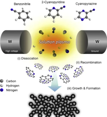
graphene面内に窒素を積極的に取り込むための手法も研究されてきた。近年、Solution
Plasma prosess [87]を用いて、非熱平衡状態下でナノカーボンを合成する手法が開発さ
れた。図 2.4.10は、Solution Plasmaの模式図を示す。ピリジンなどの窒素を含むカー ボンモノマーを熱力学過程を経ずに液中低温プラズマ (solution plasma) で重合すること により、窒素やホウ素を面内に積極的に取り込んだナノカーボンの作製が試みられてい る [1, 88, 89]。
(l¼0.154 nm) operating at 40 kV and 40 mA (1.6 kW). Raman spectra were recorded on a JASCO NRS-5100 spectrometer with a laser-excitation wavelength of 532 nm. X-ray photoelectron spectroscopy (XPS) measurements were performed on a JEOL JPS- 9010MC spectrometer using monochromatic Mg Ka radiation (1253.6 eV) as an X-ray source. The emission current and anode voltage were operated at 25 mA and 10 kV, respectively. The binding energy (BE) was calibrated based on the C 1s peak at 284.5 eV as reference.
2.4. Electrode preparation
The catalyst ink was prepared by ultrasonically dispersing 5 mg of catalyst in a mixture of 480mL ultrapure water, 480mL ethanol, and 40 mL of Nafion®DE 521 aqueous solution (5 mg mL"1). A rotating-ring disk electrode (RRDE, ALS Co., Ltd.) was polished with 0.1mm diamond slurry, followed by 0.05mm alumina suspension on a polishing pad to obtain the mirror electrode surface. After that, the RRDE was ultrasonically cleaned in ultrapure water for 5 min, subsequently rinsed with ethanol and ultrapure water, andfinally dried using a N2gun with a gentleflow. The well-dispersed catalyst ink (10mL) was dropped onto a glassy carbon disk (disk diameter:
4 mm,Adisk¼0.126 cm2) surrounded by a Pt ring (inner/outer-ring diameter: 5.0/7.0 mm,Aring¼0.188 cm2) with a Teflon separator.
The catalyst ink was well confined on the disk electrode area without spreading to the ring electrode, which results in high ac- curacy in measurement and calculation of current density. The catalyst-modified electrode was then dried in air for 3 h at room temperature prior to the electrochemical measurements, yielding a uniformly smooth surface with a catalyst loading of 0.4 mgcatcm"2. For comparison, a commercial 20% Pt/C catalyst was also prepared as a benchmark using the same procedure with a catalyst loading of
40mgPtcm"2.
2.5. Electrochemical measurements
The electrochemical measurements were carried out on an ALS- CHI 832A electrochemical analyzer (CH Instruments Inc.) equipped with an RRDE-3A rotating-ring disk electrode apparatus (ALS Co., Ltd.). A Pt coil (ALS Co., Ltd.) and Ag/AgCl electrode filled with saturated KCl aqueous solution (ALS Co., Ltd.) were used as the counter and reference electrodes, respectively. All electrochemical measurements were tested in alkaline (0.1 M KOH) and acidic so- lutions (0.5 M H2SO4) at room temperature. Prior to measurements, the solutions were purged with high purity N2or O2gases at a constantflow rate of 50 mL min"1for at least 30 min. N2or O2gases were keptflowing over the electrolytes to maintain the saturation of N2or O2, respectively, during the measurements.
3. Results and discussion 3.1. Morphology
The morphology of the catalysts wasfirst evaluated by FESEM. A typical low-magnification FESEM image of NCNP-3 (Fig. 2a) shows the aggregates/agglomerates of nano-sized particles with an interconnected pore structure. Fig. 2b displays a high- magnification FESEM image of NCNP-3. It is clear that primary carbon particles are quasi-spherical with a diameter size of about 20e40 nm and aggregated to each other. A similar morphology and particle size can also be observed for CNP, NCNP-1, and NCNP-2 (Fig. S4). More detailed information on the morphology and microstructure was obtained by TEM. The particle size and shape of NCNP-3 obtained from a TEM image (Fig. 2c) are consistent with those obtained from the high-magnification FESEM image in Fig. 2b. The corresponding SAED pattern (inset ofFig. 2c) presents a bright center and broad ring-like pattern without any diffraction spots, suggesting the predominance of disordered amorphous phase. The high-resolution TEM image of NCNP-3 inFig. 2d allows visualization of roughly stacked graphene layers corresponding to the (002) basal plane. The interlayer spacing between the (002) planes is estimated to be about 0.3e0.4 nm. Notably, bent (002) basal planes with a weak edge termination tend to be observed at the external surface of carbon particles, while disordered amor- phous structure exists in the inner region. This structural feature can be explained by the fact that the structure order progressed from the surface to the center during the formation and growth of carbon particles in the plasma region where a high temperature existed. After the formation and growth, the carbon particles were then diffused into the liquid phase where low temperature existed.
Because of the large temperature gradient between the plasma and liquid regions, the carbon particles were rapidly quenched, result- ing in the freezing of disordered structure in the inner region.
3.2. Pore structure
The porous structure of the catalysts was characterized by N2
adsorption"desorption isotherms, which can provide information on the specific surface area, pore volume, and pore-size distribu- tion (Table 1).Fig. 3a and b displays the N2adsorption"desorption isotherms and corresponding pore size distributions of all cata- lysts, respectively. As can be seen, all catalysts show a similar N2
adsorption"desorption isotherm with a type IV characteristic and a type H3 hysteresis loop according to the International Union of Pure and Applied Chemistry (IUPAC) classification [36]. The N2
adsorption isotherms can be divided into three adsorption pro- cesses: (i) an increase in adsorption at initial relative pressures (P/
P0<0.05), indicating the presence of micropores, (ii) a gradual slope of the wide plateau in theP/P0range of 0.1e0.9, which is
Fig. 1.Schematic illustration showing the formation mechanism of nitrogen-doped carbon nanoparticles (NCNPs)viaa solution plasma process. (A colour version of this figure can be viewed online.)
G. Panomsuwan et al. / Carbon 98 (2016) 411e420 413
図2.4.10 Solution Plasmaによる窒素ドープナノカーボン材料の作製[89]
![図 2.4.1 N-graphene nano dot の AFM 像 [54]](https://thumb-ap.123doks.com/thumbv2/123deta/7728960.1711500/21.892.101.774.539.878/図-n-graphene-nano-dot-の-afm-像.webp)

![図 2.4.4 N-graphene の LSV [3]](https://thumb-ap.123doks.com/thumbv2/123deta/7728960.1711500/23.892.246.613.423.700/図-n-graphene-の-lsv.webp)