2013年度 博士論文
三次元三次元
三次元三次元パターンパターンパターン電極パターン電極電極電極をををを用用用用いたいたいたいた高容量高容量高容量リチウムイオン高容量リチウムイオンリチウムイオン電池リチウムイオン電池電池電池 の
の の
の開発開発開発開発
D e v e lop me n t o f H i g h Cap a cit y L i th iu m I o n Batt er y ap p lying 3 D Pattern ed Electrod e
September, 2013
泉 泉 泉 泉 昭 昭 昭 昭
首都大学東京大学院
Contents
Chapter 1 General Introduction
・・・・・・・・・・・・・・・・・・・・・・・・・・・・・・・・・・・・・・・・・・・・・・・・・・・・・・・・・・・・・・・・・・・・・・・・・・・・・・・・・・・・・・・・・・・・・・・・・・・・・・・・・・・・・・・・・・・・・・・・・・・・・・・・・・・・・・・・1-12
1-1 Background
1-2 Objective of this work
1-3 Synopsis of each chapters.
Chapter 2 High Capacity Lithium Ion Battery applying
Three-Dimensionally Patterned Electrode
・・・・・・・・・・・・・・・・・・・・・・・・・・13-40
2-1 Introduction
2-2 Experimental
2-2-1 Fabrication of 3D patterned electrode
2-2-2 Fabrication of conventional flat electrode
2-2-3 Fabrication of a coin cell
2-2-4 Evaluation of electrochemical performance of 3D electrode
2-3 Results and discussion
2-3-1 Structure of 3D electrode
2-3-2 Cyclicvoltammogram
2-3-3 Galvanostatic charge and discharge test
2-3-4 Charge-discharge cycle performance
2-4 Summary
Chapter 3 Rapid Charge and Discharge Property of High Capacity Lithium Ion Battery applying Three-Dimensionaly Patterned Electrode
・・・・・・・・・・・・・・・・・・・・
41-70
3-1 Introduction
3-2 Experimental
3-2-1 Fabrication of 3D patterned and conventional flat electrode,
3-2-2 Fabrication of a coin cell
3-2-3 Evaluation of electrochemical performance of 3D electrode
3-3 Results and Discussion
3-3-1 Cyclicvoltammograms
3-3-2 AC impedance measurements
3-3-3 Influence of the specifications of 3D electrode on battery properties
3-4 Summary
Chapter 4 Rapid Charge-Discharge Property and Cycle Performance of Lithium Ion Battery applying Three-Dimensionaly Patterned Electrode
・・・・・・・・・・・・・・・・・・・・・・・・・・・・・・・・・・・・・・・・・・・・・・・・・・・・・・・・・・・・71-98
4-1 Introduction
4-2 Experimental
4-3 Results and Discussion
4-4 Summary
Chapter 5 General Conclusions
・・・・・・・・・・・・・・・・・・・・・・・・・・・・・・・99-104
Acknowledgement
1
Chapter 1
General Introduction
1-1 Background
1-2 Objective of this work 1-3 Synopsis of each chapters.
References
2
General Introduction
1. Background
Some of our major concerns lie in the energy and environmental related issues
nowadays. Therefore high potential of lithium ion battery is arousing everyone’s interest
of different area in the growing applications. Lithium ion battery is regarded as
innovative energy storage devices and is recognized as one of the key technologies that
will create multiple options for environmental preservation and prevention of global
warming.
Lithium ion battery has been intensively developed for automobile use such as
hybrid, plug-in hybrid, and pure electric vehicles [1], and for use as electric energy
storage system in solar and wind power generation to realize load leveling by
controlling power level with energy storage. Excellent performance in wide range
areas of Smart Grid and Smart Home are also expected as introduction of stationary use
battery for power leveling and the new energy mix to optimize electric power supply
and demand, in which lithium ion batteries play an important role.
The progress of an electronics technology and communication technology brought
the wireless electronic devices such as mobile phones and tablet PCs. On the other hand,
3
downsizing and technological advances of these devices could not be realized without
the improvement of rechargeable batteries, especially lithium ion batteries. The
electric power saving has been aimed in the semiconductor devices, however the more
speed-up and the higher performances of these devices advanced, and the more
electricity consumption has been increased.
The size of display became larger and high-definition was realized, therefore the
consumption of electricity for these devices increased. In this way, the requirements
for technological advances of lithium ion batteries must be continued as mobile phones
and tablet PCs spread. As mentioned above, innovative technologies for lithium ion
batteries are needed for improving the specific energy density, the specific power density,
the durability, rapid recharging, and the safety.
To achieve better battery performance, many researches are undergoing in battery
materials and manufacturing technologies of new battery chemistries as well as reducing
the cost to meet such demands.
Developing and employing new materials [2-6], controlling the size of material
particle [7-9], and modifying the surface of materials [10-13]lead to the improvement of
lithium ion batteries. In those ways, materials affect the performances of batteries,
therefore materials development takes an important role in the development of
4 lithium-ion batteries.
The negative electrode material commonly used in lithium ion batteries is graphite
which has a theoretical capacity of 372 m Ah g-1 [14]. Silicon has attracted much
interest as an alternative to graphite negative electrode for lithium ion batteries due to its
high theoretical capacity of ca. 4200 m Ah g-1 [15-16]. In recent studies, binary lithium
alloy materials such as Li-Si or Li-Sn have attracted considerable attention as an
alternative electrode material [17-18]. Silicon based active materials have been
regarded to be the most promising alternative to graphite due to its high theoretical
capacity. However these materials have poor cyclability because of their large volume
change compared to conventional carbon base anodes during the charging and
discharging cycle. To overcome these problems, the stability of silicon was increased
by reducing its size to minimize the effect of volume changes during lithium-ion storage
[19] .
LiCoO2 is widely used as the positive electrode material in lithium-ion batteries.
However, it contains the rare metal Co and there are cost and environmental issues
associated with it. Therefore, research to find out an alternative material has been
intensively pursued.
Recently, much attention has been focused on the Li-rich solid-solution layered
5
cathode materials Li2MnO3-LiMO2 (M = Co, Ni, etc), which exhibit a discharge
capacity of more than 200 mA h g-1 when operated above 4.6 V [20]. LiFePO4 is a
promising cathode material and has been reported to have high thermal stability in an
organic electrolyte solution [21-22] and good cycle ability [23-25].
As mentioned above, development of materials for aiming at higher energy
density and higher rate performance of lithium ion batteries are conducted intensively
[3-4]. However, the higher energy density of lithium-ion batteries requires the thicker electrode or higher mass per unit volume of active material in the electrode. On the
other hand, low diffusion resistance of lithium-ions in the electrode is required to
realize high rates of charging and discharging. This means that thin or porous
composite electrode have to be used to realize high rate capability of battery.
Consequently, it is difficult to realize both the high rate performance and the high energy
density of batteries at the same time only by the improvement of materials. In such a
situation, three-dimensionally structured batteries have been expected to resolve this
limitation problem and there are some basic study examples [26-28].
2. Objective of this work
Objective of this research is to develop a method and processes to realize the
6
new lithium ion battery with high rate performance without sacrificing its energy density.
In this study, a new three-dimensionally (3D) integrated electrode structure was
presented as an effective method to realize it. A new micro printing method combined
with the manufacturing process of electrode was developed aiming at a large scale
production of 3D structured electrodes for the upcoming demands in battery
development.
Active materials of Li4Ti5O12 (LTO) and LiCoO2 (LCO) were used for the model
composite slurry of the printing apparatus for 3D micro patterning. Another promising
cathode and anode materials including the materials mentioned above are also expected
to be available for these 3D micro patterning processes. Electrodes of many lined
patterns with high aspect ratio and lithium ion batteries with 3D integrated structure
were fabricated, and the electrochemical performances of the cells were investigated.
Spaces between electrodes of the cell with 3D structure were expected to be a stress
relief for the expansion and the shrinkage of electrodes themselves during charging and
discharging of these cells. Through the direct observations of these phenomena in the
cell, the adaptability of silicon based active materials for 3D structure electrode was also
examined.
7
3. Synopsis of each chapters.
This thesis consists of five chapters.
Chapter 1 is the introduction of this work.
In Chapter 2 , a 3D patterned Li4Ti5O12 electrode was fabricated by using a
micro printing technology. Composite slurry including Li4Ti5O12, acetylene black, PVdF
and NMP was applied onto a current collector. The electrode has many lined patterns
with high aspect ratio that stand in line on the current collector. The cyclic
voltammograms of the half cells applied with the 3D patterned electrode showed that the
cell worked effectively as anode of a rechargeable lithium-ion battery. The cell with the
3D patterned electrode showed much better charge and discharge capacities than a
conventional cell with a flat Li4Ti5O12 electrode at high rates. It was also confirmed
that the cycle performance of the cell with 3D patterned electrode was equal or better
than that with the conventional electrode.
8
In Chapter 3, cyclicvoltammetry was carried out to investigate the mechanism
realizing the high rates of charging and discharging on the cells applied with a
three-dimensionally (3D) patterned Li4Ti5O12 (LTO) electrode . Interfacial resistance
difference between the 3D cells and the conventional cell was analyzed by using AC
impedance measurement. Various types of line patterned 3D electrode structures were
fabricated by using Li4Ti5O12 electrode slurry aiming to optimize the charge and
discharge conditions of 3D electrode. The influences of basic geometry of electrode
( spacing between two neighboring electrode lines, the height and the width of
electrode) on the charge and discharge characteristics were also evaluated.
In Chapter 4, the full cell with 3D Li4Ti5O12 cathode and 3D LiCoO2 anode was
fabricated and investigated comparing with the conventional flat electrode. The 3D cells
durability in cycle performance was largely improved compared with the one of flat
electrode. The characteristics of cycle performances for these 3D cells were analyzed by
using AC impedance measurement and contact force evaluation.
Spaces between electrodes of the cell with 3D structure were examined to be a stress
relief for the expansion and the shrinkage of electrodes themselves. By direct
observation of the 3D structured electrode consist of SiOC in the cell, the expansion and
9 the shrinkage of electrodes can be confirmed.
Chapter 5 summarizes the present work and gives the conclusion.
10
References
[1] N. Sato, J. Power Sources, 99 (2001) 70.
[2] J. W. Fergus, J. Power Sources, 195 (2010) 939.
[3] J. Chen, M. J. Vacchio, S. Wang, N. Chernova, P. Y. Zavalij, M. S. Whittingham,
SolidState Ionics, 178 (2008) 1676.
[4] T. H. Cho, S. M. Park, M. Yoshio, T. Hirai, Y. Hideshima, J. Power Sources, 142
(2005)306.
[5] B. J. Landi, M. J. Ganter, C. D. Cress, R. A. DiLeo, R. P. Raffaelle, Energy Environ.
Sci., 2 (2009) 638.
[6] Y. S. Hu, R. D. Cakan, M. M. Titirici, J. O. Müller, R. Schlögl, M. Antonietti, J.
Maier,Angew. Chem. Int. Ed., 47 (2008) 1645.
[7] G. X. Wang, J. H. Ahn, J. Yao, S. Bewlay, H. K. Liu, Electrochem. Commun., 6
(2004)689.
[8] K. T. Lee, J. Cho, Nano Today, 6 (2011) 28.
[9] Y. Wang, G. Cao, Adv. Mater., 20 (2008) 2251.
[10]C. K. Chan, R. Ruffo, S. S. Hong, R. A. Huggins, Yi Cui, J. Power Sources, 189
(2009) 34.
11
[11] D. Deng, M. G. Kim, J. Y. Lee, J. Cho, Energy Environ. Sci., 2 (2009) 818.
[12] Zonghai Chen,a Yan Qin,a Khalil Amine*a and Y.-K. Sun, J. Mater. Chem., 20
(2010)7606.
[13] H. P. Zhang, L. C. Yang, L. J. Fu, Q. Cao, D. L. Sun, Y. P. Wu, R. Holze, J. Solid
StateElectrochem., 13 (2009) 1521.
[14]M.Winter, J.O.Besenhard, M.E.Spahr, and P.Novak, Adv.Mater.,10,725(1998)
[15]R.A.Huggins, J.Power Sources, 81-82, 13 (1999)
[16]B.A.Boukamp, G.C.Lesh, and R.A.Huggins, J.Electrochem.Soc., 128, 725 (1981)
[17]A.Sivashanmugam, T.P.Kumar, N.G.Renganathan, S.Gopukumar,
M.Wohlfahrt-Mehrens, and J.Garche, J.Power Sources,144, 197 (2005)
[18]U.Kasavajjula, C.S.Wang, and A.J.Appleby, J.Power Sources, 163, 1003 (2007)
[19]H.Li, X.Huang, L.Q.Chen, W.Zhengang, and Y.Liang, Electrochem. Solid State Lett.,
2, 547 (1999)
[20]A.Ito, D.Li, Y.Sato, M.Arao, M.Watanabe, M.Hatano, H.Horie, and Y.Ohsawa,
J.Power Sources, 195, 567 (2010)
[21]A.Yamada, S.C.Chung, and K.Hinokuma, J. Electrochem. Soc.,148, A224 (2001)
[22]M.Takahashi, S.Tobishima, K.Takei, and Y.Sakurai, Solid State Ionics, 148,
283(2002)
12
[23]H.Huang, S.-C.Yin, and L.F.Nazar, Electrochem. Solid State Lett., 4, A170 (2001)
[24]P.P.Prosini, M.Carewska, S.Scaccia, P.Wisniewski, and M.Pasquali, Electrochim.
Acta, 48, 4205 (2003)
[25]J.Shim and K.A.Striebel, J.Power Sources, 119, 955 (2003)
[26] B.Dunn et al.,Chem.Rev.,104,4463(2004)
[27] H.Munakata,H.Sugiura,K.Kanamura,Func.Mater.Lett.,2,9(2009)
[28]K.Dokko, J.sugaya, H.Nakano, T.Yasukawa, T.Mastsue and Kanamura, Electrochem.
Comm,9,857(2007)
13
Chapter 2
High Capacity Lithium Ion Battery applying Three-
Dimensionally Patterned Electrode
14 1. Introduction
A rechargeable lithium-ion battery has been spreading widely as a power supply
of the electronic equipment such as a mobile phone or a laptop computer. It has a higher
energy density than other conventional rechargeable batteries per unit volume and unit
weight [1]. Recently, the lithium-ion battery is used for electric vehicles [2]. In addition,
the demand level for the lithium-ion battery from the portable electronic devices, which
continues technological advances, also becomes much higher. In such a background,
many researches have been intensively done to improve the energy density and rate
performance of lithium-ion batteries [3-4]. Developing and employing new materials
[5-9], controlling the size of material particle [10-12] and modifying the surface of
materials [13-16] lead to the improvement of lithium-ion batteries. In those ways,
materials affect battery performance. Therefore, materials development takes an
important role in the development of lithium-ion batteries. The higher energy density of
lithium-ion batteries requires the thicker electrode or higher mass per unit volume of
active material in the electrode. On the other hand, low diffusion resistance of
lithium-ions in the electrode is required to realize high rates of charging and discharging.
This means that thin or porous composite electrode have to be used to realize high rate
capability of battery. Consequently, it is difficult to realize both high rate performance
15
and high energy density of batteries at the same time.
Batteries produce electric energy through electrochemical reactions based on
reduction of positive electrode materials and oxidation of negative electrode materials. It
is obvious that the rate performance of lithium-ion battery depends on the diffusion rate
of lithium-ions to and from the composite electrode. Therefore, increasing the surface
area of active materials layer and decreasing the distance of lithium-ion diffusion length
between anode and cathode are needed. Of course, high rate performance also requires
high rate of electrochemical reactions in batteries. A method to realize the high rate
performance without sacrificing the energy density of batteries is to develop new
electrode configurations. Three-dimensional (3D) integrated electrode structure is one of
the effective battery structures to reconcile high rate performance and high energy
density for batteries, and several approaches have been done to develop 3D structured
batteries[17-22].
In this study, a micro printing method combined with the manufacturing process
of electrode is directed aiming at a large scale production of 3D structured electrodes for
the upcoming demands in battery development. By applying the electrode with many
lined patterns of high aspect ratio that stand in line on the current collector, it is
estimated to increase the surface area of active material layer and to decrease the
16
distance of lithium-ion diffusion length. In addition to high rate performance, high
energy density is also realized in the batteries when the lined cathode and anode are
well-assembled. Here, we fabricated a Li4Ti5O12 electrode of many lined patterns with
high aspect ratio and lithium-ion batteries with 3D integrated structure, and investigated
the electrochemical performance of the half cell with lithium metal as a counter
electrode. At the same time, we developed a new micro printing machine and aimed for
manufacturing flexible 3D electrode patterns.
2. Experimental
2.1 Fabrication of 3D patterned electrode
Electrochemical properties of the 3D patterned electrodes were evaluated by using
2032 coin cells with lithium metal as anode. Cathode consisted of 80 wt % Li4Ti5O12
(LTO, ISHIHARA SANGYO KAISHA, LTD), 10 wt % acetylene black (AB, average
diameter: 35 nm, DENKI KAGAKU KOGYO KABUSHIKI KAISHA) and 10 wt %
poly(vinylidene difluoride) (PVdF, KISHIDA CHEMICAL Co., Ltd.) binder. The
mixture was dispersed into N-methylpyrrolidinone (NMP) to make the composite slurry.
The weight ratio of NMP in the slurry was about 50 wt %. The slurry condition of high
viscosity was selected for fabricating the 3D electrode by using the micro printing
17
system described below. By using these materials, 1 mA h cm-2of battery capacity per
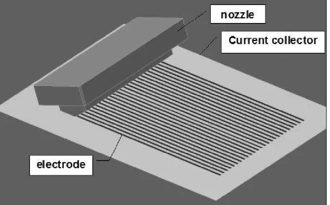
unit area was prepared. A schematic diagram of the printing apparatus for 3D micro
patterning (manufactured by Dainippon Screen Mfg.) is shown in Fig. 1. The composite
slurry was transferred from a supply unit to the nozzle unit. Then it was dispensed from
each nozzle at the same time on the aluminum current collector. Continuous application
is executed by moving a stage for lateral direction. The shape and size of the nozzle will
affect the cross sectional view as well as the size of the electrode. The cross sectional
view and the size are largely depend on a viscosity of the electrode slurry (over
3,000,000 cPs ) as well. After the application, the electrode was dried at 80 °C for 5
hours under vacuum condition.
18
Figure 1 A printing apparatus for 3D micro patterning.
19 2.2 Fabrication of conventional flat electrode
A conventional flat electrode was compared with the 3-D electrode. The
composite slurry for the flat electrode consisted of LTO, AB and PVdF in the weight
ratio of LTO:AB:PVdF = 8:1:1. This mixture was dispersed in NMP, and the weight
ratio of NMP in the slurry was approximately 65 %. The composite slurry was applied
onto the current collector by using a commercial applicator (YASUDA SEIKI
SEISAKUSHO, LTD.). The gap between applicator and the collector was adjusted to
control the battery capacity per unit area for 1 mA h cm-2. After application, the
electrode was dried at 80 °C for 5 hours under vacuum condition. The prepared flat
electrodes were then pressed at 30 MPa for 2 min before use.
2.3 Fabrication of a coin cell
Coin cells were fabricated, consisting of lithium metal as anode with the 3D
electrode or conventional flat electrode as cathode. A conventional porous
polypropylene film was used as a separator. The electrolyte was 1 mol dm-3LiPF6 in an
organic liquid mixture consisting of ethylene carbonate (EC) and ethyl methyl carbonate
(EMC) (1:1 in volume). Current collector was aluminum foil. The cells were assembled
in a glove box under argon atmosphere.
20
2.4 Evaluation of electrochemical performance of 3D electrode
Hereafter all the electrode potentials were referred to Li/Li+. Cyclic voltammetry
has been carried out for three times at a potential sweep rate of 10 mV min.-1 at 25 °C
by using a potentiostat (HZ-3000, Hokuto Denko). The potential range was set from 1 V
to 3 V. Charge-discharge behaviors of the cells were recorded with a charge-discharge
controller under constant current density (HJ-1001SD8, Hokuto Denko). The
charge-discharge voltage region was from 1.0 V to 3.0 V and current density was
changed from 0.1 to 5.0 C. The charge-discharge cycling performances were evaluated
by repeating the charging and discharging processes for two hundred times at 1 C rate.
The shape of the 3D electrode was observed with a laser-microscope (VK-9500,
Keyence). The cross sections of the 3D electrode were observed with a scanning
electron microscope (SEM) (JSM-6510, JEOL).
3. Results and discussion
3.1 Structure of 3D electrode
The observed image of 3D LTO cathode lines, which were fabricated by a micro
printing apparatus and dried at 80 °C for 5 hours under vacuum condition, is shown in
Fig.2. Line-formed electrodes with equal cross section were arranged at equal space
21
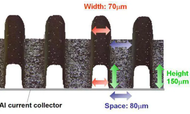
distance. The shape of the line-formed electrode is described as W 70 µm, H 150µm, S
80 µm (W: width of the line,H: height of the line ,S: width of the space between two
neighboring lines), and shows a repeated 3D patterning. Composite slurry including
active materials is not applied on the space area, and therefore aluminum current
electrode is exposed. Top of the line shows a round shape, and the dimensions and
proportion of the line are well defined by the nozzle used in electrode patterning. The
number and length of the line depend on the size of cell area. The aimed capacity per
unit area of the 3D LTO patterned cathode is 1 mA h cm-2as the same value with the
conventional flat cathode having the thickness of 70 µm. This 3D LTO cathode has
about 2.5 times surface area compared with the conventional flat cathode with the same
capacity.
22
Figure 2 Laser microscope image of 3D LTO cathode fabricated by the micro
patterning apparatus.
23
Figure 3 SEM images of the cross section of 3D LTO electrode observed at (a) ×
400, (b) × 1500 and (c) × 5000 magnifications.
24
Cross-sectional views of applied LTO electrode observed by SEM are shown in Fig. 3.
Active materials are well distributed in the matrix of electrode layer and dispersed
uniformly. It was also realized that PVdF binder was filled up uniformly. The dark
regions protruding at the top of line is the residue of glue used to prepare the
cross-sectional specimen.
Figure 4 shows the appearance of the 3D electrode on aluminum foil. The size of
applied area is 30 mm × 50 mm. There was not significant defect such as a shortage of
the line by application.
25
Figure 4 Photograph of the 3D LTO electrode prepared on an aluminum current
collector with an applied area of 30 mm × 50 mm.
26 3.2 Cyclic voltammogram
Figure 5 shows the cyclic voltammograms (CVs) of the cell consisting of 3D LTO
cathode with lithium metal as anode. The peak corresponding to lithium-ion
deintercalation (during charging process) was showed at 1.75 V which was slightly
more cathodic compared to the previously reported results [23, 24]. On the other hand,
the peak corresponding to intercalation (during discharging process) was seen at 1.40 V
which was slightly more anodic than those reported previously. The cell capacity was
estimated to be 160 mA h g-1by integrating the peak area. The same value of cell
capacity was obtained at the second and third cycles, suggesting that the cell with 3D
LTO cathode worked effectively as a rechargeable lithium-ion battery.
3.3 Galvanostatic charge and discharge test
The charge and discharge test has been carried out at constant currents ranging
from 0.2 C to 5 C rate to demonstrate the good rate capability of the 3D electrode cell
compared with the conventional flat electrode cell. Figure 6 shows the capacity
retentions at various C rates. All the retentions were calculated based on the capacity at
0.2 C of the third cycle.
27
Figure 5 Cyclic voltammograms of the half cell with 3D LTO cathode and lithium
metal anode at a potential sweep rate of 10 mV min-1at 25 °C.
28
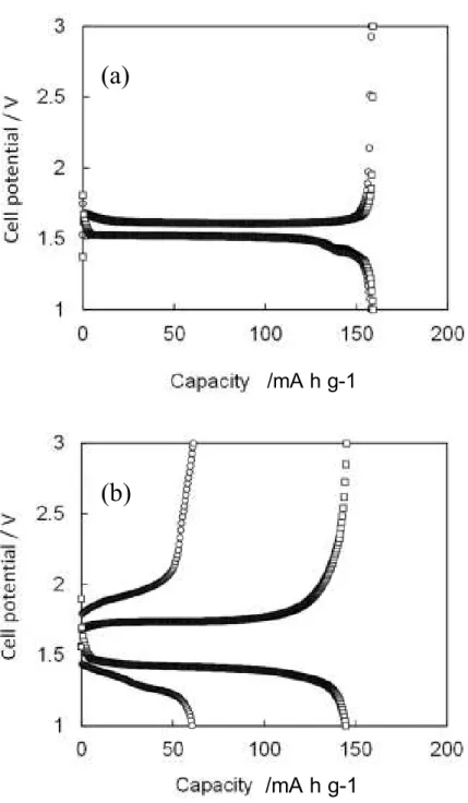
Figure 7 shows the charge and discharge curves at 1 C and 5 C, respectively. The
results of charge and discharge test for the 3D electrode cell showed that the capacity
retention rate at 5 C was 90 %. On the other hand, that of conventional flat electrode
was only 38 % at 5 C. These data suggest that the charge and discharge performance can
be largely improved by the 3D micro patterning of electrode. The capacity retention of
the flat electrode at 1 C was 97 %. The charge and discharge curves were approximately
equivalent to that of 3D electrode. However, the difference of potential plateaus at 5 C
between charging and discharging processes was larger than that of 3D electrode,
indicating that the resistance in the cell with flat electrode was high. Therefore, the
characteristics of charge and discharge at high C rate turned worse in the flat electrode.
It is probable that the resistance in the cell with 3D electrode is lower than that of the
flat electrode. These results suggest that the transport of lithium-ions in the cell with 3D
electrode is improved due to its electrode structure, resulting in the high capacity
retention at high C rate.
29
Figure 6 Capacity retentions on the cells with 3D patterned (□) and
conventional flat (○) LTO electrodes.
30
Figure 7 Galvanostatic charge-discharge curves of 3D patterned (□) and
conventional flat LTO electrodes (○) measured at (a) 1 C and (b) 5 C rates.
(a) (b)
/mA h g-1 /mA h g-1
/mA h g-1 /mA h g-1
(a)
(b)
31
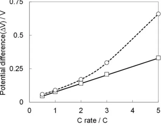
Figure 8 shows potential differences of the cells with 3D patterned cathode and
conventional flat cathode. The potential differences between 50%-charged and
50 %-discharged states for the capacities at each C rate were estimated by using the each
cell voltage value. The potential difference of the 3D patterned electrode increased
linearly. On the other hand, potential difference of the conventional flat electrode
increased rapidly at more than 2 C. This result shows that the conventional flat electrode
has a larger polarization resistance than that of 3D patterned electrode. The C rate of
horizontal axis indicates the current applied to the electrode, therefore the linear
relationship observed for 3D electrode suggests that the cell resistance is constant even
at high C rates. On the other hand, the resistance of conventional flat electrode increased
at more than 2 C. This difference is explained via the accessibility of lithium-ions
between the electrode and bulk electrolyte solution. For the case of conventional flat
electrode, lithium-ions diffuse to bulk of electrolyte solution from the electrode surface
faced to a counter electrode, and vice versa. Therefore, the rate performance of electrode
tends to be limited by lithium-ion diffusion, particularly in thick electrode and high rate
conditions. On the contrary, the 3D patterned electrode has high surface area that is
accessible for lithium-ions. As shown in Fig. 2, both sides of 3D electrode are open to
access to bulk electrolyte solution. Therefore, the electrode thickness practical for
32
lithium-ion diffusion can be considered to be the half of 70 µm. Consequently, the
resistance in the cell with 3D electrode was lower than that of the flat electrode. These
results suggest that the formation of 3D patterned electrode strongly improves the mass
transport in the cell, leading to excellent characteristics of charge and discharge at high
C rates.
33
Figure 8 Potential differences between 50 %-charged and 50 %-discharged states
in the charge/discharge curves obtained at various C rates on the 3D patterned (□)
and conventional flat (○) LTO electrodes.
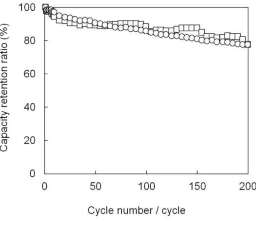
34 3.4 Charge-discharge cycle performance
Figure 9 shows cycle performances of the 3D patterned cathode and conventional
flat cathode at 1 C rate, respectively. The retention ratio of capacity for 3D patterned
electrode gradually decreased with the cycle number and was about 80 % after 200
charge-discharge cycles. This result suggests that the prepared 3D structure is
mechanically steady. The conventional flat electrode showed a similar cycle
performance as observed in Fig. 7 (a). As considering the result in Fig. 8, the electrode
reaction is expected to be hardly limited by the diffusion of lithium-ions at 1 C rate.
Therefore, the capacity fading observed in both cells is due to the deterioration of
composite electrode and is expected to be improved by further optimization of electrode
preparation. As shown in Fig. 6, the high rate performance without sacrificing the
energy density of batteries can be achieved by 3D patterned electrode, in which the
diffusion of lithium-ions through composite electrode and electrolyte take place more
smoothly by larger electrode surface area and shorter distance of lithium-ion diffusion
length than those in conventional flat electrode. Consequently, the 3D electrode with
high aspect ratio that stands on a current collector is a promising structure for high
energy density and high rate performance of lithium-ion batteries. Adopting the higher
aspect ratio and the smaller space of 3D electrode, the amount of active material in unit
35
area can be increased. A micro printing method combined with the manufacturing
process of electrode is a useful way to realize this kind of 3D structures.
36
Figure 9 Charge-discharge cycle performances of 3D patterned (□) and
conventional flat (○) LTO electrodes at 1 C rate.
37 4. Summary
3D patterned line electrode with 70 µm width and high aspect ratio of ~2 was
realized employing a micro printing method which was newly developed to fabricate 3D
integrated lithium-ion cells. The cyclic voltammogram of the half cell with 3D Li4Ti5O12
cathode and lithium metal anode indicated the peaks corresponding to the intercalation
and deintercalation of lithium-ions to and from Li4Ti5O12, reversibly. This result
suggests that 3D patterned electrode worked effectively. The capacity retention at 5 C
was 90% in the galvanostatic charge and discharge test. This capacity retention is 2.3
times larger than that obtained for the conventional flat electrode. It was also confirmed
that the 3D patterned electrode showed similar cycle performance to the conventional
flat electrode, suggesting that the prepared 3D pattern is mechanically steady. The
characteristics of the 3D structured electrode are as follows:
+ Large surface area of electrode films
+ Space between electrode patterns
+ Possible to enhance the diffusion of lithium-ions
+ Possible to increase the capacity with keeping rate performance as increasing the
aspect ratio
38 References
[1] K. Takeno, M. Ichimura, K. Takano and J. Yamaki, J. Power Sources, 142 (2005)
298.
[2] N. Sato, J. Power Sources, 99 (2001) 70.
[3] K. Kang, Y. S. Meng, J. Bréger, C. P. Grey, G. Ceder, Science, 311 (2006) 977.
[4] N. Li, C. R. Martin, B. Scrosati, Electrochem. Solid-State Lett., 3 (2000) 316.
[5] J. W. Fergus, J. Power Sources, 195 (2010) 939.
[6] J. Chen, M. J. Vacchio, S. Wang, N. Chernova, P. Y. Zavalij, M. S. Whittingham,
Solid State Ionics, 178 (2008) 1676.
[7] T. H. Cho, S. M. Park, M. Yoshio, T. Hirai, Y. Hideshima, J. Power Sources, 142
(2005)306.
[8] B. J. Landi, M. J. Ganter, C. D. Cress, R. A. DiLeo, R. P. Raffaelle, Energy Environ.
Sci., 2 (2009) 638.
[9] Y. S. Hu, R. D. Cakan, M. M. Titirici, J. O. Müller, R. Schlögl, M. Antonietti, J.
Maier,Angew. Chem. Int. Ed., 47 (2008) 1645.
[10] G. X. Wang, J. H. Ahn, J. Yao, S. Bewlay, H. K. Liu, Electrochem. Commun., 6
(2004)689.
[11] K. T. Lee, J. Cho, Nano Today, 6 (2011) 28.
39
[12] Y. Wang, G. Cao, Adv. Mater., 20 (2008) 2251.
[13] C. K. Chan, R. Ruffo, S. S. Hong, R. A. Huggins, Yi Cui, J. Power Sources, 189
(2009) 34.
[14] D. Deng, M. G. Kim, J. Y. Lee, J. Cho, Energy Environ. Sci., 2 (2009) 818.
[15] Zonghai Chen,a Yan Qin,a Khalil Amine*a and Y.-K. Sun, J. Mater. Chem., 20
(2010)7606.
[16] H. P. Zhang, L. C. Yang, L. J. Fu, Q. Cao, D. L. Sun, Y. P. Wu, R. Holze, J. Solid
State Electrochem., 13 (2009) 1521.
[17] K. Yoshima, H. Munakata, K. Kanamura, J. Power Sources, 208 (2012) 404.
[18] H. Munakata, H. Sugiura, K. Kanamura, Func. Mater. Lett., 2 (2009) 9.
[19] K. Dokko, J. Sugaya, H. Munakata, K. Kanamura, Chem. Lett., 34 (2005) 984.
[20] C. Lethien, M. Zegaoui, P. Roussel, P. Tilmant, N. Rolland, P.A. Rolland,
Microelectron. Eng., 88 (2011) 3172-3177.
[21] C. Wang, L. Taherabadi, G. Jia, M. Madou, Y. Yeh, B. Dunn, Electrochem.
Solid-State Lett., 7 (2004) A435-A438.
[22] J. W. Long, B. Dunn, D. R. Rolison, H. S. White, Chem. Rev., 104 (2004) 4463.
[23] Z. Yang, D. Choi, S. Kerisit, K. M. Rosso, D. Wang, J. Zhang, G. Graff, J. Liu, J.
Power Sources, 192 (2009) 588.
40
[24] T. Ohzuku, R. Yamato, T. Kawai, K. Ariyoshi, J. Solid State Electrochem., 12
(2008)979-985.
41
Chapter 3
Rapid Charge and Discharge Property of High
Capacity Lithium Ion Battery applying
Three-Dimensionally Patterned Electrode
42 1. Introduction
Lithium ion battery has higher energy density than other conventional
rechargeable batteries, and the amount of energy that can storage in the unit volume or
unit weight is large [1]. Hence recently, the lithium ion battery is used for electric
vehicles [2]. However, its performance is not still enough in both energy and
power densities. Therefore, development for aiming at higher energy density and higher
rate performance of lithium ion batteries are conducted intensively.
Lithium ion battery performance depends on the diffusion rate of lithium ion,
particularly in porous composite anode and cathode. High performance requires high
current of electrochemical reactions in batteries. In order to promote diffusion of the
lithium ion in the cell, it was focused on to increase the surface area of active materials
layer and to decrease the distance of lithium ion diffusion length between anode and
cathode. High energy density requires the higher mass per unit volume of active
material in the electrode. On the other hand, low diffusion resistance of lithium-ions in
the electrode is required to realize the high rates of charging and discharging. New
three-dimensional structured batteries were developed in order to resolve this limitation
problem on the structure of batteries [3]. We expected that three-dimensionally (3D)
integrated electrode structure is one of the effective solutions to realize the high rate
43
performance without sacrificing the energy density of batteries. A micro printing method
combined with the manufacturing process of electrode was directed aiming at a large
scale production of 3D structured electrodes for the upcoming demands in battery
development.
In the previous report,[1] the cyclic voltammogram of the half cell with 3D
Li4Ti5O12 cathode and lithium metal anode indicated a couple of reversible based on the
lithiation and delithiation of lithium ions to Li4Ti5O12 and from Li7Ti5O12, and which
suggests the 3D line patterned electrodes that were fabricated by the micro printing
apparatus work effectively. The capacity retention at 5 C was 90 % in the galvanostatic
charge and discharge test. These results showed the 2.3 times larger at 5 C for the 3D
patterned electrode than that obtained for the conventional flat electrode, and the
provability to enhance the diffusion of lithium ions.
In this study, cyclicvoltammetry was carried out to investigate the mechanism
realizing the high rates of charging and discharging. The interfacial resistance difference between the 3D cells and the conventional cell was analyzed by using AC impedance
measurement. In addition, the influences of basic specifications of electrode (the width
of space between two neighboring electrode lines, the height and the width of electrode)
on the charge-discharge characteristics were evaluated.
44 2. Experimental
2.1 Fabrication of 3D patterned and conventional flat electrode,
Electrochemical properties of the 3D patterned electrodes were evaluated by
using 2032 coin cells with lithium metal as an anode. Cathode consisted of 80 wt %
Li4Ti5O12(LTO ,ISHIHARA SANGYO KAISHA, LTD),10 wt % acetylene black(AB,
average diameter : 35 nm, DENKI KAGAKU KOGYO KABUSHIKI KAISHA)and 10
wt % poly(vinylidene difluoride)( PVdF ,KISHIDA CHEMICAL Co.,Ltd.)binder. The
mixture was dispersed into N-methylpyrrolidinone (NMP) to make the composite slurry.
The weight ratio of NMP in the slurry was about 50 wt % for 3D patterned electrode.
The slurry condition of high viscosity was selected for fabricating the 3D electrode by
using the micro printing system described in the former report [3]. By using these
materials, 1 mA h cm-2 of battery capacity per unit area was prepared. After application,
the electrode was dried at 80 oC for 5 hours under vacuum condition.
Figure 1 shows the cross sectional specifications (a) and the cross sectional SEM
image (b) of the 3D LTO cathode, which was used both for the experiment of
Cyclicvoltammetry and AC impedance measurements. These indicate the specifications
of 3D electrode fabricated by the micro patterning apparatus. The width of the space
between two neighboring electrode lines (S) is 80 µm. The height (H) and width (W) of
45
the electrode line are 150 µm and 70 µm, respectively.
A conventional flat electrode was compared with the 3D electrode. The composite
slurry for the flat electrode consisted of LTO, AB and PVdF in the weight ratio of
LTO:AB:PVdF=8:1:1 same as the 3D electrode. This mixture was dispersed in NMP ,
and the weight ratio of NMP in the slurry was approximately 65 %. The composite
slurry was applied onto a aluminum current collector by using a commercial applicator
(YASUDA SEIKI SEISAKUSHO,LTD.). The gap between applicator and the current
collector was adjusted to control the battery capacity per unit area for 1mAh/cm2 which
is as same as the 3D electrode. After application, the electrode was dried at 80 oC for 5
hours under vacuum condition both for 3D and flat electrode. Only flat electrode films
were then pressed at 30 MPa for 2 min before use. On the contrary, 3D electrode was
not pressed to maintain this structure.
46 (a) Cross section
(b) Cross sectional SEM image
Figure 1 Cross sectional specifications (a) and SEM image (b) of LTO 3D cathode
on aluminum current collector fabricated by the micro patterning apparatus.
H 150 um
W 70 µm
S 80 µm H 150 um
W 70 µm
S 80 µm
47 2.2 Fabrication of a coin cell
Coin cells were fabricated, consisting of lithium metal as anode with the 3D
electrode or conventional flat electrode as cathode. A conventional porous
polypropylene film was used as a separator. The electrolyte was 1 mol dm-3 LiPF6 in
an organic liquid mixture consisting of ethylene carbonate (EC) and ethyl methyl
carbonate (EMC) (1:1 volume). Current collector was aluminum foil. The cells were
assembled in a glove box under argon atmosphere.
2.3 Evaluation of electrochemical performance of 3D electrode
Hereafter all the electrode potentials were referred to Li/Li+. Cyclicvoltammetry
has been carried out respectively at a potential sweep rate of 20, 50 and 100 mV min-1 at
25 oC by using a potentiostat (HZ-3000,Hokuto Denko). Charge-discharge behaviors
of the cells were recorded with a charge-discharge controller under constant current
density (HJ-1001SD8, Hokuto Denko). The charge-discharge voltage region was from
1.0 V to 3.0 V and current density was 0.2 C.
The impedance measurement was performed at every 20 % SOC at 25 oC using a
potentiostat (SI1287, Solartron,) and a frequency response analyzer ( 1252A, Solartron).
The cell was discharged at the rate of 0.2 C starting from SOC 100 % to 0 %.
48
The frequency range was 1MHz-1Hz, and the amplitude of the voltage was 5 mV.
The shape of the 3D electrode was observed with a laser-microscope (VK-9500,
Keyence).
3. Results and Discussion
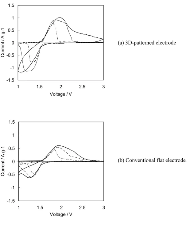
3.1 Cyclicvoltammograms
Cyclicvoltammetry at each scan rate for 3D patterned electrode and conventional
flat electrode were carried out. Fig. 2 shows the cyclic voltammograms(CVs) of the
third cycle for the cell consisting of the 3D LTO cathode (a) and the conventional flat
LTO cathode (b) with lithium metal as the anode. The 3D electrode shows the sharp
peak and the flat electrode indicates broad ones. And current value of the 3D electrode
after 2 V for scan rate of 20 mV min.-1 and after 2.4 V for scan rate of 50 mV min.-1
shows nearly 0 A. On the other hand, charge current for the flat electrode still flows a
little in the same conditions. This result shows 3D electrode has a lower overpotential
for charge and discharge reactions than that of flat one.
Table 1 shows the cell capacity integrating by CV current peak values indicated
by Fig.2, and that both type electrode can be fully charged at 20 mV min.-1, which is the
relatively slow scan rate condition. However, the flat electrode can not be fully charged
49
at the 50 mV min.-1 condition. 3D electrode can be fully charged at the 50 mV min.-1
condition. From these results, it can be found that lithium ion diffusion rate in the cell of
3D electrode is faster than that of flat electrode, and rapid charge and discharge were
realized.
50 -1.5
-1 -0.5 0 0.5 1 1.5
1 1.5 2 2.5 3
Voltage / V
Current / A g-1
-1.5 -1 -0.5 0 0.5 1 1.5
1 1.5 2 2.5 3
Voltage / V
Current / A g-1
(a) 3D-patterned electrode
Figure 2 Cyclic voltammogram of each scan rate for the cell, (a) 3D-patterned and
(b) conventional flat cathode with lithium metal as anode. 100 mV min-1 (solid
line), 50 mV min-1 (dashed line), 20 mV min-1 (dotted line).
(b) Conventional flat electrode
51
20 mV min-1 50 mV min-1 100 mV min-1
Charge 158.0 154.9 121.8
Discharge 157.8 154.8 113.0
Charge 154.9 127.9 116.7
Discharge 154.8 110.7 93.0
(unit:mA h g-1)
Electrode type scan rate mV min-1
3D-Patterned Conventional flat
Table 1 Integrated capacity of CV for the cell at conventional flat LTO and
3D patterned LTO cathode with lithium metal as the anode.
52 3.2 AC impedance measurements
Figure 3 shows the galvanostatic charge and discharge curves at 0.2 C rate for the
cell with conventional flat LTO (a) and 3D-patterned LTO (b) cathode. Charge and
discharge were stopped at every 20 % SOC, and the electrochemical AC impedance
measurements were fulfilled. The ohmic resistance (Rs) and charge-transfer resistance
(Rct) were calculated by using the Nyquist plots obtained from the impedance
measurements. Rs was assigned to the intercept of the semicircle at Z’ abscissa in the
low frequency region, and Rct was calculated from the diameter of semicircle. This
calculation method is shown in Fig.4 and the results of Rct are shown in Fig.5. The
average Rs values of the 3D and the flat electrode were 6.98 Ω and 7.78 Ω, respectively,
and the 3D electrode has a relatively small value. Rct value during charging is a little
smaller than that of discharging. Rct value of 3D electrode is smaller than that of the
flat one in the condition of SOC 0 and 20 %. The reason for this difference is unclear,
but there is only a slight difference of resistance between the both type electrodes.
Therefore almost equal resistance values were obtained because the same active
materials were used for both cases. These results do not depend on the electrode
structure of the 3D and the conventional flat.
53
(a) conventional flat electrode
(b) 3D patterned electrode
Figure 3 Galvanostatic charge-discharge curves of 0.2C rate for the
cell, (a) conventional flat electrode and (b) 3D patterned cathode
combined with lithium metal as anode.
1 1.5 2 2.5 3
0 20 40 60 80 100 120 140 160
Capacity mAh/g
V vs.Li/Li+
1 1.2
1.4 1.6
1.8 2
x in Lix[Li1/3Ti5/3]O4
2 1 3
5 4
6 7 8 9
10
SOC100 SOC0%
Charge
Discharge
/mA h g-1
SOC 100%
SOC 0%
1 1.5 2 2.5 3
0 20 40 60 80 100 120 140 160
Capacity mAh/g
V vs.Li/Li+
1 1.2
1.4 1.6
1.8 2
x in Lix[Li1/3Ti5/3]O4
2 1 3
5 4
6 7 8 9
10
SOC100 SOC0%
Charge
Discharge
/mA h g-1 1
1.5 2 2.5 3
0 20 40 60 80 100 120 140 160
Capacity mAh/g
V vs.Li/Li+
1 1.2
1.4 1.6
1.8 2
x in Lix[Li1/3Ti5/3]O4
2 1 3
5 4
6 7 8 9
10
SOC100 SOC0%
Charge
Discharge
/mA h g-1
SOC 100%
SOC 0%
1 1.5 2 2.5 3
0 20 40 60 80 100 120 140 160
Capacity mAh/g
potential V vs.Li/Li+
1 1.2
1.4 1.6
1.8 2
x in Lix[Li1/3Ti5/3]O4
2 1 3
5 4
6 7
8 9 10
SOC100 SOC0%
Charge
Discharge
/mA h g-1
SOC 100%
SOC 0%
1 1.5 2 2.5 3
0 20 40 60 80 100 120 140 160
Capacity mAh/g
potential V vs.Li/Li+
1 1.2
1.4 1.6
1.8 2
x in Lix[Li1/3Ti5/3]O4
2 1 3
5 4
6 7
8 9 10
SOC100 SOC0%
Charge
Discharge
/mA h g-1
1 1.5 2 2.5 3
0 20 40 60 80 100 120 140 160
Capacity mAh/g
potential V vs.Li/Li+
1 1.2
1.4 1.6
1.8 2
x in Lix[Li1/3Ti5/3]O4
2 1 3
5 4
6 7
8 9 10
SOC100 SOC0%
Charge
Discharge
/mA h g-1
SOC 100%
SOC 0%
54
-5
0
5 10
Z' / Ω
Z " / Ω
○1M~10kHz
●10k~1kHz □1k~1Hz
Rs Rct
Figure 4 Schematic showing Rs and Rct in nyquist plot.
1MHz-10kHz (○), 10kHz-1kHz (●), 1kHz-1Hz (□).
55
1.00 10.00 100.00
0 20 40 60 80 100
SOC(%)
R c t (Ω )
Figure 5 Rct as a function of state of charge (SOC) : dashed line;
discharge-conventional flat electrode, dotted line; charge-conventional flat
electrode, chain line; discharge-3D patterned electrode, solid line;
charge-3D patterned electrode
56
3.3 Influence of the specifications of 3D electrode on battery properties
Basic specifications of 3D electrode on the charge and discharge characteristics
were evaluated. The basic structure of 3D electrode is the same as showed in Fig.1.
The width of space between two neighboring LTO electrode lines (S) were selected 100,
50, 25 and 15 µm. The width of the LTO electrode line (W) was between 95 and 100
µm. The height of the LTO electrode line (H) was 65 µm. The charge and discharge test
were carried out at constant currents ranging from 0.1 to 10 C. Fig. 6 shows the
capacity retentions at various C rates for the cells with 3D-patterned LTO
cathode/lithium anode. Narrow width of the space between two neighboring LTO
cathode does not affect the capacity retention level except the case of 15 and 25 µm
space at 5 and 10 C.
Figure 7 shows the capacity per unit area on C rate for the cells with 3D-patterned
LTO cathode/lithium anode by changing the width of space between two neighboring
LTO cathode lines. This data suggests that capacity can be increased by reducing space.
57 0
20 40 60 80 100
0.1 1.0 10.0
C rate/C
Capacity retention ratios/%
Figure 6 Capacity retention ratios as a function of C rate for the cells with
3D-patterned LTO cathode/lithium metal anode by changing width of space
between two neighboring electrode lines. 100 µm (△), 50 µm (□), 25 µm (○),
15 µm (◇)
58 0.0
0.2 0.4 0.6 0.8 1.0 1.2
0.1 1.0 10.0
C rate/C
Capacity per unit area/mAh/cm2
Figure 7 Dependency of capacity per unit area on C rate for the cells with
3D-patterned LTO cathode/lithium anode by changing the width of space between
two neighboring electrode lines. 100 µm (△), 50 µm (□), 25 µm (○), 15 µm (◇)
59
Next, the influence of the 3D electrode height was evaluated. The height of 3D
LTO cathode line was selected 50, 70 and 90 µm. The width of the space between two
neighboring LTO electrode lines was 100µm. The width of the LTO electrode line was
between 95 and 100 µm. The charge and discharge test were carried out at the same
conditions as previous one. Fig. 8 shows the capacity retentions at various C rates for
the cells with 3D patterned LTO cathode/lithium anode. Fig. 9 shows the capacity per
unit area on C rate for the same cells. These results show that the increase of the
electrode height did not affect the capacity retentions at every C rate, and capacity per
unit area could be improved at the same time.
60
0 20 40 60 80 100
0.1 1.0 10.0
C rate / C
Capacity retention ratios / %
Figure 8 Capacity retentions ratios as a function of C rate for the cells
with 3D-patterned LTO cathode/lithium metal anode. The height of
cathode (H) are 50 (○), 70 (□) and 90 (△) µm.
61 0.00
0.25 0.50 0.75 1.00
0.1 1.0 10.0
C rate / C
Capacity per unit area / mAh cm-2
Figure 9 Capacity per unit area as a function of C rate for the cells with
3D-patterned cathode/lithium anode. The height of cathode (H) are 50 (○),
70 (□) and 90 (△) µm.
62
For further investigation of the height of 3D electrode, internal resistance at the
time of charge (Rc) and discharge (Rd) were estimated by AC impedance method for the
3D electrodes with 50, 70 and 90 µm in height as showed in figure 10. All the 3D
electrodes showed about 15 and 30 Ω g-1 as Rc and Rd, respectively. The mass of
active materials per unit area was controlled to be equal, therefore the internal resistance
of the electrode is expressed as Ω g-1. This result clearly suggests that both Rc and Rd
are hardly affected by the height of 3D electrode, and the lithium ion diffusion from the
lateral direction is dominant in the 3D electrode.
63
Figure 10 Internal resistance of 3D-patterned LTO electrode at the
time of charge (○) and discharge (●).
0 10 20 30 40 50
30 50 70 90 110
Height / µm
R e s is ta n c e /Ω g -1
64
The influence of the 3D electrode width was also evaluated. The width of LTO
cathode line (W) was selected 70 and 100 µm. The height of the LTO cathode (H) was
selected as the capacity (cross section) became approximately equal. H are 150 µm for
W 70 µm, and 100 µm for W 100 µm, respectively. The width of space between two
neighboring electrode was 110 µm. The charge and discharge test were carried out at the
same conditions as previous one. Fig.11 shows the capacity retentions on C rate for the
cells with the width of 70 and 100 µm 3D-patterned LTO cathode/lithium anode. For
the case of narrower 70 µm electrode, higher capacity was obtained at over 10 C
conditions.
Figure 12 shows the Galvanostatic charge-discharge curves for the same cells as in
Fig.11. The narrower 70 µm electrode cell kept the higher capacity. Therefore, the
narrower width of electrode should be suited for enhancement of lithium ion diffusion in
the electrode.
65
0 20 40 60 80 100
0.1 1 10 100
C rate/C
C ap ac it y re te n ti o n r at io s/ %
Figure 11 Capacity retentions ratios as a function of C rate for different pattern
size: width 70um and height 150 µm (●), width 100 µm and height 100 µm (□).
66
Figure 12 Galvanostatic charge-discharge curves of 3D-patterned LTO
cathode with different pattern size: width 70 µm and height 150 µm (●),
width 100 µm and height 100 µm (□).