著者名(日) 青木 立, 川田 誠一
雑誌名 東京都立産業技術高等専門学校研究紀要
巻 6
ページ 19‑23
発行年 2012‑03
URL http://id.nii.ac.jp/1282/00000129/
Creative Commons : 表示 ‑ 非営利 ‑ 改変禁止 http://creativecommons.org/licenses/by‑nc‑nd/3.0/deed.ja
+
+ y (k)
Noise
r (k)
1 A (q
−−−−1)
e (k)
B (q
−−−−1) A (q
−−−−1)
y ( k) Noise
1 A (q
−−−−1)
e ( k )
システム同定アルゴリズムに関するロバスト性の検証
| 逐次最小二乗法に関する検証 |
The Verification of The Robustness of The System Identification Algorithm
— The Verification on The Recursive Least Squares Method —
青 木 立1), 川 田 誠 一2)
Tatsu Aoki
1),Seiichi Kawata
2)Abstract:The mathematical model of a plant is required in order to design a control system. Especially, the system param- eters must be estimated in real-time to keep the desired control performance in the case of the plant parameter variations.
Though the number of identification method are proposed, they need much amount of calculation and the calculations methods are based on double precision floating point arithmetic. Then, it is difficult for the fixed point microprocessor whose word length is short to calculate the algorithm precisely within sampling interval. Thus, the aim of this research is to propose a system identification method for the embedded mechatronic control systems. As a first step of this research, system parameter estimation on 2nd-order system is considered. ARX model is adopted as a system model and system parameters are estimated by the recursive least squares with forgetting factor. As a disturbance, noise is injected in the plant output, dead zone and offset are injected in the plant input to verify the robustness of the algorithm. Simulation results show that the measurement noise on the plant output gives most large effect at the parameter estimation error.
Keywords: System identification, ARX model, Digital controller, Microprocessor control
1. はじめに
組込み型メカトロニクスシステムでは省エネルギー化,
省スペース化,低コスト化などから8ビットなど語長が短 い固定小数点マイクロプロセッサが用いられる.語長が短 い固定小数点演算では,制御アルゴリズム係数の表現誤差 や狭いダイナミックレンジのため演算精度が低くなる.そ の結果,仕様を満たす制御性能の実現が困難なだけではな く,制御系が不安定になる.この数値的不安定性は,デル タオペレーション手法により大幅に改善される[1-6].筆者 はデルタオペレータに基づいた手法を実用化することによ り,制御アルゴリズムの実装手法及びモデルマッチングに 基づいた2自由度コントローラの設計法を確立した[7-16]. ところで,制御系を設計するためには制御対象に関する 数式モデルが必要となる.制御対象の特性が時間的に大き く変化する場合には,所定の制御性能を維持するためオン ラインでのシステムのモデリングが必要になる.このた め,従来から種々の手法が提案されている[17-18].しか し,従来手法は演算量が多く,オフラインかつ倍精度浮動 小数点演算を前提にしている.このため,語長が短い固定 小数点マイクロプロセッサでは演算精度の確保やサンプリ ング間隔内での演算処理が困難であり,従来手法を組込み 型メカトロニックシステムに直ちに応用できない.
1)東京都立産業技術高等専門学校 ものづくり工学科,電気電子工学コース 2)産業技術大学院大学
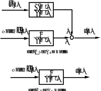
Fig. 1 The ARX model
Fig. 2 The AR model
本研究では演算精度が低く,演算速度が遅い固定小数点 マイクロプロセッサを用いた場合でも,オンラインでパラ メータ推定が可能な手法の開発を目的とする.研究の第 1段階として,図1に示すARXモデルに関して逐次最小二 乗法によりパラメータを推定する.なお,ARXモデルは 図2に示すARモデルに外部入力を加えたモデルである.
東京都立産業技術高等専門学校 研究紀要 第6号
Plant –
Zero-order Zero-order hold
hold
A
(s)
+Model
B
(q
−−−−1)
A
(q
−−−−1)
Plant –
Zero-order Zero-order hold
hold
B
(s)
A(s)
y(k)
r
(k)Model
B
(q
−−−−1)
A
(q
−−−−1)
+ +
Offset
Plant –
Zero-order Zero-order hold
hold
B
(s)
A(s)
y(k)
r
(k)Model
B
(q
−−−−1)
A
(q
−−−−1)
Dead zone ここで,
A(q−1) = 1+a1q−1+a2q−2+· · ·+anq−n B(q−1) = b0+b1q−1+b2q−2+· · ·+bnq−n とする.推定パラメータを
Θ(k) = [aˆ 1(k)a2(k)a3(k)· · · b0(k)b1(k)b2(k)· · ·] と定義すると,プラントの出力y(k)と推定パラメータに基 づいた予測値ˆy(k)は,それぞれ,
y(k) = ΨT(k) ˆΘ(k) +e(k) (2) ˆ
y(k) = ΨT(k) ˆΘ(k−1) (3) になる.これらの差を∆y(i),重み,すなわち,忘却係数をλと すると,重み付き逐次最小二乗法は,誤差
k i=1
λk−i∆y2(i)が 最小になるように逐次パラメータを推定する.
Θ(k) = ˆˆ Θ(k−1) +K(k) (y(k)−ˆy(k)) (4) ここで,
K(k) =P(k)Ψ(k) とすると,K(k)は以下により求まる.
P(k) = P(k−1)
λ+ ΨT(k)P(k−1)Ψ(k) (5)
P(k) = 1 λ
P(k−1)−P(k−1)Ψ(k)ΨT(k)P(k−1) λ+ ΨT(k)P(k−1)Ψ(k)
(6) 3. システム同定結果
3.1 連続時間系のモデル
ここでは以下に示す2次系について考える.
H2(s) = ω2n
s2+2ζωns+ωn2 (7) 連続時間系となるプラントから0次ホールドにより得られ たデータに基づいてパラメータを推定する.外乱として 図3に示す観測ノイズ,図4に示すアクチュエータ駆動アン プのオフセット,図5に示す制御対象の摩擦などによる不 感帯の3種類を考える.これらの外乱の下で,パラメータ 推定値が式(7)を離散化して得られるパラメータ
H2(q) = b1q+b2 q2+a1q+a2
(8) に収束するかどうかを検証する.
Fig. 3 The parameter estimation considering the measurement noise
Fig. 4 The parameter estimation considering the offset of the power amplifier
Fig. 5 The parameter estimation considering dead zone of the plant
3.2 シミュレーション結果
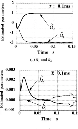
シミュレーションには,Matlab/Simulink及びSystem identification Toolboxを用い,プラントはSimulink上で 連続時間系のブロックとして表現した.なお,ζは0.7, ωnは100rad/sに設定した.入力信号は振幅が1,周波数 が1Hzの正弦波を用いた.さらに,オフセット及び不感帯 は両者とも0.1に,λは0.98に設定した.図6から図9に入 出力データをサンプリング周期T0.1msで取得した場合,
図10から図13に1msで取得した場合の推定結果を示す.
0 0.05 0.1 0.15 -2
-1 0 1 2
Time s
Estimated parameters
ˆ a
1a ˆ
2: 0.1ms
T0 0.05 0.1 0.15
-0.001 0.000 0.001 0.002 0.003
Time s
Estimated parameters
: 0.1ms
Tb ˆ
1b ˆ
20 0.05 0.1 0.15
-2 -1 0 1 2
Time s
Estimated parameters
ˆ a
1ˆ a
2: 0.1ms
T0 0.05 0.1 0.15
-0.003 -0.002 -0.001 0.000 0.001 0.002 0.003
Time s
Estimated parameters
: 0.1ms
Tb ˆ
1b ˆ
20 0.05 0.1 0.15
-2 -1 0 1 2
Time s
Estimated parameters
ˆ a
1a ˆ
2: 0.1ms
T0 0.05 0.1 0.15
-0.001 0.000 0.001 0.002 0.003
Time s
Estimated parameters
: 0.1ms
Tb ˆ
1b ˆ
20 0.05 0.1 0.15
-2 -1 0 1 2
Time s
Estimated parameters
ˆ a
1ˆ a
2: 0.1ms
T0 0.05 0.1 0.15
-0.10 -0.05 0.00 0.05 0.10
Time s
Estimated parameters
:0.1ms
Tb ˆ
1b ˆ
2(a)ˆa1andˆa2
(b)ˆb1andˆb2
Fig. 6 Parameter estimation without disturbance
(a)ˆa1andˆa2
(b)ˆb1andˆb2
Fig. 7 Parameter estimation under dead zone
(a)ˆa1andˆa2
(b)ˆb1andˆb2
Fig. 8 Parameter estimation under offset
(a)ˆa1andˆa2
(b)ˆb1andˆb2
Fig. 9 Parameter estimation under white noise
0 0.05 0.1 0.15 -2
-1
Time s
Estimated parameters
ˆ a
1ˆ
a
20 0.05 0.1 0.15
0.00 0.01 0.02
Time s
Estimated parameters
: 1ms
Tb ˆ
1b ˆ
20 0.05 0.1 0.15
-2 -1 0 1 2
Time s
Estimated parameters
ˆ a
1ˆ a
2: 1ms
T0 0.05 0.1 0.15
0.00 0.01 0.02
Time s
Estimated parameters
: 1ms
Tb ˆ
1b ˆ
20 0.05 0.1 0.15
-2 -1
Time s
Estimated parameters
ˆ a
1a ˆ
20 0.05 0.1 0.15
0.000 0.001 0.002 0.003
Time s
Estimated parameters
: 1ms
Tb ˆ
1b ˆ
20 0.05 0.1 0.15
-2 -1 0 1 2
Time s
Estimated parameters
ˆ a
1ˆ a
2: 1ms
T0 0.05 0.1 0.15
0.00 0.01 0.02
Time s
Estimated parameters
: 1ms
Tb ˆ
1b ˆ
2(a)ˆa1andˆa2
(b)ˆb1andˆb2
Fig. 10 Parameter estimation without disturbance
(a)ˆa1andˆa2
(b)ˆb1andˆb2
Fig. 11 Parameter estimation under dead zone
(a)ˆa1andˆa2
(b)ˆb1andˆb2
Fig. 12 Parameter estimation under offset
(a)ˆa1andˆa2
(b)ˆb1andˆb2
Fig. 13 Parameter estimation under white noise
さらに,観測ノイズはホワイトノイズとし,パワーは1×10⁻⁶に 設定した.このとき,式(8)に示すプラントパラメータは
• T:0.1ms
{a1 a2} = { −1.9860 0.9861}
{b1 b2} = {4.9767×10⁻⁵ 4.9535×10⁻⁵}
• T:1ms
{a1 a2} = { −1.8600 0.8600}
{b1 b2} = {4.7707×10⁻³ 4.7707×10⁻³} となる.シミュレーション結果より,パラメータ推定に関 する外乱の影響は以下になる.
• 不感帯
極に関しては両サンプリング周期とも推定誤差へ の影響が小さい.零点に関してはサンプリング周期
が0.1msのとき,誤差が大きくなる.
• パワーアンプのオフセット
極に関しては両サンプリング周期とも推定誤差への 影響が小さい.零点に関しても同様である.
• 観測ノイズ
極,零点の両方とも推定誤差への影響が大きい.サ ンプリング周期が0.1msのとき,誤差が大きくなる.
4. 今後の展望
従来手法は外乱に弱く,また,推定値にサンプリング周 期Tが含まれるため,サンプリング周期Tにより推定値が変 化する.高速サンプリング時には推定誤差が大きくなる.
一方,従来手法は確率,統計理論に基づいて考案されて おり,制御についてはほとんど考慮されていない.
本研究では制御,組込み型メカトロニクスシステムに とって有用な手法について検討する.モデル規範型制御 や単純適応制御とデルタオペレーションを融合した手法 を既に提案しており[19,20],これらの手法の実用化を目指す.
5. 結 論
従来手法の課題を抽出するため,2次系に関して逐 次 最 小 二 乗 法 に よ り パ ラ メ ー タ を 推 定 し た . 外 乱 と し て メ カ ニ ズ ム の 不 感 帯 , パ ワ ー ア ン プ の オ フ セ ッ ト,観測ノイズの3種類を考えた.シミュレーション の結果,観測ノイズが最も推定誤差に影響することがわかった.
6. 謝 辞
本研究は平成23年度より設置された公立大学法人 首 都大学東京 大学・高専連携事業基金による共同研究、
「組込み型メカトロニックシステムの実用化に関する研究
(研究期間3年)」の助成によって行われた.
7. 参 考 文 献
[1] R. M. Goodall: High-speed digital controllers using an 8bit microprocessor, Software & Microsystems,4, 5/6, pp.246- 250, 1985
[2] R. H. Middleton and G. C. Goodwin: Improved finite word length characteristics in digital control using delta opera- tors, IEEE Trans. on Automatic Control,31, 11, pp.1015- 1021, 1986
[3] R. M. Goodall, “Minimisation of computation for digital controllers, Trans. Inst MC,11, 5, pp.218-224, 1989 [4] R. H. Middleton and G. C. Goodwin: Digital Estimation
and Control -A Unified Approach-, New Jersey:Prentice- Hall, 1990
[5] G. C. Goodwin and R. H. Middleton and H. V. Poor: High- Speed Digital Signal Processing and Control, Proc. The IEEE,80, 2, pp.240-259, 1992
[6] 金井喜美雄,堀 憲之:ディジタル制御システム入門
—デルタオペレータの適用—,槙書店, 1992
[7] T. Aoki: Implementation of Modified Delta Form for Microprocessors using Fixed-Point Arithmetic, Proc. of American Control Conference, pp.4056-4060, 1999 [8] 青木 立:固定小数点マイクロプロセッサに適した制
御アルゴリズムの実装方法(第1報)—変数変調デル タオペレーションのPID制御系への適用と実機による 検証—,精密工学会誌,71, 3, pp.394-398, 2005 [9] 青木 立:修正デルタ形式に基づいたオブザーバの実
機による検証—固定小数点マイクロプロセッサに適 したデルタ形式—,東京都立産業技術高等専門学校研 究紀要, 1, pp.15-20, 2007
[10] T. Aoki: A Reduction of Round-off Noise Based on the Modified Delta Form for Fixed-Point Arithmetic, Proc.
19th Int. Conf. on Noise and Fluctuation, pp.724-727, 2007 [11] T. Aoki: Implementation of Fixed-Point Control Algo- rithms Based on the Modified Delta Operator and Form for Intelligent Systems, J. of Advanced Computational Intelli- gence and Intelligent Informatics,11, 6, pp.709-714, 2007 [12] T. Aoki: A Robot Control Based on the Modified Delta Form, Proc. of The 17th CISM-IFToMM Symposium on Robot Design, Dynamics, and Control(Romansy2008), pp.190-197, 2008
[13] T. Aoki:Micromechatronics Control Methodology Based on The Modified Delta Operator and Form using Bang- Bang Control, Proc. of the 2009 JSME-IIP/ASME-ISPS Joint Conference on Micromechatronics for Information and Precision Equipment, pp.379-380, 2009
[14] 青木 立:固定小数点マイクロプロセッサに適した制 御アルゴリズムの実装方法(第2報)―修正変数変調 法の提案―,精密工学会誌75, 7, pp.876-881, 2009 [15] T. Aoki, Implementation of a Fixed-Point 2 DOF Con-
troller Based on the Modified Delta Form for Embed- ded Mechatronic Systems, Proc. of The 2010 International Symposium on Intelligent Systems (iFAN 2010), Paper No.537 6 pages, 2010
[16] T. Aoki, Control Law Design Based on the Polyno- mial Method for Active Damping of Oscillatory Modes- The Application of the Delta Operator to the Polynomial Method -, Journal of System Design and Dynamics(Special issue of MOVIC2010)5, 5, pp.1045-1060, 2011
[17] M. Gevers, A Personal View of the Development of System Identification,IEEE Control System Magazine,26, 6, pp.
93-105, 2006
[18] L. Ljung, Perspectives on System Identification, Proc. of IFAC World Congres 2008,27,15, pp.15736-15747, 2008 [19] T. Aoki and S. Kawata, On-Line Physical Parameter
Estimation by Using Model Reference AdaptiveControl Method based on the Modified Delta Form, Proc. of SICE Annual Conference 2011, pp.1897-1902, 2011
[20] 青木立,川田誠一,単純適応制御に基づいたシステムモデ リング–デルタ形式による物理量のリアルタイム推定–
第54回自動制御連合講演会予稿集(SICE), pp.351-354, 2011