親水・撥水複合面上のプール沸騰に及ぼす溶存空気 および系圧力の影響
山田, 将之
https://doi.org/10.15017/1931912
出版情報:Kyushu University, 2017, 博士(工学), 課程博士 バージョン:
権利関係:
Effect of D issolved A ir and System P ressure on
Pool Boiling from Biphilic Surfaces
M asayuki Y am ada
i
Table of Contents
List of Figures iv
List of Tables xi
Nomenclature xii
Chapter 1 Introduction 1
1.1 Background 1
1.2 Basics of boiling phenomenon 4
1.2.1 Boiling curve 4
1.2.2 Boiling incipience 6
1.2.3 Bubble growth and departure 8
1.2.4 Heat transfer mechanism of nucleate boiling 10
1.2.5 Factors affecting pool boiling 11
1.3 Surface wettability 13
1.4 Literature survey 15
1.4.1 Improvement of boiling characteristics through wettability modification 16 1.4.2 Effect of dissolved air on boiling characteristics 23 1.4.3 Boiling characteristics under sub-atmospheric conditions 25
1.5 Research objectives 27
1.6 Thesis organization 28
Chapter 2 Fabrication of heating surfaces 30
2.1 Fabricating methods 30
2.1.1 Mirror-finished copper surface 30
ii
2.1.2 TiO2 sputtering 31
2.1.3 PTFE spray coating 32
2.1.4 P-HNT coating 33
2.1.5 Ni/TFEO electroplating 34
2.2 Contact angle measurement 36
Chapter 3 Effect of dissolved air on subcooled boiling 37
3.1 Experimental apparatus 37
3.1.1 Open type apparatus 37
3.1.2 Closed type apparatus 39
3.1.3 Heat transfer block 40
3.2 Experimental procedures and data reduction 41
3.2.1 Degassing 41
3.2.2 Boiling heat transfer experiment 45
3.2.3 Single bubble experiment 46
3.3 Boiling heat transfer characteristics 47
3.3.1 Mirror-finished copper surface 47
3.3.2 Biphilic surface 51
3.4 Single bubble behavior 55
3.4.1 Bubble behavior and bubble departure diameter and frequency 55
3.4.2 Temperature inside bubble 60
3.5 Numerical simulation of single bubble behavior 64
3.6 Heat transfer mechanisms 68
3.7 Summary 70
Chapter 4 Effect of system pressure 72
iii
4.1 Experimental apparatus and heating surfaces 72
4.2 Experimental procedures and data reduction 73
4.2.1 Boiling heat transfer experiment 73
4.2.2 Single bubble experiment 75
4.3 Boiling heat transfer characteristics 75
4.3.1 Heat transfer enhancement with a biphilic surface 76
4.3.2 Effects of spot diameter and pitch 83
4.3.3 Transition to intermittent boiling on a biphilic surface 88
4.3.4 Comparison with previous studies 94
4.4 Single bubble behavior 95
4.4.1 Bubble behavior and TPCL motion 95
4.4.2 Bubble departure diameter 98
4.4.3 Bubble growth rate 101
4.5 Summary 103
Chapter 5 Conclusions 106
Acknowledgement 110
References 111
Chapter A Appendix 126
A-1 Uncertainty analysis 126
A-2 Contact angle measurement 127
A-3 Gas solubility 128
A-4 Detail of numerical simulation 129
iv
List of Figures
Figure 1.1 A typical boiling curve obtained for upward facing surfaces or horizontal wires with controlled heat flux. Schematics of boiling modes are displayed above the graph. 5 Figure 1.2 Condition for heterogeneous nucleation from a conical cavity with a radius of
rc. 8
Figure 1.3 Schematic of bubble cycle. 9
Figure 1.4 Heat transfer mechanism during (a) bubble growth and (b) departure
processes. 10
Figure 1.5 Effects of various parameters on boiling curve. 12 Figure 1.6 Equilibrium of three interfacial forces at the three phase contact point. 14
Figure 1.7 Schematic of Cassie-Baxter model. 15
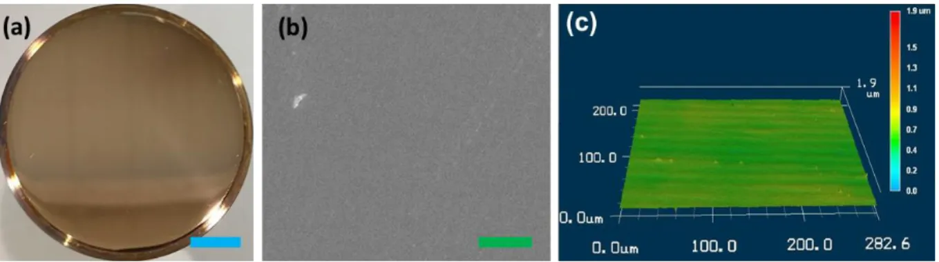
Figure 2.1 The mirror-finished copper surface: (a) photo, (b) SEM image, and (c) 3-D
profile. Blue scale bar: 10 mm. Green scale bar: 5 μm. 31
Figure 2.2 The TiO2 sputtered surface: (a) photo, (b) SEM image, and (c) 3-D profile.
Blue scale bar: 10 mm. Green scale bar: 500 nm. 32
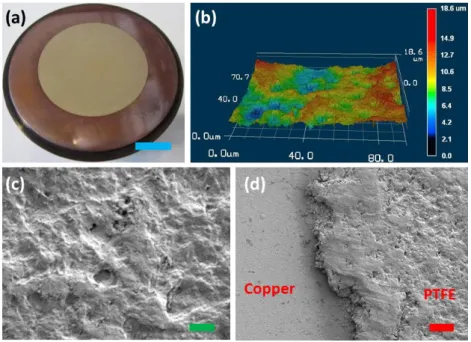
Figure 2.3 (a) A photo and (b) 3-D profile of the PTFE-spray-coated surface. Blue scale bar: 10 mm. SEM images of (c) the center region of the coating and (d) the border with a copper substrate. Green scale bar: 10 μm. Red scale bar: 30 μm. 33 Figure 2.4 (a) A photo of a TiO2 surface coated with the Polymer-modified HNT (P-
HNT), whose diameter is 6 mm. Blue scale bar: 10 mm. SEM images of P-HNT coating taken from (b) the top and (c) an inclined angle. Green scale bar: 50 μm.
Red scale bar: 1 μm. 34
Figure 2.5 (a) A photo of a copper surface spotted with the Ni/TFEO electroplating. Blue scale bar: 10 mm. (b) A 3-D profile and (c), (d) SEM images of the plated surface.
v
Green scale bar: 10 μm. 36
Figure 3.1 A schematic of the “open” type experimental system, which consists of a pool boiling apparatus (1-11) and peripheral equipment (12-23). 38 Figure 3.2 A schematic of the “closed” type experimental apparatus. 39
Figure 3.3 A schematic of the heat transfer block. 40
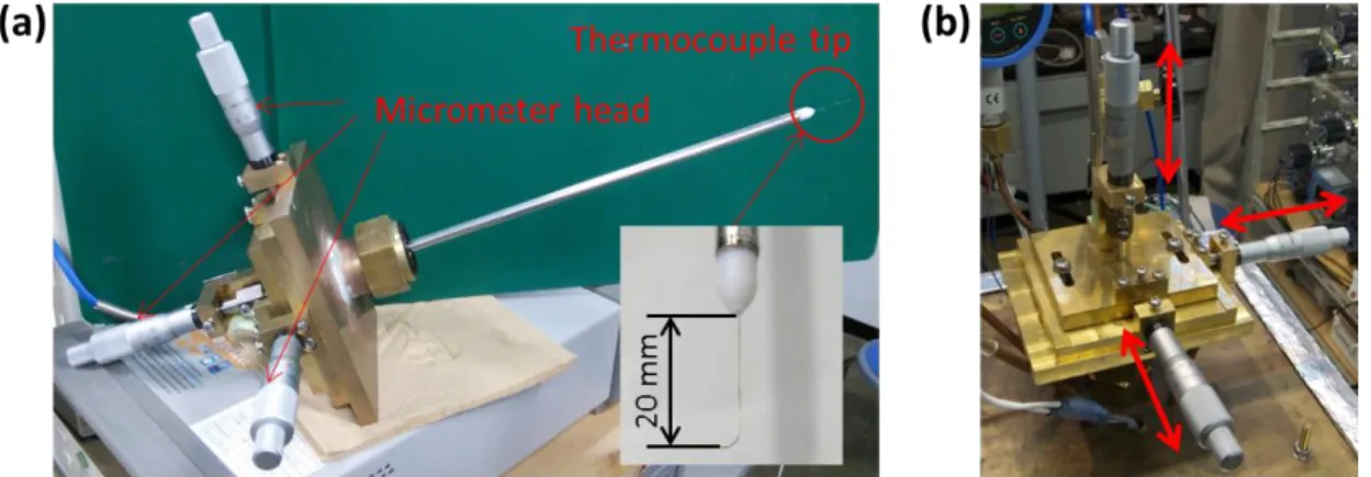
Figure 3.4 Schematic of the degassing procedure in the pure subcooled condition. A red- coloring of the valve numbers (I-VI) means the valve being opened. 42 Figure 3.5 (a) A departed bubble captured by the high speed camera. A bubble departure
diameter was measured as an average of vertical and horizontal widths of the bubble.
(b) Length scale of captured videos was calibrated by capturing a ruler putted above
the hydrophobic spot. 46
Figure 3.6 (a) A device for measurement of a temperature profile inside a bubble, which can be mounted onto the boiling vessel (b). The tip of the thermocouple can be precisely moved in three-dimensions with the help of a three-axis linear translation
positioner. 47
Figure 3.7 Comprasion of boiling curves of the mirror-finished copper surface at ΔTsub = 20 K under the gassy and pure subcooled conditions. The arrows indiacte ONB, and the black solid line is calculation of Lloyd and Moran’s correlation, eq. (3.7) and
(3.8). 48
Figure 3.8 Comparison of boiling behavior of the mirror-finished copper surface at ΔTsub
= 20 K and ΔTsat ≈ 13, 16, 22 K under (a) gassy and (b) pure subcooled conditions.
For the pure subcooled condition, the boiling behavior at ΔTsat ≈ 13 K is omitted
because it is still in the natural convection region. 50
Figure 3.9 (a) A photo of the biphilic surface having hydrophobic spots made of the PTFE
vi
spray (6 mm in diameter and 7 mm in pitch) on the TiO2 surface. Scale bar: 10 mm.
(b) Boiling curves of the biphilic surface at ΔTsub = 20 K under the gassy and pure
subcooled conditions. 51
Figure 3.10 Evolution of boiling behavior after ONB on the biphilic surface at ΔTsub =
20 K under the gassy subcooled condition. 53
Figure 3.11 Comparison of boiling behavior on the biphilic surface at ΔTsub = 20 K and ΔTsat ≈ 3, 6, 13 K under (a) gassy and (b) pure subcooled conditions. 54 Figure 3.12 Evolutions of bubble behavior in the gassy subcooled condition at ΔTsub =
20 K and ΔTsat = −1.2, 7.1, and 11.5 K. Scale bar: 3 mm. 56 Figure 3.13 (a) The bubble departure frequency, fd, and (b) diameter, dd, from a single
hydrophobic spot (with φ = 6 mm and θ ≈ 140o) coated on superhydrophilic surface (θ ≈ 0o). The results of Tashiro’s study [155] taken with a copper surface (θ = 70o) having a single hydrophobic spot (θ = 120-127o) are also plotted for comparison. (c)
Relationship of fd vs. dd. 57
Figure 3.14 (a) Evolution of a bubble shape with increasing ΔTsat at ΔTsub = 20 K. The red dash line represents the heating surface. Blue scale bar: 3 mm. (b) Plot of the distribution of a time-averaged bubble height, Hb, over various ΔTsat. Error bars for the horizontal and vertical axes show the measurement error and the maximal and minimal values for five seconds’ measurements, respectively. Blue dash line is calculation of eq. (3.10). (c) The model for eq. (3.10), where a bubble is assumed to be consist of a cylinder with Hc in height and r in radius, and a hemispherical cap 59 Figure 3.15 (a) A measurement procedure of vapor temperature inside a bubble. (b)
Temperature history during the measurement at ΔTsub = 20 K and ΔTsat = 6.1 K
under the gassy subcooled condition. 61
Figure 3.16 (a) Profiles of the vapor temperature, Tv, inside a bubble under the gassy
vii
subcooled condition at the various Tw. The detailed temperature profile at Tw = (b) 98.4 oC and (c) 109.6 oC. The red triangles represent Tw obtained from the temperature gradient inside the heat transfer block. Blue solid lines are the power approximations of Tv. Error bars indicate the maximal and minimal values for 10
seconds’ measurements. 62
Figure 3.17 (a) Temperature profiles inside a bubble under the pure subcooled condition at Tw = 103.8 and 108.3 oC. For comparison, the results of the gassy subcooled condition at similar Tw are included. (b) The partial pressures of non-condensable gas, Pg, inside a bubble calculated from the minimum values of Tv (summarized in
Table 3.3). 63
Figure 3.18 (a) Bubble behavior in the binary system (water + nitrogen), which are shown side by side with experimental observations (blue dash lines represent the heating surface). The color scale indicates fluid density normalized by the critical density of water. Nondimensional time, τ, is scaled by the bubble departure period. Contact angles of the yellow- and green-colored portions of the heating surface are set to be 120o and 10o, respectively. (b) A spatial distribution of nitrogen at the same instants as in (a), whose normalized density is represented by the color scale. (c) Bubble
behavior in the single component system. 65
Fig. 3.19 Evolutions of the local velocity distribution of the bubble interface in the (a) binary (water + nitrogen) and (b) single component (water) systems. (c) Total tangential mass fluxes integrated over the liquid-vapor interface, M║, versus
nondimensional time, τ. 67
Figure 3.20 Classification of heat transfer mechanisms of the gassy subcooled boiling from the biphilic surface. The data of pure subcooled boiling on biphilic and copper surfaces are plotted for comparison. NC: Natural convection. LHT: Latent heat
viii
transport. MC: Marangoni convection. NB: Nucleate boiling. 69
Figure 4.1 Biphilic surfaces with different diameters and pitches of hydrophobic spots, (a) Surface A (φ = 0.5 mm, p = 1.5 mm), (b) Surface B (φ = 0.5 mm, p = 3.0 mm), and (c) Surface C (φ = 1.0 mm, p = 1.5 mm). Blue scale bar: 10 mm. 72 Figure 4.2 Difference between the saturation temperatures at the liquid surface, Tsat,s,
and heating wall, Tsat,w, caused by the hydrostatic pressure of water column with a height of 120 mm, at the various liquid surface pressures, Ps. 74 Figure 4.3 (a) Boiling heat transfer comparison between Surface B (φ = 0.5 mm, p = 3.0
mm) and Surface D (mirror-finished copper) at P ≈ 102.3 kPa and 14.0 kPa (Tbulk ≈ 50 oC). Error bars show the maximal and minimal values of two minutes’
measurements in the steady state. (b) The corresponding h vs ΔTsat in the nucleate boiling region after ONB. Error bars show the measurement uncertainty. 77 Figure 4.4 Relationships between the standard deviation, SD, of T1 (measured at 3 mm
below the top surface) and q on (a) Surface D and (b) B. The data at and above the heat flux of arrowed points are in the nucleate boiling regime. Notice that the vertical axis of (a) is broken for visibility. Transient temperature measurements of T1 on (c) Surface D and (d) B at P ≈ 102.3 kPa and 14.0 kPa during two minutes in the steady state at q = 163-186 kW/m2. The red-dot-dash lines represent the mean values. 78 Figure 4.5 Evolution of boiling behavior on Surface D at q = 165.4 kW/m2 and P = 13.7
kPa, corresponding to the lower panel in Fig. 4.4c. Blue scale bar: 10 mm. 79 Figure 4.6 Evolutions of boiling behavior on Surface B at P = (a) 102.3 kPa and (b) 14.0
kPa, and various heat fluxes. Blue scale bar: 10 mm. 81
Figure 4.7 (a) Comparison of boiling curves between the three biphilic surfaces (Surface A, B, and C) at P ≈ 101.3 kPa and 13.8 kPa. The solid lines indicate the calculations
ix
of eq. (4.3) at the respective pressures. (b) The corresponding h vs ΔTsat in the nucleate boiling region. Error bars in (a) and (b) show the measurement uncertainty. 83 Figure 4.8 Effect of (a) a pitch and (b) diameter of the hydrophobic spots. The vertical
axis, hmeas/hcorr, is HTC normalized by the calculations based on eq. (4.3) for the
respective pressures. 84
Figure 4.9 Evolutions of boiling behavior on Surface A at P = (a) 101.3 kPa and (b) 13.6 kPa, and various heat fluxes. Blue scale bar: 10 mm. The red and blue arrows indicate bubble merging between neighboring spots and an isolated bubble, respectively. 85 Figure 4.10 Evolutions of boiling behavior on Surface C at P = (a) 101.5 kPa and (b)
13.8 kPa, and various heat fluxes. Blue scale bar: 10 mm. 87 Figure 4.11 (a) Boiling curves and (b) HTC (after ONB) obtained on Surface B at
different pressures. Error bars in (a) and (b) show the maximal and minimal values over two minutes’ measurements in the steady state and the measurement uncertainty, respectively. The solid lines in (a) represent the calculations of eq. (4.3) at P = 101.3 kPa and 6.9 kPa. (c) The corresponding hmeas/hcorr vs q. 89 Figure 4.12 Relationships between SD of T1 and q on Surface B at various pressures. Data
before ONB is omitted. Notice that the vertical axis is broken for visibility. 91 Figure 4.13 Evolutions of boiling behavior (left panels) and the corresponding transient
measurements of T1 during two minutes in the steady state (right panels) on Surface B at q ≈ 60 kW/m2 and P = (a) 50.7 kPa, (b) 21.8 kPa, (c) 8.8 kPa, and (d) 6.9 kPa.
Blue scale bar: 10 mm. The red-dot-dash lines in the right panels represent the mean
values. 91
Figure 4.14 Evolutions of boiling behavior (left panels) and the corresponding transient temperature measurements of T1 during two minutes in the steady state (right panels) on Surface B at P = 6.9 kPa, and q = (a) 164.0 kW/m2 and (b) 293.7 kW/m2.
x
Blue scale bar: 10 mm. The red-dot-dash lines in the right panel represent the mean
values. 93
Figure 4.15 Evolutions of single bubble behavior growing from a hydrophobic spot (φ = 0.5 mm) at P = (a) 103.9 kPa, (b) 49.2 kPa, (c) 33.0 kPa and (d) 21.5 kPa. The bottom panels in (c) and (d) are enlarged views of a vicinity of the heating surface (pointed out with a red-dot line). Blue scale bar: 2 mm. Green scale bar: 4 mm. 96 Figure 4.16 Behavior of the complete bubble departure at various pressures and heat
inputs with several spot diameters. Blue scale bar: 5 mm. 98 Figure 4.17 Bubble departure diameter, dd, of surfaces with different hydrophobic spot
diameters at various heat input, Q, and P. Blue and red solid lines are calculations
of eq. (1.12) and (1.13), respectively. 99
Figure 4.18 TPCL behavior map (pinned or depinned). The vertical axis is the system pressure normalized with P*, corresponding the pressure where dZuber* becomes equal
to dCole. 101
Figure 4.19 Evolutions of a bubble height, H, and width, W, (top panels) and averaged bubble radius, rave, (bottom panels) under (a) pinned and (b) depinned conditions, where rave is derived by taking an average of H and W. Under the depinned condition,
depinning of TPCL occurs at the arrowed point. 102
xi
List of Tables
Table 1.1 Summary of previous works about (super)biphilic surfaces. 22
Table 2.1 Sputtering conditions. 31
Table 2.2 Summary of surface properties and fabrication methods. 36
Table 3.1 ΔTONB [K] corresponding to Fig. 3.7. 48
Table 3.2 ΔTONB [K] corresponding to Fig. 3.9b. 52
Table 3.3 The minimum values of the vapor temperature, Tv,min, at various Tw. 63
Table 4.1 Surface information. 73
Table 4.2 ΔTONB [K] corresponding to Fig. 4.3a. 77
Table 4.3 Two characteristic regions in the boiling curves, shown in Fig 4.7(a), represented by n ≈ 3 and 1.3 for the equation of q ~ ΔTsatn. 88 Table 4.4 The effect of the pressure level on ΔTONB of Surface B. 89 Table 4.5 Comparison of the present result and recent studies for enhancement of sub-
atmospheric pool boiling of water and water-based liquid. 94
xii
Nomenclature
C solubility mol/mol
d diameter m
dc contact diameter m
D Diffusion coefficient m2/s
f frequency Hz
fA area fraction -
g acceleration due to gravity m/s2
h heat transfer coefficient W/(m2・K)
H height m
He Henry’s constant Pa/mol
la Laplace’s coefficient m
L total length of the bubble interface m
Llv latent heat of vaporization J/kg
M║ total tangential mass fluxes integrated over the bubble interface
kg/(m・s)
p pitch of hydrophobic spots m
P pressure Pa
Patm atmospheric pressure Pa
q heat flux W/m2
Q amount of heat W
r radius m
rc radius of a cavity m
Ra arithmetic average roughness m
Rf Roughness factor -
xiii
t time or period s
T temperature oC
ΔTsat degree of superheat K
ΔTsub degree of subcooling K
ΔTONB wall superheat at the onset of nucleate boiling K
x distance m
Greek symbols
γ interface energy J/m2
δ thickness of superheated liquid layer m
θ contact angle o
λ thermal conductivity W/(m・K)
ν kinetic viscosity m2/s
ρ density kg/m3
σ surface (interface) tension N/m
τ nondimensional time -
φ diameter of hydrophobic spots m
Subscripts
b bubble
bulk bulk
c copper
d bubble departure
g gas phase
l liquid phase
xiv lv liquid-vapor interface
min minimal value
s liquid surface
sat saturated condition sl solid-liquid interface sv solid-vapor interface
v vapor phase
w heating surface
Dimensionless numbers
Bo Bond number
Ja Jacob number
Nu Nusselt number
Pr Prandtl number
Ra Rayleigh number
1
Chapter 1
Introduction
1.1 Background
Boiling is a familiar phenomenon, experienced in our daily life such as food preparation and sterilization treatment. Importance of boiling phenomenon in the industrial field dramatically increased in the 1730s, when the first reliable steam engine was invented by James Watt. Steam engines, needless to say, convert heat energy of steam generated in a boiler to mechanical work. From the Watt’s invention, boilers have been used for power sources of trains, ships, and power plants. Boiling phenomenon in boilers plays a crucial role in the present-day society, for instance, power sources for steam turbines of thermal and nuclear power plants and heating and humidification in the food processing field [1, 2]. Boiling is also in wide use as an efficient way to cool high-temperature objects. In the steel-making process, good understanding and control of boiling behavior are essential because hot steel plates are cooled down by evaporation and boiling of splayed water droplets [3]. Thermosyphons, a heat transfer device using boiling and condensation, have been applied for electronics cooling because of their superior performance and energy saving [4, 5]. The superconducting technology, utilized in MRIs (Magnetic Resonance Imaging) and linear motor cars, requires cooling to a very low temperature, which is achieved with boiling of helium or nitrogen [6, 7]. In addition, refrigerators and air-conditioners draw heat from a low-temperature heat source through boiling and release it to a high-temperature heat source through condensation with the help of a heat
2
pump. Applications of the heat pumps are not only in the former examples but also in various fields: EcoCute (which has been introduced as energy saving equipment), utilization of geothermal energy, and waste heat recovery systems [8-10].
As mentioned above, boiling phenomenon is widely used in both the private and industrial sectors. Hence, improvement of boiling heat transfer based on understanding of the phenomenon has a great impact on our society. In 2010, for example, data centers consume 1.3% of the total electricity use in the world [4]. The value is expected to further increase due to the increasing demand in developing and industrializing countries. Almost 50% of that electricity consumption is used for thermal management of CPUs in order to maintain their temperature appropriately [11, 12]. Therefore, the enormous energy consumption in the data centers can be significantly reduced by enhancement in the efficiency of cooling devises through improvement of boiling performance. Energy consumption of heating, cooling, and hot water supply in the house hold sector exceeds seven percent of the total energy consumption of Japan [13]. According to NEDO (New Energy and Industrial Technology Development Organization), moreover, unused energy of 1000 billion kWh (comparable to the annual gross generation in Japan) is annually discarded as waste heat [14]. Developments of high-efficiency heat exchangers and heat pumps are capable of significantly contributing to the resolution of these problems.
Now, as for the history of boiling research, scientific treatment of boiling phenomenon began in the 1930s, more than 100 years later than the industrial revolution started from the invention of the steam engine [15, 16]. Jakob and Fritz published an article about bubble behavior and boiling heat transfer in 1931. At around the same time, Nukiyama [17] carried out pool boiling experiments of water around a platinum wire heated by Joule effect and obtained the Nukiyama curve (so-called boiling curve) which gives the entire picture of characteristics of boiling heat transfer. Although some important papers were published after
3
that, boiling phenomenon was actively studied from the 1950s to 1960s on the back of significant developments of nuclear power and aviation technologies [18]. In this period, various studies were conducted with an aim to reveal mechanisms of pool boiling [19-23], and empirical equations and physical models widely used today were proposed: the correlations for nucleate boiling heat transfer of Rohsenow [24], Kutateladze [25], and Nishikawa and Yamagata [26], the CHF (Critical Heat Flux) model of Zuber [27], and the correlation for film boiling heat transfer of Berenson [28]. In the 1970s, enhancement of boiling performance attracted much research efforts due to the increased seriousness of the energy problem. Consequently, the demand resulted in development of high performance heating surfaces, such as Thermoexcel [29] and UC High Flux [30]. Thence, many works have been conducted for further enhancement of boiling performance and unveiling of boiling phenomenon with various techniques to this day. The former includes nano-fluids [31], fluid mixtures (immiscible mixtures, high-carbon alcohol aqueous solutions, and so on) [32, 33], nano/micro-structured surfaces [34, 35], wettability modification of a heating surface [36], and honeycomb porous plates [37]. On the other hand, examples of the latter are listed as below: observation of solid-liquid contact behavior by means of the total reflection method [38], local and instantaneous measurements of heat flux and wall temperature with MEMS (Micro Electro Mechanical Systems) sensors or high-speed infrared cameras [39-41], and measurements of micro-layer thickness by applying the laser distinction method [42].
In addition to the above, multifarious works are being undertaken, and it is extremely difficult to grasp all of them. The number of the scientific papers with the word of “boiling” in their title, abstract, or keywords has been steadily increasing from 1330 in 2000 to 2510 in 2010, and reached 3040 in 2016. The reason that boiling research attracts increasing attention even now, more than 80 years passed from Nukiyama’s work, is because boiling is a highly-complex phenomenon accompanying phase change as well as has a vital engineering importance.
4 1.2 Basics of boiling phenomenon
In this section, an overview of boiling phenomenon is introduced, focusing on pool boiling which is the target of the present study.
1.2.1 Boiling curve
Characteristics of boiling heat transfer can be represented by a graph of heat flux, q, against wall superheat, ΔTsat, namely boiling curve. Figure 1.1 shows a typical boiling curve obtained for upward facing surfaces or horizontal wires with controlled heat flux [43].
Schematics of boiling modes are also displayed above the graph.
By applying heat to a surface, heat transfer is initially dominated by natural convection without the case of microgravity. When ΔTsat reaches a certain value (point A in Fig. 1.1), a vapor bubble is generated on the surface, resulting in the transition from natural convection to nucleate boiling. The point A is called the onset of nucleate boiling (ONB) point and the corresponding ΔTsat is defined as wall superheat at ONB, ΔTONB. Since heat transfer coefficient (HTC) of nucleate boiling is one to two orders of magnitude greater than that of natural convection, a gradient of the boiling curve increases significantly. In boiling of low-surface- tension liquids or on low-surface-energy substrates, a number of nucleation sites are activated simultaneously at a higher ΔTsat, causing a decrease in ΔTsat for a constant q (in other words, an overshoot appears). The overshoot, however, is not seen on boiling curves obtained with decreasing q.
In the partial nucleate boiling region, corresponding to the early stage of nucleate boiling, isolated bubbles depart from the surface (Region II in Fig. 1.1). The number of nucleation sites and frequency of bubble departure increases as q rises. As a result, bubbles start to merge with neighboring and foregoing bubbles. Such boiling behavior is defined as fully developed nucleate boiling (Region III in Fig. 1.1). In the region, jet-like release of bubbles occurs, and mushroom-
5
Figure 1.1 A typical boiling curve obtained for upward facing surfaces or horizontal wires with controlled heat flux. Schematics of boiling modes are displayed above the graph.
shaped bubbles, supported by several stems, are formed on the surface.
By further increasing q, liquid flow toward the surface tends to be obstructed because of departure of large bubbles with a higher frequency. Finally, the heat transfer mode turns in to film boiling, where there is no contact between the liquid and surface due to a vapor blanket formed at the solid-liquid interface. The corresponding q (point C in Fig. 1.1) is called the critical heat flux (CHF). HTC of film boiling is remarkably low owing to poor heat transfer of conduction through the vapor film and radiation from the substrate. In the case of controlled heat flux, therefore, ΔTsat sharply jumps up once q reaches CHF. Passing through transient boiling (Region IV in Fig. 1.1) immediately, the boiling state is stabilized at point E in Fig.
6
1.1. On the other hand, film boiling is maintained at q below CHF when boiling curve is taken with decreasing q. It suddenly changes back to nucleate boiling at a certain value of q (point D in Fig. 1.1), which is far below CHF. The heat flux, where the vapor film collapses, is defined as the minimum heat flux (MHF).
Transition boiling, having characteristics of both nucleate boiling and film boiling, is a very unstable boiling mode where ΔTsat increases as q decreases. Stable transient boiling is, thus, obtainable only in experiments with controlled wall temperature.
1.2.2 Boiling incipience
When a spherical vapor bubble with a radius of r exists in liquid at a uniform temperature of T in equilibrium, the force balance at the interface is described as follows (Laplace’s equation).
r P
Pv l 2/ (1.1) where Pv and Pl are pressures in the vapor and liquid phase, and σ is surface tension. The liquid temperature must be higher than the saturation temperature (that is, superheated condition) to enable bubble nucleation because a pressure inside the bubble is higher than that of the liquid side [44].
From the Clapeyron-Clausius equation,
l v
sat lv v l
d
satd
T
L T
P
(1.2)and eq. (1.1), a degree of liquid superheat necessary to form a stable vapor bubble can be estimated as
r L
T r
L T T
lv v
sat lv
v l
v l sat sat
2 2
(1.3) where ρis density and Llv is latent heat of vaporization. According to this equation, it is clear that a bubble with a smaller r requires a higher ΔTsat.
7
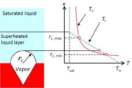
There are two types of bubble nucleation: homogeneous nucleation and heterogeneous nucleation. In the homogeneous nucleation, bubble nucleation occurs inside liquid, not including any gas or vapor, at a temperature much higher than Tsat. On the other hand, bubbles are formed at the solid-liquid or liquid-liquid interface in the heterogeneous nucleation. ONB in common boiling is due to the heterogeneous nucleation, where defects or cavities on a heating surface work as nuclei.
Based on the schematic shown in Fig. 1.2, ΔTsat needed for bubble nucleation from a cavity with a radius of rc is calculated as follows. From eq. (1.3), to enable bubble growth from the cavity, a vapor temperature must satisfy the following equation,
c lv v
sat sat
v
2 r L T T
T
(1.4) Here, it is assumed that liquid adjacent to the surface has a linear temperature profile in the vertical direction.
) 1
sat(
sat
l
T x T
T (1.5) where δ is thickness of the superheated liquid layer, given by using thermal conductivity of the liquid phase, λl.
q Tsat
l
(1.6) To maintain the bubble with a radius of rc, Tl ≥ Tv must be satisfied at its apex (x = rc).Hence, from eq. (1.4), (1.5), and (1.6), 2 0
lv v
sat l c
sat 2 l
c
L q
r T q r T
(1.7)
is derived. The solution of the above equation leads to a range of rc for cavities activated at a given ΔTsat as below.
2
sat l lv v
sat sat
max l c min
1 8
2 1 L T
q T q
r T
(1.8)
Incidentally, van Steralen and Cole extensively summarized experimental data, and proved
8
Figure 1.2 Condition for heterogeneous nucleation from a conical cavity with a radius of rc.
that the actual bubble nucleation from cavities on a substrate is not always due to the heterogeneous nucleation, but highly depends on gas or vapor pre-existing inside them. When gas is trapped inside a cavity, the equilibrium condition (eq. (1.1)) can be rewritten by the following replacing of its right side.
g
2
2 P
R
R (1.9) where Pg is partial pressure of the gas.
1.2.3 Bubble growth and departure
Bubble motion is closely related to heat transfer mechanisms of nucleate boiling. In common nucleate boiling, bubbles repeat nucleation, growth, and departure (this duration is defined as a growth period) with intervals (so-called a waiting period), as shown in Fig. 1.3.
Such periodic behavior is called bubble cycle. Here, the waiting period is time required for a reformation of the superheat liquid layer disturbed during the growth period.
A size of a bubble departing from a surface is determined by the balance of forces acting on the bubble: buoyancy, adhesion force (surface tension), drag force, and surrounding liquid
9
Figure 1.3 Schematic of bubble cycle.
motion [45]. Fritz and Zuber respectively proposed correlations of the bubble departure diameter, dd, considering only the static balance between surface tension and buoyancy force.
In Fritz’s model, a contact angle, θ, of a bubbles is assumed to be kept constant, although a contact diameter, dc, changes as the bubble grows. On the other hands, Zuber’s model considers a constant dc and varying θ. With the Bond number, Bo, the two correlations are expressed as follows.
0209 .
2 0
1
Bo (1.10)
l v
12c 2
1 6
d g
Bo (1.11)
l v2
d
d g
Bo (1.12) where g is acceleration due to gravity and a unit of θ is degree.
The above equations cannot be applied for boiling at low pressures where bubbles largely expand due to a reduced ρv. Cole, therefore, derived the following correlation by adopting Jacob number, Ja, to reproduce pressure dependency of dd.
Ja
Bo12 0.04 (1.13)
lv v
sat pl l
L T Ja c
(1.14)
10 where cpl is heat capacity of liquid.
1.2.4 Heat transfer mechanism of nucleate boiling
In the nucleate boiling, which has a superior HTC, heat is transferred with various heat transfer mechanisms as shown in Fig. 1.4 [46]. During bubble growth process (Fig. 1.4 (a)), a thin liquid layer with a thickness of 1-10 μm (micro-layer) is trapped between the hemispherical bubble and the surface. Evaporation of this microlayer removes heat from the surface in the form of the latent heat (qml). A plenty amount of heat is transferred though the micro-layer because temperatures at its top and bottom are the saturation and wall temperature―a very steep temperature gradient is generated across the thin layer. In a vicinity of the three phase contact line (TPCL), a reduced thickness of the micro-layer brings enlargement of heat transfer (qcl). Evaporation also takes place at the liquid-vapor interface in the superheated liquid layer (qsl). Additionally, the growing bubble induces liquid motion (so-called, microconvection), resulting in enhanced convective heat transfer (qmc). In a region free from influence of the bubble, heat transfer is dominated by natural convection (qnc).
When the bubble grows up to a certain size, it shifts to the departure process due to an increased buoyancy force. qml has a minor or no role since the micro-layer has been dried out in the growth process. Although qcl still exists, it is expected to be smaller than that during
Figure 1.4 Heat transfer mechanism during (a) bubble growth and (b) departure processes.
11
the growing process, because an advancing contact angle is greater than a receding contact angle, leading to a thicker liquid layer beneath the bubble. qsl contributes to the heat transfer in the same manner as the growth process, excluding a case of subcooled boiling. As the bubble base shrinks, a high-temperature part of the surface, which was being covered with the vapor patch, is rewetted by the surrounding liquid. Consequently, transient conduction from the surface to the liquid occurs (qtc). The shrinkage of the bubble base also brings the microconvection toward the center axis of the bubble (qmc). A wake induced by the bubble departure causes additional microconvection.
1.2.5 Factors affecting pool boiling
There are numerous factors affecting heat transfer characteristics of pool boiling, which can be divided into two types: fluid-side and surface-side [47]. Thermophysical properties of fluid (i.e. density, heat capacity, viscosity, thermal conductivity, latent heat of vaporization, and surface tension) have remarkable influence on boiling features. Since these properties are functions of temperature and pressure, a degree of subcooling, ΔTsub, and system pressure, P, are the representatives of the fluid-side factors. Moreover, liquid level and a degree of gravity affect boiling performance. On the other hand, the surface-side parameters include surface geometry (roughness and structures), inclination, size, thickness, and wettability in addition to thermophysical properties [48, 49]. Fig. 1.5 summarizes how an increase in the respective parameters influences boiling curve.
The details of each effect are as follows. CHF and MHF are improved, and HTCs in transition and film boiling are enhanced as ΔTsub increases [50, 51]. With regard to the nucleate boiling regime, influence of ΔTsub cannot be described sweepingly, because it has two opposing effects on HTC: reduction of the number of nucleation sites and bubble departure frequency, and improvement of convective heat transfer owing to a decreased liquid temperature [52].
12
Figure 1.5 Effects of various parameters on boiling curve.
Bubbles hardly detach from a surface under microgravity conditions, resulting in deterioration of HTC and CHF [53-55]. As system pressure rises, ONB is promoted because the increase in the saturation temperature of bubble due to Laplace pressure becomes insignificant. As a result, HTC of nucleate boiling is enhanced [56]. CHF is also improved with increasing pressure in the range up to about one third of the critical pressure; however it decreases monotonically at the higher pressures [57, 58]. HTC in the nucleate boiling regime is enhanced when liquid level is lower than a certain value [59]. The critical liquid level depends on a kind of fluid, which is about 5 mm for distilled water.
Surface roughness, Ra, is closely related to formation of bubble nuclei. Generally, nucleate boiling on a rougher surface show better HTC [60, 61]. However, Ra becomes less influential in the film boiling region where the solid-liquid contact is completely interrupted. Inclination of a heating surface affects boiling performance remarkably. HTC and CHF are minimized with a downward facing surface [62-64]. When a characteristic length of a heating surface is smaller
13
than 20 times of the Laplace coefficient, CHF increases with decreasing characteristic length since liquid supply in the direction along the surface is promoted [65]. HTC becomes greater by using a heating surface with a thickness less than a certain value. The critical thickness differs from material to material [66, 67]. Surfaces with porous [68-70] or fin structures [71, 72]
lead to superior HTC and CHF because of an increased nucleation site density, enlarged surface area, and wicking effect. Surface wettability extensively affects boiling curve from ONB to MHF. Its detail are described later in Section 1.4.
In addition to the above, boiling performance can be enhanced by adding external forces such as electric fields [73, 74] and ultrasonic waves [75, 76].
1.3 Surface wettability
The present study deals with boiling on wettability-modified surfaces. In this section, hence, an overview of wetting phenomena and an evaluation method of wettability are introduced.
Molecules inside liquid are attracted by surrounding molecules, and these forces are isotropic. Conversely, molecules at the liquid-gas interface are pulled toward the inner part of the liquid due to a weaker attractive force from the gas phase. This force imbalance gives rise to surface tension [77]. The molecules on the surface also in a state of losing part of its cohesive energy, that is, they has a higher free energy. This surplus is the origin of surface energy.
Figure 1.6 shows the balance of three interfacial forces when a liquid droplet is put on a solid substrate, where σlv, σsv, and σsl are interfacial tensions of the liquid-vapor, solid-vapor, and solid-liquid interfaces, respectively. Based on the force balance in the horizontal direction, the following relation is derived (Young’s equation).
lv sl sv lv
sl
cos sv
(1.15) where θ is contact angle and γ is interfacial energy. σlv is called surface tension and commonly represented by σ. In this article, σ is also used unless otherwise mentioned. As seen from eq.
14
Figure 1.6 Equilibrium of three interfacial forces at the three phase contact point.
(1.15), θ is decided by combination of kinds of liquid and solid. If the liquid has a high-affinity for the solid, θ is small, and vice versa. A degree of wettability is usually represented by using θ due to ease of measurement. In the case of water, for instance, surfaces whose θ is below and above 90o are called hydrophilic and hydrophobic, respectively. In addition, there are terms for the two extreme cases: superhydrophilic (θ < 10o) and superhydrophobic (θ > 150o).
Wettability is in a close connection with surface roughness. Wenzel [78] modified Young’s equation, basing on the concept that interface tensions rises with increasing actual surface area, as follows.
( ) cos
cos
lv sl
sv Rf
Rf
(1.16) where θ and θ’ are contact angles of flat and rough surfaces, respectively. Roughness factor, Rf, is the ratio of the actual surface area to the projected area. Since Rf is necessarily larger than unity, θ’ < θ if θ < 90o, and θ’ > θ if θ > 90o. In other words, hydrophilic surfaces become more wettable and hydrophobic surfaces become less wettable as surface roughness increases.
Although Wenzel’s model is available for a surface having a relatively small roughness, it cannot be applied to a surface with so large Rf that the absolute value of the right side of the equation exceeds unity.
Cassie and Baxter [79] proposed a model, shown in Fig. 1.7, for the wetting phenomenon on surfaces with heterogeneous wettability. A contact angle, θ’, of a surface, consisting of two
15
Figure 1.7 Schematic of Cassie-Baxter model.
components of x (with θx) and y (with θy), is described with the following equation by using their area fraction, fA : (1−fA).
y A
x A lv
y,sl y,sv A x,sl
x,sv
A( ) (1 )( ) cos (1 )cos
cos
f f f f
(1.17)
Additionally, they extended their model for the case that one of the components is air (assumed here to be y), and derived the equation by considering θ of air is 180o (because water forms a spherical droplet in the atmosphere), as below.
1 cos
cos fA x fA (1.18) This equation means that contact angle becomes large when air is trapped inside grooves on a rough surface without water penetrating into them. The concepts of Wenzel’s and Cassie- Baxter’s model are essential to fabricate superhydrophobic surfaces.
1.4 Literature survey
Wettability is one of the dominant parameters of boiling phenomenon. Wettability modification of a boiling surface has been extensively studied owing to its great potential for enhancement of boiling performance. In this section, a review of previous works on pool boiling is given while focusing on the following three points: wettability modification, noncondensable gas inside boiling mediums, and system pressure.
16
1.4.1 Improvement of boiling characteristics through wettability modification
1.4.1.1 Hydrophobic and superhydrophobic surfaces
Research for boiling features on wettability-modified surfaces has a long history. Costello and Frea [80] reported 75% reduction of CHF on a less wettable surface made by a silastic coating, in 1965. Torikai and Yamazaki [81] studied boiling characteristics and the condition of contact between bubbles and a substrate with a uniform hydrophobic surface of a silicone- coated conductive glass, and obtained the following results: (i) The bottom of bubbles was generally in the dry state, namely, no micro-layer beneath the bubbles; (ii) The heating surface was divided into two regions based on bubble behavior. Bubble growth and departures took place frequently on one part, and bubbles hardly detached from the surface while slowly expanding and shrinking on the other. Such boiling behavior was similar to transient boiling;
(iii) On the hydrophobic surface, ONB occurred at lower ΔTsat than that on a hydrophilic surface, resulting in an enhanced HTC at lower q. However, HTC in high q region deteriorated, and CHF was significantly reduced. The transient-boiling-like behavior was also observed by Hasegawa et al. [82, 83], who used stainless plate (20 × 100 mm2) entirely or partially coated with a silastic adhesive. They subsequently concluded that the boiling mode was essentially nucleate boiling (transient-boiling-like nucleate boiling), because periodic bubble departures occurred, and additionally q increased as ΔTsat rose in the region.
Takegawa et al. [84] investigated a heat transfer mechanism on a hydrophobic surface through observations of bubble behavior with a high-speed camera. According to the study, heat transfer on the hydrophobic surface was dominated by the followings: (i) latent heat transportation of bubbles and (ii) convection induced when departing small bubbles coalesce with surrounding large bubbles. They also reported that both a bubble departure diameter and frequency monotonically became greater with increasing q on the hydrophobic surface, unlike on a normal surface.
17
Yasukawa [85] revealed that a single bubble grew over the entire surface without an occurrence of the transient-boiling-like nucleate boiling on a narrow hydrophobic surface (with a diameter of 10 mm). Investigating boiling characteristics at ΔTsat up to 200 K, they obtained the following results: (i) At ΔTsat from 6 to 200 K, a growing bubble firstly formed concavity at a lower part of its interface, followed by a partial bubble departure of the above-neck-portion.
As a results, a thin vapor film remained on the surface after the departure, which interrupted the solid-liquid contact; (ii) q just monotonically increased as ΔTsat increased, leading to absences of CHF and MHF points on boiling curve; (iii) A gradient of the boiling curve was similar to that of film boiling.
To comprehend the effect of hydrophobicity on boiling characteristics, Torikai et al. [86]
carried out experiments by using surfaces (with 10 mm in diameter) applied three different hydrophobic coatings: a Teflon spray (θ = 100o), silicone adhesive (θ = 110o), and silicone cladding (θ = 124o). Boiling curves similar to Yasukawa [85] were obtained on the silicone adhesive and silicon cladding (having the higher hydrophobicities). On the other hand, the Teflon-spray-coated surface was not covered by a single large bubble, whose boiling curve had the same tendency with normal surfaces, that is CHF and MHF points appeared.
Num et al. [87] studied behavior of a single bubble on a smooth hydrophobic surface (Teflon coating, θ = 118-134o) on which an artificial cavity with a diameter of 7 μm was manufactured. They found that, a bubble departure diameter and period on the surface were increased by 7 and 60 times compared with those on a bare silicon surface (θ = 33-46o), respectively, due to an extended contact diameter of the bubble. Furthermore, the bubble departure followed a short “necking” period (where the bubble interface was constricted), and then a tiny vapor bubble was remained on the surface after the detachment. The residue worked as a nucleus of the next bubble. This means an absence of a waiting period in the bubble cycle, which agrees well with the observations conducted by Yasukawa [85] and Torikai et al. [86].
18
They also performed a numerical simulation by using the level-set method. Although some assumptions were made (θ was kept constant at 120o and evaporation of a micro-layer was omitted), a numerically obtained departure diameter and period showed good agreement with their experimental data within 5 and 7%, respectively.
Takata et al. [88] successfully fabricated a superhydrophobic surface (θ = 150-170o, d = 30 mm) by means of a nickel electroplating containing fine PTFE particles. On such surface, ONB occurred at an extremely low ΔTsat (= 2.15 K), and a vapor film covering the whole surface was formed at ΔTsat ≈ 6 K. HTC of the surface was higher than that of a plain copper surface at ΔTsat ≤ 15 K; however, it tended to deteriorate at higher ΔTsat. Moreover, CHF and MHF points were absent in its boiling curve. Hsu and Chen [89] also obtained the similar results by using a surface with θ ≈ 149o.
From the above studies, the characteristics of boiling on (super)hydrophobic surfaces are summarized as follows.
ONB and HTC at lower ΔTsat are enhanced, although HTC at higher ΔTsat and CHF deteriorate.
A single bubble grows over the entire surface when a narrow or high-hydrophobic heating surface is used. In that case, CHF and MHF points are absent in boiling curve.
A contact diameter of a bubble expands, resulting in a large bubble departure diameter and period.
Bubble departure follows a short “necking” period, and then part of vapor is remained on a surface after the detachment. This partial departure leads to a bubble cycle without a waiting period.
1.4.1.2 Hydrophilic and superhydrophilic surfaces
Costello and Frea [80] hydrophilized a surface by depositing scale on the surface through
19
repetition of boiling experiments with tap water. Using the hydrophilic surfaces, they found CHF was improved by 50% compared with a surface without scale. Since then, many studies, utilizing the same hydrophilizing method, were carried out [90-93], and enhancements of MHF, CHF, and HTC of transition boiling were found. Among of those, Maracy and Winterton [93]
succeeded to obtain a superhydrophilic surface (θ ≈ 0o) by repeating boiling experiments 36 times. They reported CHF was improved with decreasing θ.
Takata et al. [94, 95] prepared a superhydrophilic surface (θ ≈ 0o), using the unique characteristics of TiO2 that it is super-hydrophilized by an irradiation of ultraviolet (UV) light.
On the superhydrophilic surface made of a TiO2-coated cooper substrate, compared with a bare copper surface, about two times improvement of CHF and 100 K increase in MHF temperature were obtained, in addition to enhancement of HTC in the nucleate boiling region. Various fabrication methods were developed in the past decade such as the photocatalytic effect of TiO2
[96, 97], coating with nano-particles [89, 98-100] and nanowires [101, 102], and surface oxidizing treatments [103, 104]. Although the enhancement of CHF was confirmed in all of those studies, HTC of nucleate boiling increased in some cases [94, 99, 101] and decreased in the others [98, 100, 103]. This is supposed to be because the hydrophilization of a surface brings two opposing effects: the hydrophilic coatings induce micro-nano structures which serve as favorable nucleation sites, at the same time, the coated layer becomes thermal resistance.
Num et al. [105] carried out a detailed investigation of behavior of a single bubble on a superhydrophilic surface (θ = 7.5±2o) having an artificial cavity (15μm in diameter). On the surface, bubbles maintain their almost-perfect-spherical shape during growing and departure processes. A bubble departure diameter and period are respectively reduced by 2.5 and 4 times, compared with a bare silicon surface (θ = 44o), due to suppressed expansion of the bubble base.
From the above studies, the characteristics of boiling on (super)hydrophilic surfaces are summarized as follows.
20
CHF, MHF, and HTC of transition boiling are improved.
The effect of hydrophobic coatings on HTC in the nucleate boiling region depends on their surface topology and thickness.
A bubble departure diameter and period decrease because of a small contact diameter of a bubble.
1.4.1.3 Biphilic and superbiphilic surfaces
Superiority of use of a surface with heterogeneous wettability, not uniform hydrophilic or hydrophobic, was shown by Young and Hunmmel [106] in 1964. They made a hydrophilic surface having hydrophobic domains by means of applying a tetrafluoro resin into holes irregularly distributed on a SUS304 surface (supposed to be slightly hydrophilic). On such surface, vigorous bubble departure occurred at q = 13 kW/m2 and ΔTsat = 2 K (ONB condition on a surface without the resin was q = 47 kW/m2 andΔTsat = 12 K). HTC reached 8.6 kW/m2 at ΔTsat = 8 K due to promoted liquid circulation by the departing bubbles, which was almost 18-fold of a plain SUS304 surface. Moreover, temporal fluctuation of ΔTsat in the steady state became very small on the heterogeneous wettability surface. All experiments were done at q <
315 kW/m2 (below CHF) in their study to avoid damage to the surface.
Takata et al. [107] carried out boiling experiments on copper surfaces (θ = 92o) with dot- or checker-patterned superhydrophobic coating (θ = 152o). HTC on the patterned surfaces was seven times greater than that on a plain copper surface at moderate heat fluxes. However, HTC deteriorated at ΔTsat > 8 K, and CHF was reduced. Observing boiling behavior, they also found bubbles were generated from only the coated domains, meanwhile the solid-liquid contact was maintained without bubble nucleation on the uncoated area. Additionally, a departure diameter of a bubble highly depended on a size of the hydrophobic domain since TPCL was pinned at the edge of the hydrophobic spot. In the paper, increase in CHF by replacing the