A uthor(s )
GY OT E N, Hidenori; HIR OMOT O, Masayuki; S A T O, T akashi
C itation
IE IC E T ransactions on Information and S ystems (2018),
E 101.D (2): 314-323
Is s ue D ate
2018-02
UR L
http://hdl.handle.net/2433/229141
R ig ht
©
2018 T he Institute of E lectronics, Information and
C ommunication E ngineers
T ype
J ournal A rticle
T extvers ion
publisher
PAPER
Special Section on Reconfigurable SystemsArea E
ffi
cient Annealing Processor for Ising Model without
Random Number Generator
Hidenori GYOTEN†a),Student Member, Masayuki HIROMOTO†,andTakashi SATO†,Members
SUMMARY An area-efficient FPGA-based annealing processor that is based on Ising model is proposed. The proposed processor eliminates ran-dom number generators (RNGs) and temperature schedulers, which are the key components in the conventional annealing processors and occupying a large portion of the design. Instead, a shift-register-based spin flipping scheme successfully helps the Ising model from stucking in the local op-timum solutions. An FPGA implementation and software-based evalua-tion on max-cut problems of 2D-grid torus structure demonstrate that our annealing processor solves the problems 10–104times faster than conven-tional optimization algorithms to obtain the solution of equal accuracy.
key words: combinatorial optimization problem, max-cut problem, Ising model, annealing, FPGA
1. Introduction
Efficient social infrastructures and systems are essential to our daily lives. It is desirable to reduce the logistics cost of supply chain, to shorten travel time, to minimize the distri-bution loss of energy resources, etc. Most of these practical problems are known to be formulated as combinatorial op-timization problems. However, it is very hard to obtain the optimal solutions in a practical time as the size of the prob-lems becomes large, mostly due to the exponential nature of their computational complexity. Although efficient heuristic algorithms have been actively developed[1]–[3], they still require unacceptably large computation time to obtain solu-tions, or the quality of the solutions becomes insufficient.
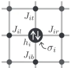
Besides these conventional heuristic algorithms, an al-ternative solver that utilizes theIsing modelis gaining in-creasing attention. The Ising model is a mathematical model of ferromagnetism in statistical mechanics[4]. The model consists ofspins, each of which takes one of two discrete states{+1,−1}. The spins are generally arranged in a lat-tice form as shown in Fig. 1. The spin’s value is determined such that the local energy of the spin decreases according to the states of the adjacent spins considering the interactions with adjacent spins, as shown in Fig. 2. This local update decreases the energy of the entire Ising model, which facili-tates to solve the problems in a highly parallel manner, thus achieving a fast optimization.
A quantum annealing computer, D-Wave[5], is one of
Manuscript received May 8, 2017. Manuscript revised September 8, 2017. Manuscript publicized November 17, 2017.
†The authors are with Department of Communications and
Computer Engineering, Graduate School of Informatics, Kyoto University, Kyoto-shi, 606–8501 Japan.
a) E-mail: [email protected] DOI: 10.1587/transinf.2017RCP0015
Fig. 1 Typical structure of the Ising model.
Fig. 2 A spin in the Ising model. Each spin has interactions with adjacent spins.
the Ising-model-based solvers, which emulates the behavior of the Ising model by quantum annealing[6],[7]. It is re-ported that the weak-strong cluster pair problem, which is one of the combinatorial optimization problems, has been solved 1.8×10⁸ times faster than simulated annealing[8].
However, a superconducting flux qubit, the key element of the D-Wave, requires cryogenic temperature during the op-eration. This makes the computer system significantly com-plex and expensive. Other approach includes CMOS anneal-ing[9]. It simulates the annealing of the Ising model on a general CMOS logic circuit, which realizes the circuit oper-ation at a room temperature. This method has advantages of inexpensive implementation and easier integration with con-ventional computer systems. Recent research includes an implementation of the CMOS annealing on FPGA[10]and a hardware architecture for fully-connected Ising model[11]. In this paper, we focus on the architecture based on the concept of CMOS annealing and propose an area-efficient annealing processor that can be implemented using fully digital circuits, such as in an FPGA. One of the most impor-tant challenges for the annealing processor is area efficiency. The performance of such processors directly depends on the parallelism achieved, i.e., the number of spins that can be implemented on a single chip. The spin itself can be eas-ily realized by a simple small circuit. However, the anneal-ing processor requires an additional function to simulate the
probabilistic behavior of the Ising model. Random number generators (RNGs) and temperature scheduler are typically adapted for this purpose, which have been occupying a large hardware resource, as in the case of[10].
In this work, we propose a novel shift-register-based spin flipper (SRSF) that helps the annealing process to con-verge without using random numbers. This approach signif-icantly improves the area efficiency of the annealing proces-sor by eliminating large RNGs, and thus improves its scala-bility. Our proposed annealing processor has the following three features: (1) a simple SRSF circuit that can emulate the annealing behavior, (2) scalable architecture that can be configurable for the size of the problems to solve, and (3) fully synthesizable digital design that can be easily imple-mented on an FPGA. Owing to these features, we can suc-cessfully implement a 2000-spin Ising model on an FPGA of moderate capacity to use as the accelerator of the combi-natorial optimization solver. We solve max-cut problems of 2D-grid torus structures by the proposed annealing proces-sor and compare its efficiency and accuracy to the existing software solvers. The experimental results show that our processor can find quasi-optimum solutions 10–104 times faster than the existing software solvers.
The contribution of this paper is summarized as fol-lows:
• An area-efficient annealing processor for the Ising model is proposed, which eliminates the resource-consuming random number generators, by employing a simple shift-register-based spin flipper with a negli-gible area overhead.
• The proposed processor is implemented on an FPGA and its performance is quantitatively evaluated using max-cut benchmark problems[12]. The results are also compared with software implementations.
• Our annealing processor can solve the max-cut prob-lems several orders faster than the existing fastest ap-proximation algorithm[1].
The rest of this paper is organized as follows. Section 2 provides preliminary knowledge about the Ising model. Sec-tion 3 proposes the architecture of our annealing processor and the SRSF methods to improve the area efficiency with-out using RNGs. Section 4 shows the evaluation and the results, and finally, Sect. 5 concludes the paper.
2. Ising Model
2.1 Definition
The Ising model[4] consists of a set of spins that are in-terconnected with each other with a weight. The connec-tion of the spins can take any topology, representatively a lattice form as shown in Fig. 1, which is a most typical ex-ample. For each spini, the spin has a discrete spin value
σi ∈ {+1,−1} and interaction weight Ji j with an adjacent
spinj, as shown in Fig. 2. The local energy of spiniis given by
Hi(σi)=−
j
Ji jσiσj−hiσi, (1)
wherehiis an external magnetic field (or a bias). Thus, the total energy of the entire model is given by
H=−
i j
Ji jσiσj−
i
hiσi. (2)
Note that i j indicates to take sum of all spin pairs. The value of each spinσi is determined according to the
inter-actions with adjacent spins, such that the local energyHiis minimized. By repeatedly updating all spins independently, the total energy of the Ising model, H, decreases and con-verges to a minimum value.
2.2 Optimization Utilizing the Ising Model
Combinatorial optimization problems can be solved by uti-lizing the Ising model by the following four steps:
Step 1: Formulation Represent the real-world problem of interest as a combinatorial optimization problem and formulate equations in the form of the energy mini-mization of the Ising model in Eq. (2).
Step 2: Mapping Assign parameters (interactions and bi-ases) to the model according to the formulation.
Step 3: Annealing Update spin values repeatedly until convergence is obtained.
Step 4: Interpretation Convert the final spin values back into the original optimization problem.
In the following subsections, each step will be explained in detail.
2.2.1 Formulation
The first step of the formulation is to express the real-world problem as a combinatorial optimization problem. The main part of this formulation step is to convert the combinatorial optimization problem to the form of the energy minimiza-tion of the Ising model of Eq. (2). We consider the max-cut problem, which is one of the NP-hard problems, but other problems can be also formulated as summarized in[13].
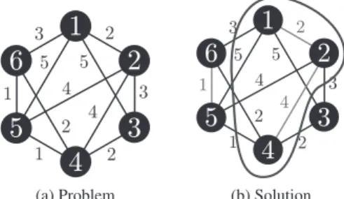
The objective of the general max-cut problem is to ob-tain a vertex set such that the total weight of the edges be-tween the vertices in the subset and the complementary sub-set becomes the largest. In the example of Fig. 3, the maxi-mum cut is 25, when{1, 2, 4}is chosen as the subset.
The max-cut problem is formulated as follows:
max1 2
i,j∈V,i<j
wi j(1−xixj), (3)
where V is a set of vertices, wi j is a weight of the edge between the vertices iand j, and xi = {−1,1} is an
indi-cator that represents the vertex i belongs to the subset or not. Here, our objective is to convert the max-cut prob-lem represented by Eq. (3) to the energy minimization of the Ising model in Eq. (2). By comparing these equations, they become equivalent when we associate the variables as
Ji j =−wi j,σi=xi, andhi=0. The spin corresponds to the
cut, and the minimum energy of the Ising model gives the maximum cut.
2.2.2 Mapping
In the mapping step, according to the formulation obtained in the previous step, parameters (interactions and biases) are assigned to the hardware Ising model. This process is called “embedding” in[14]. In general, both the formulated prob-lem and the structure of the hardware Ising model can be treated as graphs. The formulated problem can be repre-sented as a graphG=(V,E), whereVis a set of vertices that represents logical variables{σi}andEis a set of edges that
represents interactions{Ji j}. We can also obtain the graph
G′ = (V′
,E′) that represents the structure of the hardware
Ising model. In order to embedG intoG′,Gshould be a
subgraph ofG′. In this case, it is possible to simply embed
GintoG′, if the degree of allV is equal to or smaller than
that ofV′and the graphG′is sufficiently large. Otherwise, particularly when the maximum degree ofVexceeds that of
V′, a vertexσi ∈Vshould be represented using a group of
duplicated multiple vertices, called “a clone,” such that the all clones attain sufficient number of edges that realize the necessary connections of all vertices in the problem to solve, as shown in Fig. 4. Here, interactions between the vertices in a clone are determined so that the vertices tend to take the same spin value. This process is called “graph minor embedding,” which is known as an NP-hard problem[15].
The reduction of the execution time of graph minor embedding, the minimization of the number of the clones to be generated, and the determination of the optimal inter-actions between clones are currently the topics of intense researches. The detail of the general mapping algorithm is beyond the scope of this paper, so we limit ourselves to refer the algorithms proposed in[14],[15]. Similarly, the prob-lems solved in the later section are limited to be a 2D-grid torus graph structure.
2.2.3 Annealing
In this step, each spin is iteratively updated so that the lo-cal energy of the spin becomes smaller. Since a change of a spin value will affect its neighbors, the iteration is required so that the change propagates in the Ising model. The energy
Fig. 4 An example of minor embedding for a six-edge vertex to two four-edge vertices. The spinσiis duplicated using two clones,σi1andσi2.
Fig. 5 Optimization by annealing.
Algorithm 1Annealing Process of the Ising Model
1: NRF←K 2: Initializeσi 3: forn=1 toNdo
4: for alli∈Gndo
5: σi←argminHi(σi) 6: end for
7: FlipNRFspins (random flip) 8: NRF←αnNRF(αn<1) 9: end for
reduction of each spin basically decreases the total energy of the Ising model, but the reduction may stuck in a local mini-mum as shown in Fig. 5 (i). To get out of the local minimini-mum to continue to find the global minimum, temporary energy increase is necessary. In the Ising model, this is realized by a “random flip (RF),” in which a set of spins is randomly chosen and their values are flipped[9]. By the RF, the en-ergy of the entire Ising model once increases as shown in Fig. 5 (ii), but eventually decreases further as the local min-imization is repeated. This is how the global minimum is obtained (Fig. 5 (iii)).
In order to ensure convergence, “temperature schedul-ing” during the optimization process is important. The tem-perature is the metaphor of the energy input to the spins. When the temperature is high, a large number of spins are randomly flipped to increase the probability of escaping out of possible local minima. On the other hand, when the tem-perature is low, few spins are flipped and it is easy to con-verge to the steady state. To find the global minima, gradu-ally decreasing the temperature from high to low is effective. This temperature scheduling is called annealing.
Algorithm 1 shows the detailed procedure of the an-nealing. NRFis the number of spins to be randomly flipped
at a time, and K is its initial value. The following opera-tions are repeated for N times. First, a set of spins to be updated,Gn, is determined. It can be a single spin, an entire
local energy is minimized. Finally, the RF is executed and the temperature is lowered by multiplyingαn(<1) toNRF.
Note that an update of spin values can be executed in a fully parallel manner because the individual spin depends only on the adjacent spins. This is a great advantage for implementing the Ising model on highly parallel hardware architecture.
2.2.4 Interpretation
This step converts the final spin states with minimum energy after the annealing process to the solution of the original op-timization problem. It is realized just by the reverse process of the formulation. For example, in the case of the max-cut problem, the maximum cut can be obtained by calculating Eq. (3) withxi=σi.
3. Annealing Processor for the Ising Model
Recently, several specialized processors motivated by the Ising model have been proposed, such as[5],[9]–[11]. Sim-ilarly to the design in[10], our proposed annealing proces-sor is fully synthesizable, is targeting an FPGA implemen-tation, but our processor specifically aims to achieve better area efficiency. This section first describes the base archi-tecture of the proposed annealing processor with the details of its key components, and then describes the proposed two techniques to improve the area efficiency.
3.1 Base Architecture of Annealing Processor
The architecture of the proposed annealing processor is pre-sented in Fig. 6. The basic units calledIsing cells(ISC ij) are arranged in anm×nlattice form. Though the proposed architecture is not bound to a limited network topology, the target Ising model here is assumed to be in a lattice form, in which each spin has interactions with the left, right, top, and bottom adjacent spins.
Each Ising cell corresponds to a single spin and per-forms operations for spin update, which will be detailed in Sect. 3.1.1. The subscriptsiandjof each cell are indices that represent the cell location in the array. Each cellISC ij
Fig. 6 Overall architecture of the proposed annealing processor. It con-sists of a controller and a 2D-array of Ising cells (ISCs), each of which is connected to the adjacentISCs with interactionsJ.
is connected with its neighbors: left ISC i(j-1), right
ISC i(j+1), top ISC (i-1)j, and bottom ISC (i+1)j.
Interaction weights between cells are stored in the register
J ijk. For the index variablek, “v” represents the vertical interaction weights Ji jv betweenISC ijandISC (i+1)j, and “h” represents the horizontal interaction weightsJi jh
be-tweenISC ijandISC i(j+1).
All the registers for the variables Ji jk,σi j, andhi j (the
last two are inside the Ising cell) form independent scan chains for initialization and result output. Note that the scan chains are not depicted in the figure for clarity. A controller module changes operation mode of the processor, to con-trol I/O and annealing behavior, which will be described in Sect. 3.1.3.
The annealing processor is fully synthesizable, and hence it can easily be implemented on an FPGA. Although the example architecture in Fig. 6 is a simple 2-D array structure, we can configure the processor to fit various prob-lems by changing the number of connections between spins or adopting torus structure. A synthesized instance of the annealing processor with a certain configuration can be ap-plicable to solve various problems without resynthesizing the instance as long as the numbers of spins and connec-tions do not exceed its capacity. When solving the other problems, only an initialization of the registers that are stor-ing the variables Ji jk, σi j, andhi j are required, which can
be carried out in a very short time. However, if we want to solve the problems that do not fit the instance, resynthesis and reconfiguration of the FPGA are required.
3.1.1 Ising Cell
The Ising cell,ISC ij, holds the corresponding spin value
σi jin the registerσ ijand the biashi jinh ij. It performs
local energy minimization through the spin update opera-tion. The internal structure of the cell is shown in Fig. 7. The inputs of the cell are the adjacent spin values, σ(i-1)j,
σ (i+1)j, σi(j-1), and σ i(j+1), and the
interac-tion weights to the adjacent cells,J (i-1)jv,J (i+1)jv,
J i(j-1)h, andJ i(j+1)h. According to Eq. (1), the Ising cell calculates the next spin direction and updates its spin under the control of the update signalupd ijand the flip signalfp ij.
The Ising cell works as follows. The spin determina-tion moduleSpin Detdetermines the spin values detso
Fig. 8 Operation flow of the proposed annealing processor to solve a problem.
that the local energy is minimized. The multiplexerMUX1
determines whether to update the spin or not, by select-ing the output ofSpin Det or the current state. Then the multiplexerMUX2determines whether the spin is flipped or not according to the flip signalfp ij. If fp ij = 1, the flipped (multiplied by−1) spin value is selected, otherwise, the original value is selected. Finally, the output of the mul-tiplexer is stored to the registerσij, which is the final
out-put of this module.
3.1.2 Spin Determination Module
This module is inside the Ising cell and calculates the spin value byσi=argminHi(σi). From Eq. (1), the local energy Hican be calculated by
Hi=− ⎛ ⎜ ⎜ ⎜ ⎜ ⎜ ⎜ ⎝
j
Ji jσj+hi ⎞ ⎟ ⎟ ⎟ ⎟ ⎟ ⎟ ⎠
σi=−sum×σi. (4)
This means thatσican be determined just from the sign of
the value, i.e., ifsum>0,σi= +1, ifsum<0,σi=−1.
3.1.3 Controller
The controller controls the operation mode of the annealing processor according to the operation flow in Fig. 8. In the “Input Data” phase, bit stream for the problem is shift-in to initialize the registers ofJi jk andhi j using the scan chains. The initial values of the spinsσi jare also loaded. The
shift-inputs are executed in parallel usingm×n clocks, which is equal to the number of the spins. Then in the “Update Spin” phase, the spin update is repeated forN times. The spin update takes one clock cycle, and thus this phase uses
Nclocks in total. After the update phase, all spin values are read out via the scan chain. This operation also needsm×n
clocks, which is the same as the input operation.
In addition to the mode control, the controller also con-trols the spin update signals upd ij and the flip signals
fp ijto emulate the annealing behavior during the “Update Spin” phase. These operations are performed by “Update controller” and “Flip controller” modules, respectively.
3.2 Methods for Improving Area-Efficiency
In order to simulate the probabilistic annealing behavior of the Ising model, random numbers are required for two pur-poses: to determine of the spin value when the interactions are “balanced,” and to realize the random flip to increase energy temporally to avoid local optima. However, ran-dom number generators (RNGs) consume large hardware resources having significant impact on the area efficiency. In this work, the following two novel annealing methods with-out using RNGs are proposed.
3.2.1 RNG-Less Determination of Balanced Spins
The spin determination moduleSpin Detcalculates Eq. (4) to determine a spin value. If the interactions are balanced, i.e.,sumhappened to be 0, the spin can take either direction. Ideally, the spin value should be randomly determined to avoid spatial or temporal bias. Instead, we propose a simple flipping operation that approximates the random behavior without using RNGs:
⎧ ⎪ ⎪ ⎨ ⎪ ⎪ ⎩
σi← −σi ifsum=0,
σi←argminHi(σi) otherwise. (5)
With this scheme, the spin is flipped whenever the interac-tions are balanced. Otherwise, a spin value that gives lower local energy is chosen.
3.2.2 Shift-Register-Based Spin Flipper
To realize the RF on the annealing processor, the circuit that satisfies the following properties has to be considered: 1) a random pulse generator whose 0/1 probability is control-lable according to the annealing temperature, and 2) a mech-anism to deliver the generated random pulse to the flip sig-nalsfp ijfor each Ising cell. The simplest approach that satisfies the above requirements is to include an RNG and a temperature scheduler for each and every Ising cell[10]. However, it will result in an unacceptably large circuit area. Another idea is to deliver pre-calculated random sequences for all cells for every cycle, by giving up online random number generation. In this case, the distribution of the sig-nal to all the Ising cells requires long time or requires a lot of wire resources.
In this work, we resolve these issues with the proposed shift-register-based spin flipper (SRSF). The SRSF consists of the registersfp ijthat are connected in series to form a long shift register as shown in Fig. 9, or we can subdivide registers into multiple shift registers. The SRSF works as follows:
1. Load an initial bit sequenceCfp={fp 11,fp 21,· · ·,
fp mn}into the shift register withm×nclocks. 2. During each annealing, applykclocks to the shift
Fig. 9 Proposed shift-register-based spin flipper (SRSF). It consists of
fp ijregisters connected in serial like a scan chain.
3. Repeat steps 1 and 2 untilCfpbecomes all zeros.
The initial bit sequenceCfpis initialized randomly so that
0 and 1 are approximately equally contained. The random numbers here can be generated offline and in advance us-ing any algorithms. The above shift operation reduces the number of 1s in Cfp (NRF in Algorithm 1). By repeating
the shifts, it reduces the number of 1s further, which corre-sponds to the gradual decrease of the annealing temperature. By adjusting the parameterk, the speed of the temperature lowering (αnin Algorithm 1) can be controlled.
The advantage of the proposed method is the small area overhead by completely eliminate the RNGs. In addition, the initialization step (step 1) of the proposed method does not require additional clock cycles because it can be exe-cuted in parallel with the existing initializations forJ ijk,
h ij, andσij. Moreover, the proposed method can help
the Ising model from being stuck in the local optimum so-lutions having several regions of conflicting spin directions. The behavior of the SRSF causes spacial imbalance of the annealing temperature due to its shift operation, e.g., the upper area with low temperature and the lower with high temperature. Since this situation is similar to the physical phenomenon of crystalizing from the edge of the material, the proposed method is considered effective for avoiding the local optima caused by uniform global cooling.
4. Evaluation
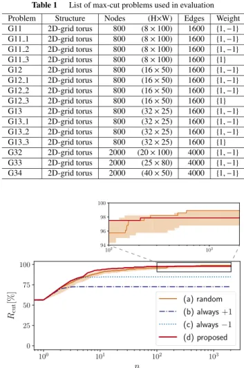
In this section, the effect of eliminating RNGs is first eval-uated, then the performance of the proposed annealing pro-cessor implemented on an FPGA is evaluated. The max-cut benchmark problems used for the evaluation of the pro-posed processor are listed in Table 1. The problems G11, G12, G13, G32, G33, and G34 are taken from G-Set bench-mark[12], while the others, Gx y, (x ∈ {11,12,13}, y ∈ {1,2,3}), are generated by “rudy”[16], which is a
genera-tor program of G-Set. Gx yhas the same graph structure as Gx, but they are different in edge weights.
4.1 Effectiveness of SRSF
4.1.1 RNG-Less Determination of Balanced Spins
In order to verify the effectiveness of the proposed RNG-less determination of balanced spins, the solution accuracy
Table 1 List of max-cut problems used in evaluation
Problem Structure Nodes (H×W) Edges Weight G11 2D-grid torus 800 (8×100) 1600 {1,−1}
G11 1 2D-grid torus 800 (8×100) 1600 {1,−1}
G11 2 2D-grid torus 800 (8×100) 1600 {1,−1}
G11 3 2D-grid torus 800 (8×100) 1600 {1}
G12 2D-grid torus 800 (16×50) 1600 {1,−1}
G12 1 2D-grid torus 800 (16×50) 1600 {1,−1}
G12 2 2D-grid torus 800 (16×50) 1600 {1,−1}
G12 3 2D-grid torus 800 (16×50) 1600 {1}
G13 2D-grid torus 800 (32×25) 1600 {1,−1}
G13 1 2D-grid torus 800 (32×25) 1600 {1,−1}
G13 2 2D-grid torus 800 (32×25) 1600 {1,−1}
G13 3 2D-grid torus 800 (32×25) 1600 {1}
G32 2D-grid torus 2000 (20×100) 4000 {1,−1}
G33 2D-grid torus 2000 (25×80) 4000 {1,−1}
G34 2D-grid torus 2000 (40×50) 4000 {1,−1}
Fig. 10 Development of solution accuracy of G11 as a function of iter-ationsn. The proposed method (d) shows the comparable accuracy to that of the random method (a).
is compared with the following methods: (a) σi← {+1,−1} (random)
(b) σi←+1 (always+1)
(c) σi← −1 (always−1)
(d) σi← −σi (proposed)
In this evaluation, a software-implemented Ising solver is used. The parameters in the spin update (Algorithm 1) are set as follows:
• Initial spin valuesσi: all 1
• Maximum number of iterations N: 3000 (G32, G33, G34), 2000 (otherwise)
• Random flips: disabled (NRF=0)
The checkerboard-like update, in which black and white cells are alternatively updated, is adopted in this experiment. Figure 10 shows the solution accuracy of the four meth-ods (a)–(d) as the function of iterations when solving G11. The solution accuracy is evaluated byRcut, which is defined
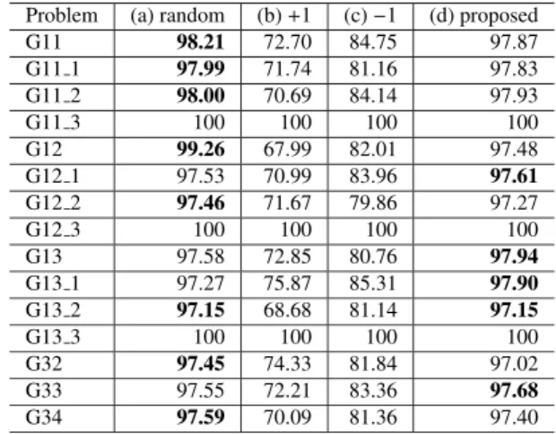
Table 2 Solution accuracies Rcut obtained by the different spin-determination methods [%]
Problem (a) random (b)+1 (c)−1 (d) proposed
G11 98.21 72.70 84.75 97.87
G11 1 97.99 71.74 81.16 97.83
G11 2 98.00 70.69 84.14 97.93
G11 3 100 100 100 100
G12 99.26 67.99 82.01 97.48
G12 1 97.53 70.99 83.96 97.61
G12 2 97.46 71.67 79.86 97.27
G12 3 100 100 100 100
G13 97.58 72.85 80.76 97.94
G13 1 97.27 75.87 85.31 97.90
G13 2 97.15 68.68 81.14 97.15
G13 3 100 100 100 100
G32 97.45 74.33 81.84 97.02
G33 97.55 72.21 83.36 97.68
G34 97.59 70.09 81.36 97.40
shaded region, and the run that achieved the best result is shown using a line. The proposed method (d) obtainsRcutof
97.9% accuracy, which is comparable to a 99.3% obtained by method (a) that uses random numbers. Table 2 shows the accuracies of final solutions when the problems in Table 1 are solved. The best result for a problem is shown in bold font. Here, all the values of (a) are the mean of 20 runs as (a) includes random process, while those of (b), (c), and (d) are the result of one run as those methods are deterministic. The proposed method (d) obtained equal or very close solution to the random flipping. There is no noticeable difference in the solution accuracies between the problems of different sizes. Hence, the proposed method is considered effective for solving the max-cut problems evaluated. The methods (b) and (c), which use a fixed spin value, could only obtain worse solutions. Our spin determination method works well without using resource-consuming RNGs.
4.1.2 Shift-Register-Based Spin Flipper
In order to verify the effectiveness of the SRSF, solu-tion accuracy is compared with the convensolu-tional flipping method that uses a random number generator. A software-implemented Ising solver and a logic simulator of Ver-ilog HDL are used for the conventional and the proposed method, respectively. The parameters in the spin update are set as follows:
• Initial spin valuesσi: random
• Maximum number of iterations N: 3000 (G32, G33, G34), 2000 (otherwise)
• Random flip: K = 0.5×(spin size) andαn = 0.996
(G32, G33, G34),αn =0.993 (otherwise) for the
con-ventional method, and decrement NRF by 1 for each
iteration for the proposed method. αnis determined so
thatNRFbecomes 0 at about the same time as the
pro-posed method.
In both methods, the checkerboard-like update is adopted, and the optimizations are run for 100 times to obtain av-eraged performance. Figure 11 compares how the solution
Fig. 11 Development of solution accuracy of G11 as a function of itera-tionsn. The proposed SRSF (b) shows the comparable accuracy to that of the random method (a).
Table 3 Solution accuraciesRcutof spin-flipping methods [%] Problem (a) random (b) SRSF
mean max mean max
G11 98.73 100 98.48 100
G11 1 98.79 100 98.44 100
G11 2 98.68 99.66 98.16 99.31
G11 3 98.69 100 99.99 100
G12 98.75 100 98.68 99.64 G12 1 98.36 99.66 97.89 98.98
G12 2 98.46 100 97.98 99.32
G12 3 98.74 100 100 100
G13 98.46 99.66 97.10 98.63 G13 1 98.44 99.65 97.55 99.30
G13 2 98.50 100 97.33 98.93
G13 3 99.74 100 99.60 100
G32 98.64 99.29 98.16 99.01
G33 95.70 99.42 97.30 98.41
G34 98.79 99.28 98.46 99.42
accruracies changed as a function of iteration count. Since the initial spin values are randomly determined, the upper and the lower bounds of the results are shown as a shaded region, and the run that achieved the best result is shown us-ing a line. Both methods obtain optimal solution almost at the same iteration counts. Table 3 shows the mean and the best accuracies, in which bold font indicates better results between the corresponding columns. Again, the proposed SRSF achieved very close solution accuracy to the conven-tional method. By using proposed SRSF, good optimiza-tion results are expected without using resource-consuming RNGs.
4.2 Evaluation of Hardware-Implemented Annealing Pro-cessor
The proposed annealing processor is implemented on an FPGA to evaluate its circuit area and speed to solve max-cut problems. The spin valueσis expressed using 1 bit (0 for “+1” and 1 for “−1”) and both the interaction weight J
Table 4 FPGA resource usage of the annealing processor with 800 spins (G11)
Module Slices LUTs Registers
Cell array 10,975 (21.2%) 19,190 (9.3%) 5,600 (2.7%)
Ising cell (avg.) 13.7 24.0 7.0
Controller 229 (0.4%) 80 (0.0%) 848 (0.4%)
Flip controller 202 (0.4%) 2 (0.0%) 801 (0.4%)
Others 27 (0.0%) 78 (0.0%) 47 (0.0%)
Overall 11,204 (21.3%) 19,270 (9.3%) 6448 (3.1%)
Table 5 FPGA resource usage of the annealing processor with 2000 spins (G32)
Module Slices LUTs Registers
Cell array 34,185 (65.94%) 52,010 (25.08%) 14,000 (6.75%)
Ising cell (avg.) 17.1 26.0 7.0
Controller 527 (1.0%) 79 (0.0%) 2046 (1.0%)
Flip controller 502 (1.0%) 3 (0.0%) 2001 (1.0%)
Others 25 (0.0%) 76 (0.0%) 45 (0.0%)
Overall 34,712 (67.0%) 52,089 (25.1%) 16,046 (7.7%)
4.2.1 Circuit Area and Maximum Delay
The proposed annealing processor was written in Verilog HDL and synthesized/implemented by Xilinx ISE Design Suite 14.7 for a target FPGA, Xilinx Virtex5 XC5VLX330T. Tables 4 and 5 show the breakdown of the resource usage after synthesis for the problems of G11 with 800 nodes and for G32 with 2000 nodes, respectively. Synthesis results for the other problems are omitted since the resource usages are determined by the number of nodes. The percentages to the total resources are also shown in the parentheses. The maxi-mum delays of the designs for all the problems are less than 5.0 ns, meaning that the proposed processor can operate at 200 MHz. As shown in Table 4, the proposed SRSF used 202 slices, which is much smaller than the array of the Ising cells. By eliminating the RNGs, the area efficiency of the annealing processor has been greatly improved. According to Tables 4 and 5, the resource usage of slices and LUTs in-creases linearly to the number of nodes, indicating that the proposed annealing processor is scalable as long as the max-imum number of edges is bounded to a small number. 4.2.2 Speed and Accuracy
In order to evaluate the efficiency of solving optimization problem on an FPGA, the synthesized netlist is implemented on the same FPGA board, and a PC with Intel Core i7-6700K @4.00GHz is used as a host. The FPGA board and the PC are connected via PCI Express, and the input/output data are transferred by using a DDR2 memory on the FPGA board. A control program on the host PC written in C lan-guage controls the following execution flow:
(a) PC converts a problem to the Ising model (Mapping) (b) PC writes data to DDR2 memory on FPGA board (c) FPGA executes annealing of the Ising model (d) PC reads data from DDR2 memory on FPGA board The process (c) includes all the operations on the FPGA,
Table 6 Runtime of the proposed annealing processor for solving max-cut problems (G11 and G32)
Process Time (G11) Time (G32)
(a) Mapping on PC 690µs 980µs
(b) Write data from PC to FPGA board 80µs 80µs
(c) Annealing on FPGA 80µs 100µs
(d) Read data from FPGA board to PC 70µs 70µs
Total 0.92 ms 1.23 ms
which are data input/output between the DDR2 memory and the FPGA and the spin update operation as shown in Fig. 8. The execution time of each step to solve G11 and G32 is summarized in Table 6. Numbers of iterations in the spin update areN = 2000 for G11 andN =3000 for G32. We omit the runtime of the other problems because their run-times are completely equal to those with the same number of spins. The processing time to solve a single problem with the proposed annealing processor only takes about 1 ms in total, including communications between PC.
We also compare the execution time with other max-cut solvers: (A) SW Ising: software-implemented Ising model solver, (B) CPLEX: mixed-integer programming (MIP) solver[17], and (C) SG3: existing fastest heuristic algorithm for max-cut solver[1]. Here, (A) is the same as the software Ising solver in Sect. 4.1.2. For the experiments, SW Ising and SG3 were run on a PC with Intel Xeon E5-1650 @3.5 GHz, and CPLEX was run using 32 threads on a PC with Intel Xeon E5 @2.6 GHz. SW Ising and SG3 were written in C++language.
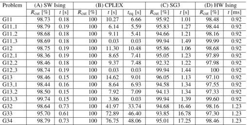
Figures 12, 13, and Table 7 show the comparison of the solving time by the proposed FPGA-based annealing pro-cessor (D) and the other software solvers (A)–(C). Note that
tin Table 7 means runtime of the algorithms andteqis the
time required for CPLEX to obtain a solution with an equal accuracy to that of HW Ising. As shown in Fig. 12, HW Ising by the proposed processor is 2.0×10²times faster than
Table 7 Solution accuracyRcutand runtime of four algorithms
Problem (A) SW Ising (B) CPLEX (C) SG3 (D) HW Ising
Rcut[%] t[s] Rcut[%] t[s] teq[s] Rcut[%] t[s] Rcut[%] t[ms]
G11 98.73 0.18 100 10.27 6.66 95.92 1.01 98.48 0.92
G11 1 98.79 0.19 100 6.14 5.59 95.83 1.27 98.44 0.92
G11 2 98.68 0.18 100 9.11 5.41 94.66 1.21 98.16 0.92
G11 3 98.69 0.18 100 0.03 0.03 99.94 1.49 99.99 0.92
G12 98.75 0.19 100 11.30 10.48 95.86 1.06 98.68 0.92
G12 1 98.36 0.19 100 8.65 7.41 95.05 1.23 97.89 0.92
G12 2 98.46 0.18 100 9.37 7.48 92.32 1.22 97.98 0.92
G12 3 98.74 0.19 100 0.03 0.03 99.94 1.44 100 0.92
G13 98.46 0.15 100 14.62 9.01 96.05 1.13 97.10 0.92
G13 1 98.44 0.16 100 8.64 6.93 94.58 1.34 97.55 0.92
G13 2 98.50 0.15 100 7.92 7.09 94.13 1.34 97.33 0.92
G13 3 99.74 0.15 100 3.86 0.03 99.94 1.39 99.60 0.92
G32 98.64 0.73 100 41.97 33.74 94.68 16.46 98.16 1.23
G33 95.70 0.61 100 72.89 46.40 93.85 16.78 97.30 1.23
G34 98.79 0.73 100 76.75 48.06 95.01 17.25 98.46 1.23
Fig. 12 Solution accuracy of G11 as a function of runtime.
Fig. 13 Solution accuracy of G32 as a function of runtime.
the other hand, CPLEX obtained the optimal solution but it took much longer time to the other solvers. When the calcu-lation time of CPLEX is compared to the HW Ising at a same accuracy, HW Ising is faster than CPLEX by 7.2×10³.
Fig-ure 13 also shows similar trend. HW Ising is 5.9×10²times
faster than SW Ising and 2.7×10⁴times faster than CPLEX.
The results are similar for the other problems except G11 3, G12 3, G13 3, for which, however, our HW Ising is still 10 times faster. This result shows that the proposed architec-ture is suitable to obtain quasi optimal solution with a very short time.
5. Conclusion
This paper proposed an area-efficient highly parallel
anneal-ing processor that utilizes no random number generator. The proposed processor is based on the Ising model, and fully synthesizable, scalable, and configurable for the problems to solve. In order to eliminate random number generators, a spin flipping scheme for balanced spin and a shift-register-based spin flipping scheme in the annealing are introduced. Through an implementation of the proposed architecture on an FPGA and evaluation solving max-cut problems, our an-nealing processor achieved 10–104times speedup compared
with conventional optimization algorithms to obtain the so-lution of equal accuracy.
Acknowledgments
This work was partially supported by JSPS KAKENHI Grant No. 26280014 and 17H01713. This work was also supported by VLSI Design and Education Center (VDEC), the University of Tokyo in collaboration with Mentor Graphics, Inc.
References
[1] S. Kahruman, E. Kolotoglu, S. Butenko, and I.V. Hicks, “On greedy construction heuristics for the MAX-CUT problem,” International Journal of Computational Science and Engineering, vol.3, no.3, pp.211–218, 2007.
[2] G.A. Kochenberger, J.-K. Hao, Z. L¨u, H. Wang, and F. Glover, “Solving large scale max cut problems via tabu search,” Journal of Heuristics, vol.19, no.4, pp.565–571, 2013.
[3] L. Grippo, L. Palagi, M. Piacentini, V. Piccialli, and G. Rinaldi, “SpeeDP: an algorithm to compute SDP bounds for very large max-cut instances,” Mathematical Programming, vol.136, no.2, pp.353–373, 2012.
[4] H. Nishimori, Statistical Physics of Spin Glasses and Information Processing, Oxford University Press, 2001.
[5] D-Wave. http://www.dwavesys.com/.
[6] T. Kadowaki and H. Nishimori, “Quantum annealing in the trans-verse ising model,” Physical Review E, vol.58, no.5, pp.5355–5363, 1998.
[8] V.S. Denchev, S. Boixo, S.V. Isakov, N. Ding, R. Babbush, V. Smelyanskiy, J. Martinis, and H. Neven, “What is the computational value of finite-range tunneling?,” Physical Review X, vol.6, no.3, 2016.
[9] M. Yamaoka, C. Yoshimura, M. Hayashi, T. Okuyama, H. Aoki, and H. Mizuno, “20k-spin ising chip for combinational optimiza-tion problem with CMOS annealing,” Digest of Technical Papers of IEEE International Solid-State Circuits Conference (ISSCC), p.24.3, 2015.
[10] C. Yoshimura, M. Hayashi, T. Okuyama, and M. Yamaoka, “Imple-mentation and evaluation of FPGA-based annealing processor for ising model by use of resource sharing,” International Journal of Networking and Computing, vol.7, no.2, pp.154–172, 2017. [11] K. Someya, R. Ono, and T. Kawahara, “Novel ising model using
di-mension-control for high-speed solver for ising machines,” Proceed-ings of 14th IEEE International New Circuits and Systems Confer-ence (NEWCAS), 2016.
[12] G-Set. http://web.stanford.edu/˜yyye/yyye/Gset/.
[13] A. Lucas, “Ising formulations of many NP problems,” Frontiers in Physics, vol.2, no.5, pp.1–15, 2014.
[14] A. Zaribafiyan, D.J.J. Marchand, and S.S.C. Rezaei, “Systematic and deterministic graph minor embedding for cartesian products of graphs,” Quantum Information Processing, vol.16, no.5, 2017. [15] J. Cai, W.G. Macready, and A. Roy, “A practical heuristic for finding
graph minors,” 2014. arXiv:1406.2741.
[16] C. Helmberg and F. Rendl, “A spectral bundle method for semidef-inite programming,” SIAM Journal on Optimization, vol.10, no.3, pp.673–696, Jan. 2000.
[17] IBM, “IBM ILOG CPLEX Optimization Studio V12.6.2 documen-tation.”
Hidenori Gyoten recieved B.E. degree in Electrical and Electronic Engineering from Kyoto University in 2016. He is a master course student at Department of Communications and Computer Engineering, Kyoto University.
Masayuki Hiromoto received B.E. de-gree in Electrical and Electronic Engineering and M.Sc. and Ph.D. degrees in Communica-tions and Computer Engineering from Kyoto University in 2006, 2007, and 2009 respectively. He was a JSPS research fellow from 2009 to 2010, and with Panasonic Corp. from 2010 to 2013. In 2013, he joined the Graduate School of Informatics, Kyoto University, where he is cur-rently a senior lecturer. His research interests include VLSI design methodology, image pro-cessing and pattern recognition. He is a member of IEEE and IPSJ.