Optimization Design of
Carburizing and Quenching
Process in Consideration of
Transformation Plasticity Mechanism
変態塑性のメカニズムを考慮した浸炭焼き入れ
プロセスの最適化設計
Shan Miao
Table of Contents
Abstract ... I
Acknowledgments ... II
Chapter 1 Introduction ... 1
1.1 Carburizing and quenching ... 1
1.1.1 Carburization ... 2
1.1.2 Quenching ... 4
1.1.3 Residual stress in carburizing and quenching ... 5
1.1.4 Retained austenite in carburizing and quenching ... 5
1.1.5 Distortion in carburizing and quenching ... 6
1.1.6 Fatigue strength ... 7
1.2 Transformation plasticity behavior ... 8
1.3 Simulation in carburizing and quenching ... 12
1.4 Optimization design ... 13
1.4.1 DOE full factorial ... 13
1.4.2 Orthogonal design ... 14
1.4.3 Topology optimization ... 14
1.4.4 Genetic algorithm ... 15
1.5 Purpose and composition of this thesis ... 17
References ... 20
Chapter 2 Mechanism of transformation plasticity ... 30
2.1 Introduction ... 30
2.2 Theory of transformation plasticity... 31
2.2.1 Constitutive Equation ... 31
2.2.2 Austenite transformation plasticity behavior ... 34
2.3 Experimental procedure ... 34
2.4 Results ... 36
2.4.1 Transformation plasticity during cooling ... 36
2.4.2 Austenite transformation plasticity coefficient ... 41
2.4.3 Mechanical properties and parameters of materials ... 44
2.5 Concluding remarks ... 46
References ... 47
Chapter 3 Verification of material properties by simulation of
axisymmetric model ... 49
3.1 Introduction of COSMAP ... 49
3.2 Basic theory of transformation and thermodynamics ... 50
3.2.1 Mixture Rule ... 50
3.2.2 Heat Conduction Equations ... 51
3.2.3 Diffusion equation ... 51
3.2.4 Hardening rule ... 52
3.2.6 Rate form of stress-strain relation ... 54
3.2.7 Austenite transformation plasticity ... 56
3.3 Effect of transformation plasticity on simulation of quenching ... 58
3.4 Effect of transformation plasticity on simulation ... 61
3.4.1 Carbon Diffusion and Distribution ... 62
3.4.2 Hardness Distribution ... 63
3.4.3 Results of Residual Stresses ... 64
3.4.4 Distortion of the Cylinder after Quenching ... 65
3.5 Effect of quenching oil on heat treatment results ... 66
3.6 Concluding remarks ... 71
References ... 72
Chapter 4 Optimization and verification of carburizing and
quenching process of gear ... 74
4.1 Introduction ... 74
4.2 Modelling and conditions ... 75
4.3 Optimized design ... 76
4.4 Process optimization by orthogonal experimental ... 79
4.5 Results of experiment and simulation ... 81
4.5.1 Distortion of the Gear after Quenching ... 81
4.5.2 Hardness Distribution ... 83
4.6 Conclusion remarks ... 84
References ... 85
Chapter 5 Verification of fatigue strength by optimum process ... 88
5.1 Introduction ... 88
5.2 Experimental procedure ... 89
5.2.1 Heat treatment process ... 89
5.2.2 Material and preparation specimens ... 89
5.3 Results and discussion ... 91
5.3.1 Microstructure ... 91
5.3.2 Analysis of component distribution ... 94
5.3.3 Surface Hardness ... 100
5.3.4 Residual stress ... 101
5.3.5 Domain size ... 102
5.3.6 Fatigue behavior ... 104
5.3.7 Fatigue crack growth ... 106
5.3.8 Fracture morphology ... 110
5.4 Conclusion remarks ... 111
References ... 113
Chapter 6 Summary ... 116
Abstract
Acknowledgments
I would like to express my sincere appreciations to Prof. Dongying Ju, for taking me as his student and giving me the opportunity to pursue the Ph.D. degree at Saitama Institute of Technology. I want to express my sincere thanks for his support, encouragement and guidance throughout my study. Without his support I could not have achieved so much.
I would like to express thanks to Prof. Masaya Uchida, Prof. Michiharu Narazaki, Prof. Hiroki Ishizaki and Prof. Seizo Furuya for sparing time from their busy schedules in reviewing my dissertation and their advisable comments for revising the paper. Without their help, I couldn’t have understood the research deeply.
I would like to thank Prof. Masaya Uchida who gave me many valuable suggestions and help in microstructure measurement.
I would like to show gratefulness to the continuous support from the High-Tech Research Center and Open Research Center at the Saitama Institute of Technology.
Special thanks to Mr. R. Mukai and Mr. K. Nakajima of Saitama Institute of Technology for his enormous help in machining various specimens and tools.
I also thank previous and current Ju Lab members at Saitama Institute of Technology: Dr. H. Y. Zhao, Dr. J. G. Wang, Dr. X. H. Deng, Dr. B. Han, Dr. D. Xu, Mr. Y. R. Man and Miss W. Cai for their frequent and fruitful discussions.
Chapter 1 Introduction
With the progress of science and technology, the automobile is developing gradually in the direction of lightweight and low energy consumption [1, 2]. Therefore, electric vehicles are receiving more and more attention because of their environmentally friendly and energy-efficient. However, with the rapid development of the electric vehicle industry, it puts forward higher request to the load capacity and economy of the gearing which is the core equipment of mechanical transmission system. At present, the carburizing and quenching has been widely used for surface hardening because the hard surface gear has the advantages of thigh strength, small volume and light weight. However, distortion and fatigue properties after heat treatment are two problems commonly occurred in the production and application of transmission gears. Simultaneous preparation of gear with smaller variants and good fatigue properties is one of the major topics at present. On the other hand, transformation plasticity behavior is found to have a significant effect on the deformation and residual stress during the phase transformation of the gear.
1.1 Carburizing and quenching
Carburizing and quenching process is often used in industry as a method of surface hardening technique to obtain improved mechanical properties and fatigue strength of mechanical components, such as gears, shafts and so on [3-5]. Carburizing and quenching is usually carried out on low carbon steels, which relies on high hardness surface layer to provide strength and wear resistance that cannot obtainable from the core metal [6-8].
when it is used as a part after finishing the final processing, it is desirable to have high intensity, high fatigue strength and high reliability. Therefore, carburizing and quenching technology gives the material a soft and easy to process characteristic before processing and high strength in the final process after parts processing to have superior lifetime and high reliability. In the future, carburizing and quenching technology is indispensable in the industrial field in order to satisfy the needs for environmentally friendly and inexpensive steel.
Fig. 1-1 Mechanical processing of gears
The initial carbon content in most steels used for carburizing and quenching is the range of 0.10% to 0.30%. Steel 20MnCrS5 is one of the most important metallic materials used for many applications including mechanical structural parts due to its characteristics and diversity of functions, and one of the technologies that brings various characteristics and functions of steel [12, 13]. In the automotive industry, carburized 20MnCrS5 steel is typically used for differential ring gears, camshafts and transmission gears for its excellent carburizing response with good hardenability for most section sizes [12, 14, 15]. The carburizing and quenching process includes two parts, carburization and quenching.
1.1.1 Carburization
Carburization is a case hardening process in which carbon is diffused into the surface layers of a steel part at a temperature below its melting point and above its A3
critical temperature, at which austenite, with its high solubility for carbon, is the stable crystal structure [16, 17]. It is the addition of carbon at the surface of low-carbon steels within the austenitic region temperature, which is between 850℃ and 950℃ for carburizing steels generally. Hardening is accomplished when the subsequent
high-Processing Cutting and polishing
F o rgi n g m at e ria ls Cu st om er Carburizing
carbon surface layer is quenched to form martensite so that a high-carbon martensitic case with good wear and fatigue resistance is superimposed on a tough, low carbon steel core as shown in Fig. 1-2 [18].
Fig. 1-2 Carbon diffusion process in carburizing and quenching
In order to ensure a satisfactory and reliable intensity and fatigue strength of carburized parts – it is imperative to understand the mechanism of carbon transfer and to accurately predict carbon concentration profile and case depth during the carburizing and quenching process. Successful carburizing performance depends on the effective control of the three principal variables: temperature, time and the carburizing atmosphere. Some research has been performed to investigate the effect of these process parameters on the carburizing kinetic coefficients, i.e. the mass transfer coefficient and carbon diffusivity in steel [19-24]. The mass transfer coefficient has been reported to be a complex function of the atmosphere gas composition, carburizing potential, temperature and surface carbon content. The coefficient of carbon diffusion in austenite is another parameter determining the rate of carbon transport, which is strongly influenced by the carburizing temperature and carbon concentration in steel [25]. Although the mechanism of mass transport in carburizing appears to be known and understood, the results of the current industrial carburizing practices show that the carbon concentration profiles and case depths often deviate from those of the predicted ones.
The carburizing potential in the furnace is determined by the atmosphere gas composition. Accurate carbon potential calculation requires not only adequate
Low carbon steel High Carbon Concentration Low Carbon Concentration C C C C C C C C Surface Inside
measurement of the gas constituents (CO, CH4, CO2 and H2O) in the furnace but also
representative sampling locations where the constituents are analyzed. Since surface carbon concentration and flux of carbon atoms from the atmosphere to the steel surface change with time, maintaining a constant atmosphere carbon potential during single stage carburization requires continuous adjustment of the set point until the parts meet the required specification. An increase in the carburizing temperature increases the rate of mass transfer both in the furnace atmosphere and steel. It also promotes excessive austenite grain growth and deteriorates the furnace condition. The effect of time on case depth is interdependent with the carburizing temperature and is often estimated by using the Harris equation [26].
1.1.2 Quenching
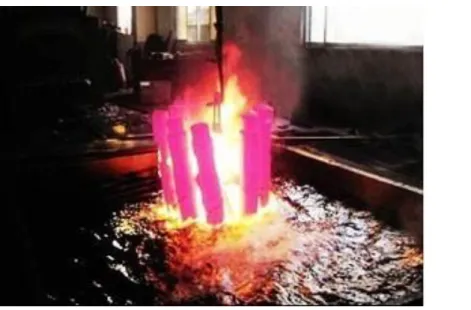
Fig. 1-3 An example of quenching
1.1.3 Residual stress in carburizing and quenching
The residual stress may be defined as the self-equilibrating internal or locked-in stress remaining within a body with no applied (external) force, external constraint, or temperature gradient. These residual stresses must be balanced near the surface or in the body of a material, i.e., negative (compressive) in one region and positive (tensile) in another. Residual stresses may be generated by variations in stress, temperature, and chemical species within the body. In heat-treated materials, residual stresses may be generated by a variation in temperature (thermal gradient) alone or a combination with a change in chemical species.
When a steel part is quenched from the austenitizing temperature to room temperature, residual stresses are produced due to a combination of a thermal gradient and a phase transformation-induced volume expansion: austenite transforms to martensite or other products [31].
1.1.4 Retained austenite in carburizing and quenching
High carbon and carburized low carbon steels such as carburized 20MnCrS5 steel always contain retained austenite to varying degrees in the as-hardened and also in the quenching [32].
boundaries, but is unstable below these temperatures. On quenching from the austenite-stable area, austenite transforms to martensite which usually forms at a characteristic temperature named MS and continues to form with decreasing temperature until Mf, the
temperature of 100% transformation is reached. However, in many hardenable steels such as plain carbon and low alloy steels with carbon contents more than 0.5%, the Mf
temperature is below room temperature, so that a considerable quantity of untransformed austenite may be retained at room temperature in these steels [33-36].
The quantity of retained austenite depends on the austenitizing temperature, chemical composition, especially the carbon content, cooling rate and final temperature of the quenching process [34]. As to the presence of retained austenite, Grosch and Schwarz point out that the case-microstructure of carburized steels always consists of plate martensite and retained austenite for case-carbon contents higher than 0.6%. The amount of retained austenite is mainly determined by the carbon content: for steels of the same carbon content, the effect of the content of the other alloying elements is also noticeable [36]. The martensite finish temperature, Mf of plain carbon and low alloy
steels with carbon contents more than about 0.5%, is below room temperature. That is why austenite that contains more than 0.5% carbon in solid solution does not completely transform into martensite when quenched to room temperature [36].
1.1.5 Distortion in carburizing and quenching
thermal strain / transformation strain and has a great influence on the deformation after the heat treatment, both heat treatment experiment and heat treatment simulation analysis need to analysis this behavior in detail.
1.1.6 Fatigue strength
Since failure caused by repeated loading accounts for at least half of all mechanical failures, the fatigue performance is prime importance for the materials which are subject to cyclic loading [42]. Carburizing and quenching process is widely used in industry, as a method of surface hardening technology to obtain improved mechanical properties and fatigue strength of mechanical components, such as gears, shafts and so on [3, 43]. The main advantages of carburizing are that they can achieve high surface hardness, compressive residual stress and good toughness at the core, which can effectively improve the surface strength, wear resistance and fatigue strength of the steel [44].
It is well known that many performances can affect the fatigue resistance of carburized parts. One of the important performances is the distribution of residual stresses. The compressive residual stresses counteract the applied tensile stresses and therefore improve the fatigue performance. The ideal hardness distribution shifts the failure initiation point transfer from the core to the surface. Therefore, in order to obtain maximum gain in fatigue resistance, the hardness distribution should be kept in a certain range depending on the thickness and size of the specimen [45]. Core microstructure is also one of these performances. Lower carbon content of core increases the fatigue resistance, particularly due to the enlarged compressive residual stresses at the surface, compared with the cases of higher carbon content [46]. The refinement of austenitic grain size is also one of these performances, which results in a fine martensitic structure and/or reduced size and density of micro cracks in the structure produce better fatigue resistance [47, 48].
numerical analysis technology and computers, simulations of phase transformation and thermal / mechanical behavior in the quenching process were conducted simulation.
Many factors such as carburizing time and temperature during the various stages of a carburizing process affect the performance above [49]. It is necessary to determine the relationship between the carburizing process factors and the material performances. It is very important to select the proper carburizing and quenching condition but it is difficult to decide the compromise between maximum hardness and minimum distortion. Computer simulation is very useful for the determination of the quenching condition to obtain the optimum quality. The application of “metallo-thermo-mechanical” theory is capable of describing the interaction among temperature field, stress/deformation field and microstructure changes in quenching.
It is expected that various problems in the heat treatment process will be elucidated by the technology. However, most simulation codes so far focused on phase transformation, residual stress and deformation that occurred inside the material, the effect of the heat transfer behavior of the coolant used for quenching on the material there are not enough studies that take into consideration. Also, with respect to complicated geometric models such as gears, some simulation is performed by cutting out a part, and almost no simulation of the whole model is performed. Measurement of residual stress on the part surface by X-ray diffraction is the mainstream for evaluating residual stress. For the measurement of the internal residual stress in a component having a plurality of metallic structures such as a quenched material, it may have significant significance in the strength evaluation of the part, and development of a new residual stress evaluation technique is expected there.
1.2 Transformation plasticity behavior
improve the mechanical properties of steels and products. The properties of metallic materials can be changed during heat treatment such as welding or quenching process. In these processes, the material is exposed to high temperature or heat generated during the processing. In this case, if the temperature is not uniformly distributed, thermal stress will generate or the residual stress existence in materials, the shape of materials will change by plastic deformation [3, 50]. During heat treatment, the relations between temperature, stress/strain and microstructure called coupling effects are very complex. In particular, transformation plasticity behavior with the nucleation and growth during phase transformation is necessary to know in detail in both experiment and simulation for which give a significant impact on the relationship of stress-strain of inelastic in the heat treatment process. The research about transformation plasticity has been conducted and theoretically studied by now [51]. For instance, experiment for identification of transformation plasticity of pearlite transformation by the tensile test is being carried out. However, few kinds of materials are identified, because the experiments must be repeated under various loads for research on transformation plasticity. The condition of the experiments requires rapid cooling for transformation plasticity of bainite transformation and martensitic transformation, therefore, rare attention is being paid to the experiment research.
two basic characteristics: first, it occurs with organizational transformation. Second, the applied stress is not required to reach or even the weak phase yield strength.
Lambers experimentally studied the role of austenitization and plastic pre-deformation on isothermal bainite and martensitic transformation behavior of low alloy steel. According to the test results, the austenitization conditions strongly affect the isothermal bainitic and martensitic transformations and the plastic pre-deformations at high austenitization temperature accelerated the isothermal phase transformation, but at low austenitization temperature the acceleration was not happened [52, 53]. The effect of austenite grain size on the kinetics of upper and lower bainite transformation of low alloy steel was reported by Lee et al. [54]. The transformation rate of upper bainite increased with reduction of austenite grain size and the transformation rate of lower bainite is independent of austenite grain size. The effect of stress and strain on martensitic transformation plasticity was investigated by Liu with tensile and compressive loading system. Here, the transformation plasticity coefficient increases with increases in applied stress, but when the applied stress reached to the yield stress, the transformation plasticity coefficient is constant even the applied stress increased [55]. The effect of compressive deformation of austenite on the isothermal bainite/ferrite transformation showed that the increases of deformation caused reduction on the value of ferrite bainite transformation [56]. The stress-dependent phase transformation and transformation induced plasticity were tested and modelled with simple experiments such as uniaxial tensile or torsional tests, and using the obtained results under constant temperature and loading, the material behavior under time-dependent conditions can be tested [57].
At present, there are two main explanation mechanisms for transformation plasticity: Greenwood-Johnson mechanism and Magee mechanism [58, 59].
during the phase transformation, and the calculation is derived based on the plastic flow theory and the yield criterion. Transformation plasticity is due to standard, dislocation-induced plasticity at the microscopic scale in the weaker, mother-phase (that prevailing at high temperatures, with a generally much lower yield stress). Microscopic plasticity arises from the difference of specific volume between the phases coexisting during the transformation (volumetric part of the transformation strain), which generates internal stresses of sufficient magnitude to induce plasticity in the weaker one. The effect occurs even in the absence of external stress; but such a stress, when present, takes advantage of the internal “transformation-induced weakness” of the material to deform it plastically. An analytical formula for the transformation plasticity induced by phase transformation. In later research, the equations of the sum are extended to study the transformation plasticity under high stress state [60-62]. It is found that the transformation plasticity strain exhibits a non-linear change with the stress when the stress approaches the yield strength of the weak phase.
1.3 Simulation in carburizing and quenching
The thermo-mechanical behavior of materials undergoing a solid-solid phase transformation has been largely investigated experimentally and numerically. The transformation plasticity behavior under uniaxial loading have experimentally studied by many researchers with different materials [63-73]. Simon and Inoue have numerically analyzed the effect of applied tensile stress during pearlite phase transformation for the eutectoid carbon steel [65, 68-70]. Kim numerically analyzed the thermo-elastic plastic constitutive equation of Leblond, which accounts for the transformation plasticity in welding, has been carried out for finite element analysis [74-76]. The thermo-elastic free energy with the temperature-dependent material constants has been employed together with the relation of the transformation plastic flow rule between the additive decomposition of the rate of deformation and the multiplicative decomposition of the deformation gradient [76]. Furthermore, phase-field method, a computational technique, has been used to simulate the microstructure evolution during various phase transformations [77-80].
from DASSAULT SYSTEMES Company provides users with an extensive array of user subroutines that allow them to adapt Abaqus to their particular analysis requirements. In order to increase the functionality of several Abaqus capabilities, many user subroutines which they furnish an extremely powerful and flexible tool for analysis are provided.
1.4 Optimization design
The experimental design is based on probability theory and mathematical statistics, and it is a scientific method to study and deal with the relationship between multi-factor and response variables. Through the experimental design method, reasonable and effective sample points can be extracted, so that the researchers can obtain the unbiased processing effect and the estimation of the test error when performing statistical analysis on the test results, so as to make a correct and effective judgment.
The experimental design was derived from agricultural production, analyzing the different ratios of phosphorus and nitrogen fertilizers, and the effect on wheat yield, so as to find the optimal fertilization ratio to increase the yield per unit of wheat. After nearly a hundred years of development, the application design has been extended to various fields of daily life. The experimental design was originally applied only in physical experiments. After development, it has been widely used in non-physical tests. The experimental design method is also the first few have evolved into a variety of experimental design methods. The following are common test design methods.
1.4.1 DOE full factorial
levels, the reliability of the analysis can be obtained. With increasing the number of factors and the number of levels, the number of experiments required will multiply. Three factors and three levels of test design requires 27 trials. Equation 2.5 is the formula for calculating the number of full factor tests. Equation 1 is the formula for calculating the number of full factor tests.
𝑓 = 𝑛1× 𝑛2× 𝑛𝑖 × ⋯ × 𝑛𝑚 (1) Where 𝑛𝑖 is the number of levels of the i-th factor, and m is the number of factors. 1.4.2 Orthogonal design
Orthogonal test design is the main test method for researching and processing multi-factor tests. According to the principle of orthogonality, a representative test point is selected from the comprehensive test. Due to the balanced distribution of factors and levels, and uniform distribution of data points, it is widely used in various fields of daily life. The orthogonal table is a mathematical form constructed by mathematical theory and is the basic tool of orthogonal experimental design. The test results are statistically analyzed by corresponding range analysis, variance analysis and regression analysis.
1.4.3 Topology optimization
Topology optimization (TO) is a mathematical method that optimizes material layout within a given design space, for a given set of loads, boundary conditions and constraints with the goal of maximizing the performance of the system. TO is different from shape optimization and sizing optimization in the sense that the design can attain any shape within the design space, instead of dealing with predefined configurations.
The conventional TO formulation uses a finite element method (FEM) to evaluate the design performance. The design is optimized using either gradient-based mathematical programming techniques such as the optimality criteria algorithm and the method of moving asymptotes or non-gradient-based algorithms such as genetic algorithms.
level of a design process. Due to the free forms that naturally occur, the result is often difficult to manufacture. For that reason, the result emerging from TO is often fine-tuned for manufacturability. Adding constraints to the formulation in order to increase the manufacturability is an active field of research. In some cases, results from TO can be directly manufactured using additive manufacturing; TO is thus a key part of design for additive manufacturing.
1.4.4 Genetic algorithm
In 1950, Alan Turing proposed a "learning machine" which would parallel the principles of evolution [81]. Computer simulation of evolution started as early as in 1954 with the work of Nils Aall Barricelli, who was using the computer at the Institute for Advanced Study in Princeton, New Jersey [82, 83]. His 1954 publication was not widely noticed. Starting in 1957 [84], the Australian quantitative geneticist Alex Fraser published a series of papers on simulation of artificial selection of organisms with multiple loci controlling a measurable trait. From these beginnings, computer simulation of evolution by biologists became more common in the early 1960s, and the methods were described in books by Fraser and Burnell (1970) and Crosby (1973) [85]. Fraser's simulations included all of the essential elements of modern genetic algorithms. In addition, Hans-Joachim Bremermann published a series of papers in the 1960s that also adopted a population of solution to optimization problems, undergoing recombination, mutation, and selection. Bremermann's research also included the elements of modern genetic algorithms. Other noteworthy early pioneers include Richard Friedberg, George Friedman, and Michael Conrad. Many early papers are reprinted by Fogel (1998).
evolutionary programming technique of Lawrence J. Fogel, which was proposed for generating artificial intelligence. Evolutionary programming originally used finite state machines for predicting environments, and used variation and selection to optimize the predictive logics. Genetic algorithms in particular became popular through the work of John Holland in the early 1970s, and particularly his book Adaptation in Natural and Artificial Systems (1975). His work originated with studies of cellular automata, conducted by Holland and his students at the University of Michigan. Holland introduced a formalized framework for predicting the quality of the next generation, known as Holland's Schema Theorem. Research in GAs remained largely theoretical until the mid-1980s, when The First International Conference on Genetic Algorithms was held in Pittsburgh, Pennsylvania.
In computer science and operations research, a genetic algorithm (GA) is a metaheuristic inspired by the process of natural selection that belongs to the larger class of evolutionary algorithms (EA). Genetic algorithms are commonly used to generate high-quality solutions to optimization and search problems by relying on bio-inspired operators such as mutation, crossover and selection [87]. John Holland introduced Genetic Algorithm (GA) in 1960 based on the concept of Darwin’s theory of evolution; afterwards, his student Goldberg extended GA in 1989.
Genetic Algorithm has been used extensively "as a powerful tool to solve various optimization problems such as integer nonlinear problems (INLP)" [88]. "GA is one of the meta-heuristics that has been frequently utilized to find near-optimum solutions of many combinational problems" [87] . In a genetic algorithm, a population of candidate solutions (called individuals, creatures, or phenotypes) to an optimization problem is evolved toward better solutions. Each candidate solution has a set of properties (its chromosomes or genotype) which can be mutated and altered; traditionally, solutions are represented in binary as strings of 0s and 1s, but other encodings are also possible.
each generation, the fitness of every individual in the population is evaluated; the fitness is usually the value of the objective function in the optimization problem being solved. The more fit individuals are stochastically selected from the current population, and each individual's genome is modified (recombined and possibly randomly mutated) to form a new generation. The new generation of candidate solutions is then used in the next iteration of the algorithm. Commonly, the algorithm terminates when either a maximum number of generations has been produced, or a satisfactory fitness level has been reached for the population.
A typical genetic algorithm requires:
(1) Genetic representation of the solution domain, (2) A fitness function to evaluate the solution domain.
A standard representation of each candidate solution is as an array of bits. Arrays of other types and structures can be used in essentially the same way. The main property that makes these genetic representations convenient is that their parts are easily aligned due to their fixed size, which facilitates simple crossover operations. Variable length representations may also be used, but crossover implementation is more complex in this case. Tree-like representations are explored in genetic programming and graph-form representations are explored in evolutionary programming; a mix of both linear chromosomes and trees is explored in gene expression programming.
Once the genetic representation and the fitness function are defined, a GA proceeds to initialize a population of solutions and then to improve it through repetitive application of the mutation, crossover, inversion and selection operators.
1.5 Purpose and composition of this thesis
in various countries around the world. The object of these processing techniques is to improve various functions such as wear resistance and fatigue strength. However, since the structure and the crystal structure of the steel material change during the heat treatment, phase transformation occurs by quenching the austenitized steel material, the martensite is present in the vicinity of the surface, and the metallic structure such as bainite and pearlite are formed. Since the density of this metallographic structure is different for each tissue, the transformation stress occurs due to the difference in volume between the surface and the inside, and if a stress is externally applied during the phase transformation, large transformation plasticity occurs even if it is below the yield stress at that temperature. This transformation plastic strain is a strain equal to or greater than the thermal strain and the transformation strain and has a great influence on the strain control of the heat treated part. In addition, strain control of heat-treated parts has a great influence on factors such as heat treatment process conditions, quench coolant selection, etc. Optimum design of heat treatment process is expected while grasping the transformation plasticity of the material.
As shown in Fig.1-4, this thesis proposes a new transformation plasticity theory in heating stage. In consideration of material properties, oil for quenching, process influencing factors, etc., the experimental design method, simulation and experimental verification was used. Optimized design for carburizing and quenching process of steel 20MnCrS5 was carried out.
simulation and experimental verification of total 27 heat treatment process conditions considering heat treatment process condition, selection of quenching oil and gear orientation during quenching are used. In addition, a multi-purpose evaluation of hardness, residual stress and deformation of gears was used to the experimental design method and an optimal process for carburizing and quenching of gears was designed. In chapter 5, it was demonstrated that by optimum carburizing quenching process, fatigue strength of the test piece is increased while maintaining the surface hardness. Chapter 6 summarizes the paper and briefly summarizes the conclusions obtained from each chapter.
Fig. 1-4 Outline of the thesis
Deformation, Surface hardness Optimal process Material property Transformation plasticity Material parameters Austenite Martensite Bainite JMat-Pro Measured value
Quenching oil selection heat transfer coefficient oil selection process selection Factor A Factor B Factor C Factor D
Simulation Experimental verification
Factor A: Carburizing time Factor B: Diffusion time Factor C: Cooling time to 860 ℃
Factor D: Gear orientation during quenching
Optimization by experiment
References
[1] Zhao, H., Zhang, R. and Bin, Z., "A Review of Automotive Lightweight Technology," 2018 International Conference on Mechanical, Electronic, Control and
Automation Engineering (MECAE 2018), 2018.
[2] Wagner, F. T., Lakshmanan, B. and Mathias, M. F., "Electrochemistry and the future of the automobile," The Journal of Physical Chemistry Letters, 2010, vol. 1, no. 14, pp. 2204-2219.
[3] Mukai, R. and Ju, D.-Y., "Simulation of carburizing-quenching of a gear. Effect of carbon content on residual stresses and distortion," Journal de Physique IV
(Proceedings), 2004, vol. 120, pp. 489-497: EDP sciences.
[4] Wise, J., Matlock, D. and Krauss, G., "Microstructure and fatigue resistance of carburized steels," Heat Treating: Proceedings of the 20th Conference, K. Funatani
and GE Totten (Eds.), ASM International, Materials Park, Ohio, 2001, vol. 2, pp.
1152-1161.
[5] Kim, H.-J. and Kweon, Y.-G., "High cycle fatigue behavior of gas-carburized medium carbon Cr-Mo steel," Metallurgical and Materials Transactions A, 1996, vol. 27, no. 9, pp. 2557-2563.
[6] Bensely, A., Venkatesh, S., Lal, D. M., Nagarajan, G., Rajadurai, A. and Junik,
K., "Effect of cryogenic treatment on distribution of residual stress in case carburized
En 353 steel," Materials Science and Engineering: A, 2008, vol. 479, no. 1-2, pp. 229-235.
[7] Bataev, I., Golkovskii, M., Bataev, A., Losinskaya, A., Dostovalov, R.,
Popelyukh, A. and Drobyaz, E., "Surface hardening of steels with carbon by
non-vacuum electron-beam processing," Surface and Coatings Technology, 2014, vol. 242, pp. 164-169.
[8] Sugianto, A., Narazaki, M., Kogawara, M., Shirayori, A., Kim, S.-Y. and
Kubota, S., "Numerical simulation and experimental verification of
Technology, 2009, vol. 209, no. 7, pp. 3597-3609.
[9] Cho, J., Kang, W., Kim, M., Lee, J., Lee, Y. and Bae, W., "Distortions induced by heat treatment of automotive bevel gears," Journal of Materials Processing
Technology, 2004, vol. 153, pp. 476-481.
[10] Townsend, D. P. and Zaretsky, E. V., "Effect of shot peening on surface fatigue life of carburized and hardened AISI 9310 spur gears," SAE Technical Paper0148-7191, 1988.
[11] Kenda, J., Duhovnik, J., Tavčar, J. and Kopač, J., "Abrasive flow machining applied to plastic gear matrix polishing," The International Journal of Advanced
Manufacturing Technology, 2014, vol. 71, no. 1-4, pp. 141-151.
[12] Acht, C., Clausen, B., Hoffmann, F. and Zoch, H. W., "Simulation of the distortion of 20MnCr5 parts after asymmetrical carburization," Materialwissenschaft
und Werkstofftechnik: Entwicklung, Fertigung, Prüfung, Eigenschaften und Anwendungen technischer Werkstoffe, 2006, vol. 37, no. 1, pp. 152-156.
[13] Miao, S., Ju, D.-Y., Chen, Y. and Liu, Y.-Q., "Optimization Based on Orthogonal Experiment Design and Numerical Simulation for Carburizing Quenching Process of Helical Gear," Materials Performance and Characterization, 2018, vol. 7, no. 6, pp. 66-79.
[14] Stöbener, D., Acht, C., Zoch, H.-W. and Goch, G., "Distortion measurements of cylindrical 20MnCr5 discs during quenching in oil," HTM Härtereitechnische
Mitteilungen, 2007, vol. 62, no. 4, pp. 157-162.
[15] MacKenzie, D., Li, Z. and Ferguson, B. L., "Effect of quenchant flow on the distortion of carburized automotive pinion gears," HTM Härtereitechnische
Mitteilungen, 2008, vol. 63, no. 1, pp. 15-21.
[16] Christ, H. J., "Experimental characterization and computerbased description of the carburization behaviour of the austenitic stainless steel AISI 304L," Materials and
corrosion, 1998, vol. 49, no. 4, pp. 258-265.
press, 2017.
[18] Ju, D.-Y., Sahashi, M., Omori, T. and Inoue, T., "Residual stresses and distortion of a ring in quenching-tempering process based on metallo-thermo-mechanics," ASM International, Materials Park, OH (United States)1996.
[19] Moiseev, B., Brunzel', Y. M. and Shvartsman, L., "Kinetics of carburizing in an endothermal atmosphere," Metal Science and Heat Treatment, 1979, vol. 21, no. 6, pp. 437-442.
[20] Stolar, P. and Prenosil, B., "Kinetics of Transfer of Carbon from Carburizing and Carbonitriding Atmospheres," Kovove Mater., 1984, vol. 22, no. 5, p. 7.
[21] Goldstein, J. and Moren, A., "Diffusion modeling of the carburization process,"
Metallurgical Transactions A, 1978, vol. 9, no. 11, pp. 1515-1525.
[22] Munts, V. and Baskakov, A., "Mass exchange in carburization and decarburization of steel," Metal Science and Heat Treatment, 1983, vol. 25, no. 2, pp. 98-102.
[23] Rimmer, K., Schwarz-Bergkampf, E. and Wunning, J., "Surface Reaction Rate in Gas Carburizing," Haerterei-Technische Mitteilungen, 1975, vol. 30, no. 3, pp. 152-160.
[24] Munts, V. and Baskakov, A., "Rate of carburizing of steel," Metal Science and
Heat Treatment, 1980, vol. 22, no. 5, pp. 358-360.
[25] Ågren, J., "A revised expression for the diffusivity of carbon in binary Fe-C austenite," Scripta metallurgica, 1986, vol. 20, no. 11, pp. 1507-1510.
[26] Harris, F., "Case depth—an attempt at a practical definition," Metal Progress, 1943, vol. 44, no. 2, pp. 265-272.
[27] Lindig, B. A. and Rodgers, M. A., "Rate parameters for the quenching of singlet oxygen by water ‐ soluble and lipid ‐ soluble substrates in aqueous and micellar systems," Photochemistry and Photobiology, 1981, vol. 33, no. 5, pp. 627-634.
[28] Fila, M. and Hulshof, J., "A note on the quenching rate," Proceedings of the
[29] Apple, C. and Krauss, G., "Microcracking and fatigue in a carburized steel,"
Metallurgical Transactions, 1973, vol. 4, no. 5, pp. 1195-1200.
[30] Murao, Y. and Sugimoto, J., "Correlation of heat transfer coefficient for saturated film boiling during reflood phase prior to quenching," Journal of Nuclear Science and
Technology, 1981, vol. 18, no. 4, pp. 275-284.
[31] Baker, T. and Harrison, W., "Overheating and burning in steel castings," Metals
Technology, 1975, vol. 2, no. 1, pp. 201-205.
[32] Jatczak, C. F., "Retained Austenite and its Measurement by X-ray Diffraction,"
SAE Transactions, 1980, pp. 1657-1676.
[33] Banerjee, R., "Effect of room temperature aging on low temperature transformation of retained austenite," Journal of Heat Treating, 1984, vol. 3, no. 4, pp. 353-355.
[34] Gregorutti, R., Sarutti, J. and Sikora, J., "Microstructural stability of austempered ductile iron after sub-zero cooling," Materials science and technology, 2003, vol. 19, no. 6, pp. 831-835.
[35] Hoffmann, F., "Residual austenite, measurement and influencing; effect on mechanical properties," Materialen(Netherlands), 1997, vol. 4, pp. 31-34.
[36] Grosch, J. and Schwarz, O., "Retained austenite and residual stress distribution in deep cooled carburized microstructures," International Journal of Fatigue, 1997, vol. 4, no. 19, p. 354.
[37] Liu, X., Tian, W., Xu, W., Liang, W. and Xu, Z., "Wear resistance of TiAl intermetallics by plasma alloying and plasma carburization," Surface and Coatings
Technology, 2007, vol. 201, no. 9-11, pp. 5278-5281.
[38] Bensely, A., Prabhakaran, A., Mohan Lal, D. and Nagarajan, G., "Enhancing the wear resistance of case carburized steel (En 353) by cryogenic treatment,"
Cryogenics, 2005, vol. 45, no. 12, pp. 747-754.
[39] Bammann, D., Prantil, V., Kumar, A., Lathrop, J., Mosher, D., Callabresi, M.,
quenching simulation tool: a material model for carburizing steels undergoing phase transformations," Proceedings of the 2nd International Conference on Quenching and
the Control of Distortion, 1996, pp. 367-375.
[40] Greenwood, G. W., "The deformation of metals under small stresses during phase transformations," Mathematical and Physical Sciences, 1965, vol. 283, no. 1394, pp. 403-422.
[41] Leblond, J.-B., "Mathematical modelling of transformation plasticity in steels I: case of ideal-plastic phases," International journal of plasticity, 1989, vol. 5, no. 6, pp. 551-572.
[42] Genel, K. and Demirkol, M., "Effect of case depth on fatigue performance of AISI 8620 carburized steel," International Journal of Fatigue, 1999, vol. 21, no. 2, pp. 207-212.
[43] Zhang, J., Zhang, Q., Wu, C., Xu, Z. and Lyu, S., "Experimental application of pitting formation for 20MnCr5 carburized gear tooth," International Journal of
Precision Engineering and Manufacturing, 2014, vol. 15, no. 5, pp. 899-903.
[44] Boniardi, M., D’Errico, F. and Tagliabue, C., "Influence of carburizing and nitriding on failure of gears–A case study," Engineering Failure Analysis, 2006, vol. 13, no. 3, pp. 312-339.
[45] Asi, O., Can, A. Ç., Pineault, J. and Belassel, M., "The relationship between case depth and bending fatigue strength of gas carburized SAE 8620 steel," Surface and
Coatings Technology, 2007, vol. 201, no. 12, pp. 5979-5987.
[46] Cameron, T., Diesburg, D. E. and Kim, C., "Fatigue and overload fracture of carburized steels," JOM, 1983, vol. 35, no. 7, pp. 37-41.
[47] Preston, S., "Bending fatigue strength of carburising steel SS 2506," Materials
science and technology, 1991, vol. 7, no. 2, pp. 105-110.
[48] Asada, N., Yamamoto, Y., Shimatani, K., Honkawa, S. and Miyake, M., "Particle size of fine grain WC by the ‘continuous direct carburizing process’," Metal
[49] Mukai, R., Matsumoto, T., Ju, D.-Y., Suzuki, T., Saito, H. and Ito, Y., "Modeling of numerical simulation and experimental verification for carburizing-nitriding quenching process," Transactions of Nonferrous Metals Society of China, 2006, vol. 16, pp. s566-s571.
[50] Zhang, X., Tang, J.-Y. and Zhang, X.-R., "An optimized hardness model for carburizing-quenching of low carbon alloy steel," Journal of Central South University, 2017, vol. 24, no. 1, pp. 9-16.
[51] Ju, D., Sahashi, M., Omori, T. and Inoue, T., "Residual stresses and distortion of a ring in quenching-tempering process based on metallo-thermo-mechanics," ASM International, Materials Park, OH (United States)1996.
[52] Lambers, H.-G., Tschumak, S., Maier, H. and Canadinc, D., "Role of austenitization and pre-deformation on the kinetics of the isothermal bainitic transformation," Metallurgical and Materials Transactions A, 2009, vol. 40, no. 6, pp. 1355-1366.
[53] Lambers, H.-G., Tschumak, S., Maier, H. and Canadinc, D., "On the bainitic and martensitic phase transformation behavior and the mechanical properties of low alloy 51CrV4 steel," The International Journal of Structural Changes in Solids, 2011, vol. 3, no. 1, pp. 15-27.
[54] Lee, S.-J., Park, J.-S. and Lee, Y.-K., "Effect of austenite grain size on the transformation kinetics of upper and lower bainite in a low-alloy steel," Scripta
Materialia, 2008, vol. 59, no. 1, pp. 87-90.
[55] Liu, C., Yao, K.-f., Liu, Z. and Gao, G., "Study of the effects of stress and strain on martensite transformation: Kinetics and transformation plasticity," Journal of
computer-aided materials design, 2000, vol. 7, no. 1, pp. 63-69.
[56] Larn, R. and Yang, J., "The effect of compressive deformation of austenite on the Widmanstätten ferrite transformation in Fe–Mn–Si–C steel," Materials Science and
Engineering: A, 1999, vol. 264, no. 1-2, pp. 139-150.
transformation-induced plasticity and stress-dependent phase transformations in steel via simple experiments," Computational materials science, 2005, vol. 32, no. 3-4, pp. 604-610.
[58] Magee, C. L. and Paxton, H. W., "Transformation kinetics, microplasticity and aging of martensite in Fe-31 Ni," CARNEGIE INST OF TECH PITTSBURGH PA1966.
[59] Greenwood, G. W. and Johnson, R., "The deformation of metals under small stresses during phase transformations," Proceedings of the Royal Society of London.
Series A. Mathematical and Physical Sciences, 1965, vol. 283, no. 1394, pp. 403-422.
[60] Han, H. N. and Suh, D.-W., "A model for transformation plasticity during bainite transformation of steel under external stress," Acta materialia, 2003, vol. 51, no. 16, pp. 4907-4917.
[61] Kitazono, K., Sato, E. and Kuribayashi, K., "Unified interpretation of internal stress superplasticity models based on thermally-activated kinetics," Acta materialia, 1999, vol. 47, no. 5, pp. 1653-1660.
[62] Zwigl, P. and Dunand, D., "A non-linear model for internal stress superplasticity," Acta materialia, 1997, vol. 45, no. 12, pp. 5285-5294.
[63] OTSUKA, T. and INouE, T., "Identification of transformation plasticity coefficient by four-point bending tests and some data under pearlite transformation,"
Journal of the Society of Materials Science, Japan, 2003, vol. 52, no. 10, pp.
1198-1203.
[64] Hikida, N., Yamamoto, Y., Oshita, K. and Nagaki, S., "Experimental investigation of transformation plastic behavior under tensile-compressive-torsional stress in Steel," Key Engineering Materials, 2015, vol. 626, pp. 426-431: Trans Tech Publ.
[66] Coret, M., Calloch, S. and Combescure, A., "Experimental study of the phase transformation plasticity of 16MND5 low carbon steel induced by proportional and nonproportional biaxial loading paths," European Journal of Mechanics-A/Solids, 2004, vol. 23, no. 5, pp. 823-842.
[67] Taleb, L., Cavallo, N. and Waeckel, F., "Experimental analysis of transformation plasticity," International journal of plasticity, 2001, vol. 17, no. 1, pp. 1-20.
[68] Yamaguchi, T., Wang, Z. and Inoue, T., "Analysis of temperature, metallic structure and stress during carburized quenching of a gear with consideration of carbon content," Journal of the Society of Materials Science, Japan, 1984, vol. 33, no. 375, p. 1470.1476.
[69] Wang, Z.-G. and Inoue, T., "Analyses of temperature, structure and stress during quenching of steel with consideration for stress dependence of transformation kinetics,"
Journal of the Society of Materials Science, Japan, 1983, vol. 32, no. 360, p. 991.996.
[70] Denis, S., Gautier, E., Simon, A. and Beck, G., "Stress–phase-transformation interactions–basic principles, modelling, and calculation of internal stresses," Materials
science and technology, 1985, vol. 1, no. 10, pp. 805-814.
[71] Coret, M., Calloch, S. and Combescure, A., "Experimental study of the phase transformation plasticity of 16MND5 low carbon steel under multiaxial loading,"
International journal of plasticity, 2002, vol. 18, no. 12, pp. 1707-1727.
[72] Taleb, L. and Petit, S., "New investigations on transformation induced plasticity and its interaction with classical plasticity," International journal of plasticity, 2006, vol. 22, no. 1, pp. 110-130.
[73] Gautier, E., Simon, A. and Beck, G., "Deformation of eutectoid steel during pearlitic transformation under tensile stress," Strength of Metals and Alloys: Elsevier, 1979, pp. 867-873.
Solids, 1986, vol. 34, no. 4, pp. 411-432.
[75] Leblond, J.-B., Mottet, G. and Devaux, J., "A theoretical and numerical approach to the plastic behaviour of steels during phase transformations—I. Derivation of general relations," Journal of the Mechanics and Physics of Solids, 1986, vol. 34, no. 4, pp. 395-409.
[76] Kim, J., Im, S. and Kim, H.-G., "Numerical implementation of a thermo-elastic– plastic constitutive equation in consideration of transformation plasticity in welding,"
International journal of plasticity, 2005, vol. 21, no. 7, pp. 1383-1408.
[77] Yamanaka, A., Takaki, T. and Tomita, Y., "Elastoplastic phase-field simulation of martensitic transformation with plastic deformation in polycrystal," International
Journal of Mechanical Sciences, 2010, vol. 52, no. 2, pp. 245-250.
[78] Yamanaka, A., Takaki, T. and Tomita, Y., "Elastoplastic phase-field simulation of self-and plastic accommodations in cubic→ tetragonal martensitic transformation,"
Materials Science and Engineering: A, 2008, vol. 491, no. 1-2, pp. 378-384.
[79] Moelans, N., Blanpain, B. and Wollants, P., "An introduction to phase-field modeling of microstructure evolution," Calphad, 2008, vol. 32, no. 2, pp. 268-294. [80] Boettinger, W. J., Warren, J. A., Beckermann, C. and Karma, A., "Phase-field simulation of solidification," Annual review of materials research, 2002, vol. 32, no. 1, pp. 163-194.
[81] Machinery, C., "Computing machinery and intelligence-AM Turing," Mind, 1950, vol. 59, no. 236, pp. 433-460.
[82] Barricelli, N. A., "Esempi numerici di processi di evoluzione," Methodos, 1954, vol. 6, no. 21-22, pp. 45-68.
[83] Barricelli, N. A., "Symbiogenetic evolution processes realized by artificial methods," Methodos, 1957, vol. 9, no. 35-36, pp. 143-182.
[85] Fraser, A. and Burnell, D., "Computer models in genetics," Computer models in
genetics, 1970.
[86] Aall, B. N., "Numerical testing of evolution theories. Part II. Preliminary tests of performance, symbiogenesis and terrestrial life," Symbiogenesis and terrestrial life,
Acta Biotheoretica, 1963, vol. 16, pp. 99-126.
[87] Sadeghi, J., Sadeghi, S. and Niaki, S. T. A., "Optimizing a hybrid vendor-managed inventory and transportation problem with fuzzy demand: an improved particle swarm optimization algorithm," Information Sciences, 2014, vol. 272, pp. 126-144.
Chapter 2 Mechanism of transformation plasticity
2.1 Introduction
In recent years, the major impact of transformation plasticity upon residual stresses and distortions resulting from thermo mechanical treatment has been emphasized by various authors [1-5]. Heat treatment is wildly used in daily life to improve the properties of metals. However, deformation often occurs after heat treatment due to the impact of transformation plasticity, which indicates that permanent strain remains after the solid-solid phase transformation, even under much smaller stress than the yield stress [6]. This impact constitutes the motivation for developing good models of transformation plasticity, to be used for accurate predictions of residual stresses and distortions in heat treatments [7].
It is widely accepted nowadays that mechanisms of transformation plasticity can be classified into two groups: weaker phased yielding and favorable variant selection. The first mechanism is that transformation plasticity is caused by volume mismatch between the stronger phase and weaker phase, which produces plasticity in the weaker phase. The second mechanism is that the transformation plasticity is due to the deviatoric part of the transformation strain of the transforming regions. when the external stress is zero the deviatoric part of the transformation strain varies randomly in direction in the material, and therefore averages out to zero; but when the external stress is nonzero, it “orients” this deviatoric part and the net result is a nonzero macroscopic strain. The above theories have been experimentally verified in the phase transformation during cooling [8, 9].
region characterized by an increasing dislocation density, followed by a dynamic recovery characterized by a polygonized austenite, and finally dynamic recrystallization where the build-up of dislocations leads to the nucleation and growth of recrystallized grains during the deformation until the steady state is reached where recrystallization is total and continuous [10]. This phenomenon leads to significant grain refinement. However, the above theories have not considered the effect of grain size on deformation in phase change plasticity. It is necessary to develop a model that takes into account the grain size and is suitable for any temperature.
In this chapter, a new mathematic model suitable for both high and low temperatures was developed based on the mechanism of weaker phase yielding to describe the transformation plasticity behavior of steels, which includes the influence of grain size changes on transformation plasticity behavior. The effectiveness of the new model was verified through experimental methods.
2.2 Theory of transformation plasticity
2.2.1 Constitutive EquationTotal strain rate 𝜀̇𝑖𝑗 is assumed to be divided into elastic strain rate 𝜀̇𝑖𝑗𝑒, thermal strain rate 𝜀̇𝑖𝑗𝑡ℎ, phase transformation strain rate 𝜀̇𝑖𝑗𝑡𝑟, normal plastic strain rate 𝜀̇𝑖𝑗𝑛𝑝 and transformation plasticity strain rate 𝜀̇𝑖𝑗𝑡𝑝 such that
𝜀̇𝑖𝑗 = 𝜀̇𝑖𝑗𝑒 + 𝜀̇𝑖𝑗𝑡ℎ+ 𝜀̇𝑖𝑗𝑡𝑟+ 𝜀̇𝑖𝑗𝑛𝑝+ 𝜀̇𝑖𝑗𝑡𝑝 (1) Since the transformation plasticity strain is a kind of plastic strain, transformation plasticity strain rate and normal plastic strain rate are combined into total plastic strain rate 𝜀̇𝑖𝑗𝑝 as followed.
plastic strain of weaker phase depends on stress, temperature change, plastic strain, hardening parameter, and volume of stronger phase. The yield function 𝐹𝐼 of weaker phase 𝐼 is as followed
𝐹𝐼 = 𝐹𝐼( 𝜎𝑖𝑗, 𝑇, 𝜀𝐼𝑖𝑗𝑃 , 𝜅𝐼, 𝜁𝐽), (𝐼 = 1, 2, … , 𝑁; 𝐽 = 1, 2, … , 𝑀) (3) Where 𝜎𝑖𝑗 is the stress, 𝑇 is the temperature, 𝜀𝐼𝑖𝑗𝑃 is the equivalent plastics strain of phase 𝐼, 𝜅𝐼 is the hardening parameter and 𝜁𝐽 is the volume fraction of stronger phase J. In the case of the plastic deformation, it can obtain the following relationship.
𝜕𝐹𝐼 𝜕𝜎𝑖𝑗𝜎̇𝑖𝑗 + 𝜕𝐹𝐼 𝜕𝑇𝑇̇ + 𝜕𝐹𝐼 𝜕𝜀𝐼𝑖𝑗𝑃 𝜀̇𝐼𝑖𝑗 𝑃 +𝜕𝐹𝐼 𝜕𝜅𝐼𝜅̇𝐼 + ∑ 𝜕𝐹𝐼 𝜕𝜁𝐽𝜁̇𝐽 𝑀 𝐽=1 = 0 (4)
Therefore, the plastic strain rate 𝜀̇𝐼𝑖𝑗𝑝 of phase 𝐼 is expressed as followed. 𝜀̇𝐼𝑖𝑗𝑝 = 𝜆𝐼 𝜕𝐹𝐼 𝜕𝜎𝑖𝑗 = 𝐺̂𝐼{( 𝜕𝐹𝐼 𝜕𝜎𝑖𝑗𝜎̇𝑖𝑗 + 𝜕𝐹𝐼 𝜕𝑇𝑇̇) + ∑ 𝜕𝐹𝐼 𝜕ζ𝐽 𝑀 𝐽=1 𝜁̇𝐽} 𝜕𝐹𝐼 𝜕𝜎𝑖𝑗 (5) 1 𝐺̂𝐼= − { 𝜕𝐹𝐼 𝜕𝜀𝐼𝑖𝑗𝑃 + 𝜕𝐹𝐼 𝜕𝜅𝐼𝜎𝑖𝑗} 𝜕𝐹𝐼 𝜕𝜎𝑖𝑗 (6)
With combination of Eq. 3, Eq. 4, Eq. 5 and Eq. 6, the plasticity strain rate 𝜀̇𝐼𝑖𝑗𝑡𝑝 of phase 𝐼 and the total plasticity strain rate 𝜀̇𝑖𝑗𝑡𝑝 can be obtained as followed.
𝜀̇𝐼𝑖𝑗𝑡𝑝 = ∑ 𝐺̂𝐼𝜕𝐹𝐼 𝜕ζ𝐽 𝑀 𝐽=1 𝜁̇𝐽 𝜕𝐹𝐼 𝜕𝜎𝑖𝑗 (7) 𝜀̇𝑖𝑗𝑡𝑝 = ∑N ξI I=1 𝜀̇𝐼𝑖𝑗 𝑡𝑝 = ∑ ∑ 𝐺̂𝐼𝜕𝐹𝐼 𝜕ζ𝐽 𝑀 𝐽=1 𝜁̇𝐽ξI 𝜕𝐹𝐼 𝜕𝜎𝑖𝑗 N I=1 (8)
In the case of isotropic hardening material, it conform to the yield condition of Mises. The yield function 𝐹𝐼 of phase 𝐼 is as followed
𝐹𝐼 = 1 2𝑠𝑖𝑗𝑠𝑖𝑗− 1 3𝜎̅𝐼 2( 𝜅 𝐼(𝜀̅𝐼𝑃), 𝜁𝐽, 𝑇) (9)
where 𝑠𝑖𝑗 is deviatoric stress, 𝜎̅𝐼 is the equivalent flow stress of phase 𝐼 and 𝜀̅𝐼𝑃
is the equivalent plastic strain of phase 𝐼.
The strain hardening rate 𝐻𝐼′ of phase 𝐼 is that
𝜕𝐹𝐼 𝜕𝑇 = − 2 3𝜎̅𝐼 𝜕𝜎𝐼 𝜕𝑇 = − 2 3𝜎̅𝐼𝐻𝐼 𝑇; (𝐻 𝐼𝑇 = 𝜕𝜎𝐼 𝜕𝑇) (11)
𝐻𝐼𝐽𝜁 is the dependence coefficient between equivalent flow stress of phase 𝐼 and volume fraction of phase J.
𝜕𝐹𝐼 𝜕𝜁𝐽 = − 2 3𝜎̅𝐼 𝜕𝜎𝐼 𝜕𝜁𝐽= − 2 3𝜎̅𝐼𝐻𝐼𝐽 𝜁 ; (𝐻𝐼𝐽𝜁 =𝜕𝜎𝐼 𝜕𝜁𝐽) (12)
Combined with Eq. 10-12, Eq. 8 can be transformed as followed 𝜀̇𝑖𝑗𝑡𝑝 = 3 ∑ ∑ 𝐻𝐼𝐽 𝜁 2𝜎𝐼𝐻𝐼′ ξ𝐼𝜁̇𝐽 𝑀 𝐽=1 𝑠𝑖𝑗 𝑁 𝐼=1 (13)
The grain size has a measurable effect on most of the mechanical properties. The yield strength increase with decreasing grain size. The influence of grain size on the mechanical properties is most commonly expressed in a Hall-Petch Equation [11-13].
𝜎𝐼 = 𝜎0+ 𝑘𝑦∙ 𝑑−0.5 (14) Where 𝜎0 is the friction resistance for dislocation movement within the polycrystalline grains. 𝑘𝑦 is a measure of the local stress needed at a grain boundary for the transmission of plastic flow. 𝑑 is the average grain size. 𝜎0 is proved to be
constant. Combined with Eq. 10-12, Eq. 13 can be transformed as followed 𝜀̇𝑖𝑗𝑡𝑝 = 3 ∑ ∑ 𝜕𝜀 𝑃 𝜕𝜁𝐽 ∙ 1 2(𝜎0+𝑘𝑦∙𝑑−0.5)ξ𝐼𝜁̇𝐽 𝑀 𝐽=1 𝑠𝑖𝑗 𝑁 𝐼=1 (15)
When 𝑁 = 2, 𝑀 = 1, Eq. 15 can be transformed as followed 𝜀̇𝑖𝑗𝑡𝑝 = 3𝜕𝜀
𝑃
𝜕𝜁𝐽∙
1
2(𝜎0+𝑘𝑦∙𝑑−0.5)ξ𝜁̇𝑠𝑖𝑗 (16)
When the transformation is single phase to single phase, the following formula can be obtained.
ξ+𝜁=1 (17)
Equation 16 shows below
𝜀̇𝑖𝑗𝑡𝑝 = 3𝜕𝜀
𝑃
𝜕𝜁𝐽 ∙
1
2(𝜎0+𝑘𝑦∙𝑑−0.5)(1 − 𝜁)𝜁̇𝑠𝑖𝑗 (18)
From the Leblond model,
∆𝜀1→2𝑡ℎ = ∆𝜀𝑖𝑗𝑇 + 𝜀𝑖𝑗𝑡𝑟 (19)
𝜕𝜀𝑃 𝜕𝜁𝐽 = −
2∆𝜀1→2𝑡ℎ
So that
𝜀̇𝑖𝑗𝑡𝑝 = 3 −∆𝜀1→2𝑡ℎ
(𝜎0+𝑘𝑦∙𝑑−0.5)ln (𝜁)𝜁̇𝑠𝑖𝑗 (21)
When the transformation plasticity strain rate 𝜀̇𝑖𝑗𝑡𝑝 (Eq. 18) is integrated from the beginning (𝜉=0) to the end (𝜉=1) of the transformation, the transformation plastic strain 𝜀𝑖𝑗𝑡𝑝 during the transformation process can be written as:
𝜀𝑡𝑝 = 3 ∫ −∆𝜀1→2𝑡ℎ (𝜎0+𝑘𝑦∙𝑑−0.5)ln (𝜁)𝜁̇𝑠𝑖𝑗 1 0 (22) 𝜀𝑡𝑝 = 3∆𝜀1→2𝑡ℎ (𝜎0+𝑘𝑦∙𝑑−0.5)𝑠𝑖𝑗 (23)
When the stress is in the uniaxial direction, the transformation plasticity strain can be written as:
𝜀𝑡𝑝 = 2∆𝜀1→2𝑡ℎ
(𝜎0+𝑘𝑦∙𝑑−0.5)𝜎 (24)
2.2.2 Austenite transformation plasticity behavior
In austenite transformation, dynamic recrystallization leads to grain refinement. Therefore, the influence of grain size 𝑑 and the measure of the local stress needed at a grain boundary for the transmission of plastic flow 𝑘𝑦 on phase change plastic behavior cannot be ignored.
𝜀𝑡𝑝(𝜎, 𝑘𝑦, 𝑑) = 2∆𝜀1→2𝑡ℎ
(𝜎0+𝑘𝑦∙𝑑−0.5)𝜎 (25)
2.3 Experimental procedure
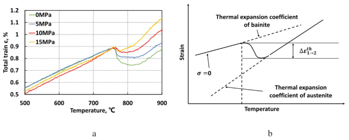
heater and reflecting surface in the electric furnace. The experiment is controlled by a computer program. Fig. 2-3 shows an example of austenite transformation plasticity process (ATP). The specimens are heated to 950℃ at a rate of 5℃/s with different low tensile stresses of 0MPa, 5MPa, 10MPa, 15MPa are started to load just before the austenite transformation initiating temperature and completed after the austenite transformation. The specimens are then slowly cooled to room temperature. It shows an example of cooling process (MTP & BTP). The specimens are heated to 950℃ at a rate of 5℃/s. During cooling the different low tensile stresses of 0MPa, 10MPa, 20MPa, 30MPa are started to load just before the transformation initiating temperature. The tensile loading is followed by Table 2-1. Displacement and strain of the specimens are measured by the installed two quartz glass rod between the target points of 6mm at the specimen center. The relative distance of the quartz glass rod is measured by a displacement measuring device, a GaN green LED light which is made by the Keyence Corporation.
Fig. 2-2 Schematic of tensile test system
Fig. 2-3 Examples of heat treatment process
Table 2-1 Applied load of each stress equivalent
Stress (MPa) Tensile load (N)
5 62.8 10 125.6 15 188.4 20 251.2 30 376.8
2.4 Results
2.4.1 Transformation plasticity during cooling
The specimens were heated to the austenite transformation temperature and stresses
950℃ 5℃/s Time Austenite transformation plasticity process Tem per atur e Bainite transformation plasticity process Martensite transformation plasticity process
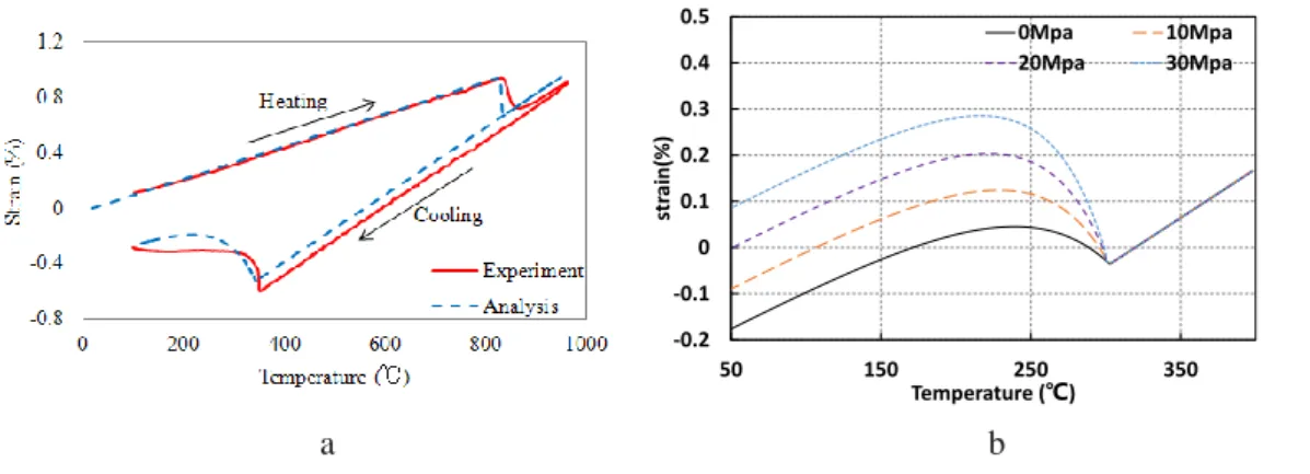
were loaded respectively before bainite transformation and martensitic transformation. The temperature-strain diagrams are obtained by enlarging transformation as shown in Fig. 2-4. Bainite transformation occurs at around 500℃ and martensitic transformation occurs at around 350℃ during cooling. As the simple phase transformation occurs respectively, transformation plasticity behavior can be measureable. Compared to the stress-free, it is seen to have different significantly as the load stress increases. There are only transformation strain and thermal strain in the case of stress-free, while there is also transformation plasticity strain in the case of loading stress. Therefore, subtracting the stress-free strain from loaded stress strain is transformation plasticity strain. In this case, because load stress is under the yield stress point, normal plasticity strain does not occur.
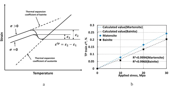
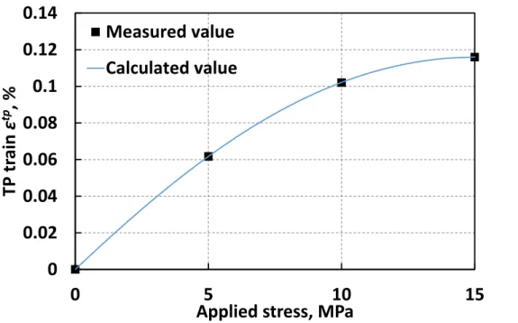
The relationship of stress and transformation plasticity strain obtained from the experimental value is shown in Fig. 2-5. According to the Eq. 46, transformation plasticity coefficient in the martensitic transformation and bainite transformation are constant value in proportion to the stress and transformation plasticity strain. The transformation plasticity coefficients are shown in Table 2-1.
a b
a b
Fig. 2-5 Relation between applied stress and transformation plastic strain for materials examined
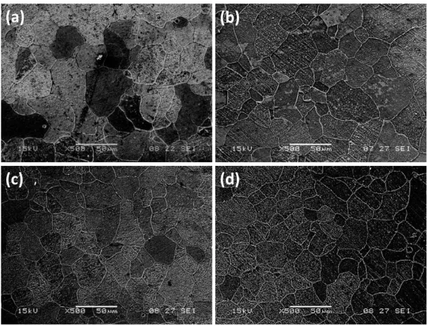
In the experiment, specimens loaded with each stress were processed, and the microstructures were observed using SEM. Using a fine cutter for cutting the specimens, the center of the specimens were machined into a half column shape as shown in Fig. 2-6 and Fig. 2-7. Because the processed specimens were very small and difficult to polish, make a pedestal with copper and polish each foundation.
The cross section of the specimens are first grounded and polished and then the surfaces of the microstructure observation points are eroded with a solution of 4% HNO3 + 96% C2H5OH, the microstructures at different depth from the surface are
finally observed by OM.
a b
Fig. 2-6 (a) Cutting vertically (b) Cutting horizontally
Str ain Temperature 0 0 Thermal expansion coefficient of austenite Thermal expansion coefficient of bainite 0 0.05 0.1 0.15 0.2 0.25 0.3 0 10 20 30 TP tr ain ε tp, %
Applied stress, Mpa