フ ェ ラ イ ト コ ア Fe rr ite C or e
E0
4
フ ェ ラ イ ト コ ア Fe rrit e C oreE0
4
E04
フェライトコア
Ferrite Core
フィルター
UL
RoHS
適合品E04
フェライトコア
Ferrite Core
概要と特長
Product Outline and Features
▶
▶
▶低周波から高周波帯域までのフルラインナップ。
リングタイプ、分割タイプ、フラットタイプなど、お客様のニーズに合わせて
様々なタイプをご用意いたします。
▶低周波分割タイプは、リングタイプと同等
の性能を実現いたします。
•
The full lineup of high-frequency band from
low-frequency band.
To suit your needs, we offer various types, such as
ring-type, split type, flat type etc.
Low-frequency splitting type is equivalent to the
characteristics of ring type.
仕様
Specifications
形状
Dimensions
分割フェライトコア SR・SS・SRMタイプ
Split Cores SR and SS and SRM Types
形番 Part No. 周波数帯域Frequency band 外形寸法(mm) Dimensions 適用ケーブル[最大](mm) Max. Applicable Cable Size A B C D E E04SR311835F 高周波 35.0 ─ 17.5 30.8 12.2 17.5×2.6 E04SR150718 22.0 18.0 ▶ 7.0 15.0 ─ ∅7.0 E04SR200917 21.0 17.0 ▶ 9.0 20.0 ─ ∅9.0 E04SR200932 36.0 32.0 ▶ 9.0 19.5 ─ ∅9.0 E04SR211132 36.0 32.0 11.0 20.5 ─ ∅11.0 E04SR301334 39.0 34.0 13.0 30.0 ─ ∅13.0 E04SR401938 61.0 38.0 19.0 40.0 ─ ∅19.0 E04SR130525A 25.0 20.0 ▶ 5.0 12.8 11.2 ∅3.0~5.0 E04SR130525AB 25.0 20.0 ▶ 5.0 12.8 11.2 ∅3.0~5.0 E04SR170730A 30.0 23.0 ▶ 7.0 16.5 15.0 ∅4.0~7.0 E04SR170730AB 30.0 23.0 ▶ 7.0 16.5 15.0 ∅4.0~7.0 E04SR200935A 35.0 28.0 ▶ 9.0 19.5 17.4 ∅6.0~9.0 E04SR200935AB 35.0 28.0 ▶ 9.0 19.5 17.4 ∅6.0~9.0 E04SR241336A 36.0 29.0 13.0 23.5 22.0 ∅10.0~13.0 E04SR241336AB 36.0 29.0 13.0 23.5 22.0 ∅10.0~13.0 E04SS160816 21.0 ─ ▶ 7.0 22.0 20.0 ∅7.0 E04SS201010 14.0 ─ ▶ 9.0 26.0 24.0 ∅9.0 E04SS231114 18.0 ─ 10.0 29.0 27.0 ∅10.0 E04SS251512 15.0 ─ 14.0 31.0 29.0 ∅14.0 E04SRM281312 低周波 16.0 ─ 12.0 35.0 33.0 ∅12.0 E04SRM381913 17.0 ─ 18.0 45.0 43.0 ∅18.0 E04SRM472715 20.0 ─ 27.0 54.0 52.0 ∅26.0 E04SRM563218 23.0 ─ 32.0 65.0 62.0 ∅31.0 SR▶タイプ:取付方法は結束バンド固定タイプで結束 バンドが1本添付されています。 SR-A、SR-Fタイプ:取付方法はケーブル固定タイプ です。 SR-AB▶タイプ:樹脂ケースは黒色です。 E04SRB:筐体固定タイプ取付孔∅4.8~∅4.9、板厚 0.5~2.0mm▶(E04SR200917用) E04SRMB:筐体固定タイプ取付孔φ4.8~φ4.9 (E04SRMシリーズ用) SR type: Intended to be fastened with a supplied binding band. SR-A,SR-F type : Intended to be fixed to a cable. SR-AB type : The plastic resin case is black. E04SRB : Intended to be fixed to an enclosure. Mounting hole diameter range 4.8-4.9 mm, Thickness range 0.5-2.0mm (for E04SR200917) E04SRB: Intended to be fixed to an enclosure. Mounting hole diameter range 4.8-4.9 SR type SR-F type SR-Fタイプ SR-Aタイプ SSタイプ E04SR401938 SRタイプ
SR-A type E04SRB E04SRMB
SR-AB type SS type E04SR401938 E04SR311835F E C C C C C D E E D D D D A A A A A B B M4用 M4用 B 50.0 30.0 SR-ABタイプ SRMタイプ SRM type A C D E (20.0) (6.0) 19.0 13.0 勘合後の状態図(参考) 50.0 7.0 36.0 40.0 30.05.0 1.5 2-∅4.6 単位:mm in mm NEW▶E04SRMシリーズ
フ ェ ラ イ ト コ ア Fe rr ite C or e
E0
4
フ ェ ラ イ ト コ ア Fe rrit e C oreE0
4
E04
フェライトコア
Ferrite Core
フィルター
UL
RoHS
適合品分割フェライトコア SR・SS・SRMタイプ
Split Cores SR and SS and SRM Types
高周波
低周波
10000 1000 100 10 1E04SR150718
1 10 100 1000 Impedance イ ン ピ ーダ ン ス︵ Ω ︶ Frequency 周波数(MHz) 10000 1000 100 10 1E04SR211132
1 10 100 1000 Impedance イ ン ピ ーダ ン ス︵ Ω ︶ Frequency 周波数(MHz) 10000 1000 100 10 1E04SR301334
1 10 100 1000 Impedance イ ン ピ ーダ ン ス︵ Ω ︶ Frequency 周波数(MHz) 10000 1000 100 10 1E04SR130525A E04SR130525AB
1 10 100 1000 Impedance イ ン ピ ーダ ン ス︵ Ω ︶ Frequency 周波数(MHz) 10000 1000 100 10 1E04SS160816
1 10 100 1000 Impedance イ ン ピ ーダ ン ス︵ Ω ︶ Frequency 周波数(MHz) 10000 1000 100 10 1E04SS231114
1 10 100 1000 Impedance イ ン ピ ーダ ン ス︵ Ω ︶ Frequency 周波数(MHz) 10000 1000 100 10 1E04SS251512
1 10 100 1000 Impedance イ ン ピ ーダ ン ス︵ Ω ︶ Frequency 周波数(MHz)E04SRM381913
Impedance イ ン ピ ーダ ン ス︵ Ω ︶ Frequency 周波数(MHz)E04SRM472715
Impedance イ ン ピ ーダ ン ス︵ Ω ︶ Frequency 周波数(MHz) 10000 1000 100 10 1E04SR200932
1 10 100 1000 Impedance イ ン ピ ーダ ン ス︵ Ω ︶ Frequency 周波数(MHz) 10000 1000 100 10 1E04SR401938
1 10 100 1000 Impedance イ ン ピ ーダ ン ス︵ Ω ︶ Frequency 周波数(MHz) 10000 1000 100 10 1E04SR200935A E04SR200935AB
1 10 100 1000 Impedance イ ン ピ ーダ ン ス︵ Ω ︶ Frequency 周波数(MHz) 10000 1000 100 10 1E04SS201010
1 10 100 1000 Impedance イ ン ピ ーダ ン ス︵ Ω ︶ Frequency 周波数(MHz) 1000 1 100 10E04SRM281312
0.1 1 10 1000 1 100 10 0.1 1 10 1000 1 100 10 0.1 1 10 1000 1 100 10 0.1 1 10 Impedance イ ン ピ ーダ ン ス︵ Ω ︶ Frequency 周波数(MHz)E04SRM563218
Impedance イ ン ピ ーダ ン ス︵ Ω ︶ Frequency 周波数(MHz) 1Turn 2Turns 3Turns 1Turn 2Turns 3Turns 1Turn 2Turns 3Turns 1Turn 2Turns 3Turns 1Turn 2Turns 3Turns 1Turn 2Turns 3Turns 1Turn 2Turns 3Turns 1Turn 2Turns 3Turns 1Turn 2Turns 3Turns 1Turn 2Turns 3Turns 1Turn 2Turns 3Turns 1Turn 2Turns 3Turns 1Turn 2Turns 3Turns 1Turn 2Turns 3Turns 1Turn 2Turns 3Turns 10000 1000 100 10 1E04SR311835F
1 10 100 1000 Impedance イ ン ピ ーダ ン ス︵ Ω ︶ Frequency 周波数(MHz) 10000 1000 100 10 1E04SR200917
1 10 100 1000 Impedance イ ン ピ ーダ ン ス︵ Ω ︶ Frequency 周波数(MHz) 1Turn 2Turns 3Turns 10000 1000 100 10 1E04SR170730A E04SR170730AB
1 10 100 1000 Impedance イ ン ピ ーダ ン ス︵ Ω ︶ Frequency 周波数(MHz) 1Turn 2Turns 3Turns 10000 1000 100 10 1E04SR241336A E04SR241336AB
1 10 100 1000 Impedance イ ン ピ ーダ ン ス︵ Ω ︶ Frequency 周波数(MHz) 1Turn 2Turns 3Turnsインピーダンス特性
Impedance-frequency Curve
フ ェ ラ イ ト コ ア Fe rr ite C or e
E0
4
フ ェ ラ イ ト コ ア Fe rrit e C oreE0
4
E04
フェライトコア
Ferrite Core
E04
フェライトコア
Ferrite Core
▶
▶
低周波から高周波帯域までのフルラインナップ。
▶
▶
外径∅8.0~∅61.0まで取り揃えています。
▶
▶
E04RMの表面には、絶縁性の高い塗装を施しています。
•
The full lineup of high-frequency band from low-frequency band.
•
Non-split ring cores are available in a wide diameter range from 8.0 to 61.0.
•
The surface is coated with insulating paint. (E04RM type)
形番 Part No. 周波数帯域Frequency band 外形寸法(mm) Dimensions A B C E04RA080040030 高周波 ▶ 8.0▶ ▶ 4.0▶ ▶ 3.0▶ E04RA100060100 10.0▶ ▶ 6.0▶ 10.0▶ E04RA100060140 10.0▶ ▶ 6.0▶ 14.0▶ E04RA120070060 12.0▶ ▶ 7.0▶ ▶ 6.0▶ E04RA120080130 12.0▶ ▶ 8.0▶ 13.0▶ E04RA140035280 14.0▶ ▶ 3.5▶ 28.0▶ E04RA140064280 14.0▶ ▶ 6.3▶ 28.0▶ E04RA140070100 14.0▶ ▶ 7.0▶ 10.0▶ E04RA160070200 16.0▶ ▶ 7.0▶ 20.0▶ E04RA160100140 16.0▶ 10.0▶ 14.0▶ E04RA190120080 19.0▶ 12.0▶ ▶ 8.0▶ E04RA260130280 26.0▶ 13.0▶ 28.0▶ E04RA310190100 31.0▶ 19.0▶ 10.0▶ E04RA400270150 40.0▶ 27.0▶ 15.0▶ E04RM201010 低周波 20.0▶ 10.0 10.0▶ E04RM251512 25.0▶ 15.0▶ 12.0▶ E04RM381913 38.0▶ 19.0▶ 12.7 E04RM472715 47.0▶ 27.0▶ 15.0▶ 形番 Part No. 周波数帯域Frequency band 外形寸法(mm) Dimensions A B C E04RC100505 高周波 10.0▶ ▶ 5.0 ▶ 5.0 E04RC110519 11.0▶ ▶ 5.0 18.5 E04RC120715 11.8▶ ▶ 7.3 15.0 E04RC120916 12.0▶ ▶ 8.5 16.0 E04RC151008 14.5▶ 10.2 ▶ 8.0 E04RC150719 15.0▶ ▶ 7.0 19.0 E04RC160928 16.0▶ ▶ 9.0 28.0 E04RC161010 16.0▶ 10.0 10.0 E04RC170813 16.5▶ ▶ 8.2 13.0 E04RC170816 16.5▶ ▶ 8.2 16.0 E04RC181006 17.5▶ ▶ 9.5 ▶ 6.4 E04RC181029 17.5▶ ▶ 9.5 28.5 E04RC211010 20.5▶ 10.2 10.0 E04RC241114 23.6▶ 11.4 14.0 E04RC251512 25.0▶ 15.0 12.0 E04RC281613 28.0▶ 16.0 13.0 E04RC281620 28.0▶ 16.0 20.0 E04RC311908 31.0▶ 19.0 ▶ 8.0 E04RC613620 61.0▶ 35.5 20.0RoHS
適合品フィルター
インピーダンス特性
Impedance-frequency Curve
概要と特長
Product Outline and Features
形状
Dimensions
非分割フェライトコア RA・RC・RMタイプ
Non-split Ring Cores RA and RC and RM Types
RA and RC types
RA・RCタイプ
A C B 10000 1000 100 10 1E04RC120916
1 10 100 1000 Impedance イ ン ピ ーダ ン ス︵ Ω ︶ Frequency 周波数(MHz) 10000 1000 100 10 1E04RC161010
1 10 100 1000 Impedance イ ン ピ ーダ ン ス︵ Ω ︶ Frequency 周波数(MHz) 10000 1000 100 10 1E04RC251512
1 10 100 1000 Impedance イ ン ピ ーダ ン ス︵ Ω ︶ Frequency 周波数(MHz) 1000 100 10 1 0.1E04RM201010
0.01 0.1 1 10 Impedance イ ン ピ ーダ ン ス︵ Ω ︶ Frequency 周波数(MHz) 1000 100 10 1 0.1E04RM251512
0.01 0.1 1 10 Impedance イ ン ピ ーダ ン ス︵ Ω ︶ Frequency 周波数(MHz) 1000 100 10 1 0.1E04RM381913
0.01 0.1 1 10 Impedance イ ン ピ ーダ ン ス︵ Ω ︶ Frequency 周波数(MHz) 1000 100 10 1 0.1E04RM472715
0.01 0.1 1 10 Impedance イ ン ピ ーダ ン ス︵ Ω ︶ Frequency 周波数(MHz) 1Turn 2Turns 3Turns 1Turn 2Turns 3Turns 1Turn 2Turns 3Turns 1Turn 2Turns 3Turns 1Turn 2Turns 3Turns 1Turn 2Turns 3Turns 1Turn 2Turns 3Turns ※記載の特性データは実測値であり保証値ではありません。 ※▶特性図(インピーダンス特性)はWebで公開しています。(http:▶//www.seiwa.co.jp/emc/)▶ *The above characteristic data are not guaranteed data but actual measurements. *▶You can see characteristic graphs (Z-f curve) for EMC products at our website. (http: //www.seiwa.co.jp/emc/)フ ェ ラ イ ト コ ア Fe rr ite C or e
E0
4
フ ェ ラ イ ト コ ア Fe rrit e C oreE0
4
E04
フェライトコア
Ferrite Core
▶
▶
▶配線済ケーブルに容易に装着可能です。
•
Countermeasures against unwanted radiation or noise
terminal voltage caused by interface cables for various
digital devices or immunity enhancement measures.
形番 Part No. 外形寸法(mm) Dimensions A B C D E F E04ST161014D 18.0 30.0 9.5 4.3 10.0 14.0 E04ST201010D 23.0 36.0 12.7 5.0 10.0 10.0 E04ST251512D 28.0 41.0 12.7 5.0 15.0 12.0 E04ST281613D 31.0 43.0 12.7 5.0 16.0 13.0 E04ST402715D 42.0 55.0 12.7 5.0 27.0 15.0インピーダンス特性
Impedance-frequency Curve
概要と特長
Product Outline and Features
形状
Dimensions
分割フェライトコア ナイロンクランプ STタイプ
Split Ring Cores with Clamps(nylon) ST Type
RoHS
適合品フィルター
φD A B F C E Ferrite core フェライトコア Nylon clamp ナイロンクランプ Nylon 66 (UL94 V-2) 材質:ナイロン66(UL94 V-2)▶
▶
▶2分割型のため、配線ケーブルへの装着が容易。
•
A split ferrite core can be easily fitted to a cable fixed in place.
形番 Part No. 外形寸法(mm) Dimensions 適応フラット ケーブル芯数 No. of Wires per Flat Cable A B C D E F ReferenceF参考 G ReferenceG参考 E04SF360270127 10.0 36.0 12.7 2.0 27.0 12.0 38.0 20 E04SF440350127 10.0 44.0 12.7 2.0 35.0 12.0 46.0 26 E04SF800686127 10.0 80.0 12.7 2.6 68.6 12.0 82.0 50インピーダンス特性
Impedance-frequency Curve
概要と特長
Product Outline and Features
形状
Dimensions
分割フェライトコア FFC用フェライトコア SFタイプ
Ferrite Cores for FFC SF Type
Retainer F B E D A C G 保持具 10000 1000 100 10 1
E04ST161014D
1 10 100 1000 Impedance イ ン ピ ーダ ン ス︵ Ω ︶ Frequency 周波数(MHz)E04ST201010D
E04ST251512D
E04ST281613D
10000 1000 100 10 11 10 100 1000 Impedance イ ン ピ ーダ ン ス︵ Ω ︶ Frequency 周波数(MHz) 10000 1000 100 10 11 10 100 1000 Impedance イ ン ピ ーダ ン ス︵ Ω ︶ Frequency 周波数(MHz) 10000 1000 100 10 11 10 100 1000 Impedance イ ン ピ ーダ ン ス︵ Ω ︶ Frequency 周波数(MHz) 10000 1000 100 10 11 10 100 1000 Impedance イ ン ピ ーダ ン ス︵ Ω ︶ Frequency 周波数(MHz)E04ST402715D
1Turn 2Turns 3Turns 1Turn 2Turns 3Turns 1Turn 2Turns 3Turns 1Turn 2Turns 3Turns 1Turn 2Turns 3Turns ※記載の特性データは実測値であり保証値ではありません。 ※▶特性図(インピーダンス特性)はWebで公開しています。 (http:▶//www.seiwa.co.jp/emc/)▶ *The above characteristic data are not guaranteed data but actual measurements. *▶You can see characteristic graphs (Z-f curve) for EMC products at our website. (http: //www.seiwa.co.jp/emc/)E0SF360270127
1000 100 10 11 10 100 1000 Impedance イ ン ピ ーダ ン ス︵ Ω ︶ Frequency 周波数(MHz) 1000 100 10 11 10 100 1000 Impedance イ ン ピ ーダ ン ス︵ Ω ︶ Frequency 周波数(MHz)E04SF440350127
1000 100 10 11 10 100 1000 Impedance イ ン ピ ーダ ン ス︵ Ω ︶ Frequency 周波数(MHz)E04SF800686127
※記載の特性データは実測値であり保証値ではありません。 ※▶特性図(インピーダンス特性)はWebで公開しています。(http:▶//www.seiwa.co.jp/emc/)▶ *The above characteristic data are not guaranteed data but actual measurements. *▶You can see characteristic graphs (Z-f curve) for EMC products at our website. (http: //www.seiwa.co.jp/emc/)フ ェ ラ イ ト コ ア Fe rr ite C or e
E0
4
フ ェ ラ イ ト コ ア Fe rrit e C oreE0
4
E04
フェライトコア
Ferrite Core
E04
フェライトコア
Ferrite Core
形番 Part No. 外形寸法(mm) Dimensions 適用ケーブル Applicable Cable A B C D E E04FG170808 ▶ 5.0 21.0 ▶ 8.0 0.8 17.0 FPC用 for FPC E04FG200712 ▶ 3.0 23.0 12.0 0.7 20.0 E04FG210810 ▶ 3.0 25.0 10.0 0.8 21.0 E04FG270712 ▶ 3.0 31.0 12.0 0.7 27.0 E04FG280808 ▶ 5.0 32.0 ▶ 8.0 0.8 28.0 E04FG280812 ▶ 5.0 32.0 12.0 0.8 28.0 E04FG280820 ▶ 5.0 32.0 20.0 0.8 28.0 E04FG340812 ▶ 5.0 38.0 12.0 0.8 34.0 E04FG460808 ▶ 5.0 50.0 ▶ 8.0 0.8 46.0 E04FG460812 ▶ 5.0 50.0 12.0 0.8 46.0 E04FG530812 ▶ 5.0 57.0 12.0 0.8 53.0 E04FG171308 ▶ 6.5 21.5 ▶ 8.0 1.3 16.5 FFC用 for FFC E04FG191308 ▶ 6.5 24.0 ▶ 8.0 1.3 19.0 E04FG221308 ▶ 6.5 27.0 ▶ 8.0 1.3 22.0 E04FG221312 ▶ 6.5 27.0 12.0 1.3 22.0 E04FG281308 ▶ 6.5 33.5 ▶ 8.0 1.3 28.0 E04FG281310 ▶ 6.5 33.5 10.0 1.3 28.0 E04FG281312 ▶ 6.5 33.5 12.0 1.3 28.0 E04FG351312 ▶ 6.5 40.0 12.0 1.3 34.8 E04FG401308 ▶ 6.5 45.2 ▶ 8.0 1.3 40.0 E04FG401312 ▶ 6.5 45.2 12.0 1.3 40.0 E04FG441308 ▶ 6.5 49.8 ▶ 8.0 1.3 44.0 E04FG441312 ▶ 6.5 49.6 12.0 1.3 44.0 E04FG521312 ▶ 7.0 57.9 12.0 1.3 52.0 E04FA310280120 ▶ 3.0 31.0 12.0 0.8 28.0 FPC用 for FPC E04FA380340120 ▶ 5.0 38.0 12.0 0.8 34.0 E04FA460420120 ▶ 5.0 46.0 12.0 0.8 42.0 E04FA570530120 ▶ 5.0 57.0 12.0 0.8 53.0 E04FA217165080 ▶ 6.5 21.7 ▶ 8.0 1.3 16.5 12 E04FA270218080 ▶ 6.5 27.0 ▶ 8.0 1.3 21.8 16 E04FA330278080 ▶ 6.5 33.0 ▶ 8.0 1.3 27.8 20 E04FA330278120 ▶ 6.5 33.0 12.0 1.3 27.8 20 E04FA400348120 ▶ 6.5 40.0 12.0 1.3 34.8 26 E04FA480420080 ▶ 8.0 48.0 ▶ 8.0 2.0 42.0 32 E04FA507447120 ▶ 8.0 50.7 12.0 2.0 44.7 32 E04FA600520120 10.0 60.0 12.0 2.0 52.0 40
RoHS
適合品フィルター
FPC、FFC用フェライトコア FG・FAタイプ
Ferrite Cores for FPC and FFC FG and FA Types
形番 Part No. 外形寸法(mm) Dimensions A B C D E E04FD070503 2.0 ▶ 9.5 ▶ 3.0 0.5 ▶ 7.0 E04FD070504 2.0 ▶ 9.5 ▶ 4.0 0.5 ▶ 7.0 E04FD070505 2.0 ▶ 9.5 ▶ 5.0 0.5 ▶ 7.0 E04FD110503 2.0 13.5 ▶ 3.0 0.5 11.0 E04FD110504 2.0 13.5 ▶ 4.0 0.5 11.0 E04FD110505 2.0 13.5 ▶ 5.0 0.5 11.0 E04FD110506 2.0 13.5 ▶ 6.0 0.5 11.0 E04FD110508 2.0 13.5 ▶ 8.0 0.5 11.0 E04FD110510 2.0 13.5 10.0 0.5 11.0 E04FD130503 2.0 15.5 ▶ 3.0 0.5 13.0 E04FD130504 2.0 15.5 ▶ 4.0 0.5 13.0 E04FD130505 2.0 15.5 ▶ 5.0 0.5 13.0 E04FD130506 2.0 15.5 ▶ 6.0 0.5 13.0 E04FD130508 2.0 15.5 ▶ 8.0 0.5 13.0 E04FD130510 2.0 15.5 10.0 0.5 13.0
形状
Dimensions
FPC用フェライトコア FDタイプ
Ferrite Cores for FPC FD Type
B E D A C
▶
▶
豊富なサイズバリエーションによりお望みのサイズが選べます。
•
You can choose the size of the wide variations depending on the size you wish.
フ ェ ラ イ ト コ ア Fe rr ite C or e
E0
4
フ ェ ラ イ ト コ ア Fe rrit e C oreE0
4
1 10 100 1000 1 10 100 1000E04FG200712
Frequency 周波数(MHz) Impedance イ ン ピ ーダ ン ス︵ Ω ︶E04FG280808
E04FG460808
E04FG171308
E04FG281312
E04FG441312
E04FA380340120
E04FA270218080
E04FA480420080
E04FD070505
E04FD130503
E04FD130510
1 10 100 1000 1 10 100 1000 Frequency 周波数(MHz) Impedance イ ン ピ ーダ ン ス︵ Ω ︶ 1 10 100 1000 1 10 100 1000 Frequency 周波数(MHz) Impedance イ ン ピ ーダ ン ス︵ Ω ︶ 1 10 100 1000 1 10 100 1000 Frequency 周波数(MHz) Impedance イ ン ピ ーダ ン ス︵ Ω ︶ 1 10 100 1000 1 10 100 1000 Frequency 周波数(MHz) Impedance イ ン ピ ーダ ン ス︵ Ω ︶ 1 10 100 1000 1 10 100 1000 Frequency 周波数(MHz) Impedance イ ン ピ ーダ ン ス︵ Ω ︶ 1 10 100 1000 1 10 100 1000 Frequency 周波数(MHz) Impedance イ ン ピ ーダ ン ス︵ Ω ︶ 1 10 100 1000 1 10 100 1000 Frequency 周波数(MHz) Impedance イ ン ピ ーダ ン ス︵ Ω ︶ 1 10 100 1000 1 10 100 1000 Frequency 周波数(MHz) Impedance イ ン ピ ーダ ン ス︵ Ω ︶ 1 10 100 1000 1 10 100 1000 Frequency 周波数(MHz) Impedance イ ン ピ ーダ ン ス︵ Ω ︶ 1 10 100 1000 Frequency 周波数(MHz) Impedance イ ン ピ ーダ ン ス︵ Ω ︶ 1 10 100 1000 Frequency 周波数(MHz) Impedance イ ン ピ ーダ ン ス︵ Ω ︶ 1000 100 10 1 0.1 1000 100 10 1 0.1
E04FG270712
1 10 100 1000 1 10 100 1000 Frequency 周波数(MHz) Impedance イ ン ピ ーダ ン ス︵ Ω ︶E04FG340812
1 10 100 1000 1 10 100 1000 Frequency 周波数(MHz) Impedance イ ン ピ ーダ ン ス︵ Ω ︶E04FG401312
1 10 100 1000 1 10 100 1000 Frequency 周波数(MHz) Impedance イ ン ピ ーダ ン ス︵ Ω ︶E04
フェライトコア
Ferrite Core
インピーダンス特性
Impedance-frequency Curve
RoHS
適合品フィルター
※記載の特性データは実測値であり保証値ではありません。 ※特性図(インピーダンス特性)はWebで公開しています。(http:▶//www.seiwa.co.jp/emc/)▶ *The above characteristic data are not guaranteed data but actual measurements. *You can see characteristic graphs (Z-f curve) for EMC products at our website. (http: //www.seiwa.co.jp/emc/)フ ェ ラ イ ト コ ア Fe rr ite C or e
E0
4
フ ェ ラ イ ト コ ア Fe rrit e C oreE0
4
E04
フェライトコア
Ferrite Core
フィルター
UL
RoHS
適合品E04
フェライトコア
Ferrite Core
取り付け方法
Method of mounting
E04SR-A/E04SR-AB タイプ
樹脂ケースの爪で簡単に固定が可能です。
It can be fixed easily with the nail of a resin case.E04SRM シリーズ
オプションの台座(E04SRMB)で固定可能です。
It is fixable by the pedestal (E04SRMB) of an option.E04SR200917
オプションの台座(E04SRB)で固定可能です。
It is fixable by the pedestal (E04SRB) of an option.E04SR401938
M4サイズのビスで固定可能です。
It can be fixed with M4 size screws.E04SR タイプ
結束バンドで固定可能です。
It can be fixed with binding band.フ ェ ラ イ ト コ ア Fe rr ite C or e
E0
4
フ ェ ラ イ ト コ ア Fe rrit e C oreE0
4
E04
フェライトコア
Ferrite Core
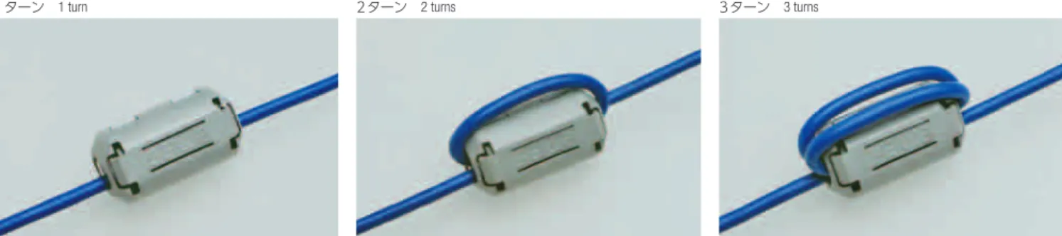
1ターンでインピーダンスが足りない場合、2ターン、3ターンと巻数
を増やすことでインピーダンスを大きくすることが出来ます。インピー
ダンスはターン数の2乗倍で大きくなります。ただし、図3に示す通り高
周波では線間容量の影響である周波数を越えるとインピーダンスが減
少するため、適応周波数を考慮する必要があります。
フェライトコアの使用数を増やすと図4に示す通り、使用数に比例して
インピーダンスは増加します。
フェライトコアを後付けする場合、分割型を使用すれば簡単に取り付
ける事が出来ます。分割型の切断面はギャップが生じない様に加工
されているため、図5の分割型と非分割型を比較しても特性は殆ど
変わりません。但し、塵などが切断面に入りギャップが生じると図5の
ギャップに示す通り低い周波数でインピーダンスが大幅に低下しま
すので、切断面に塵などが入りギャップが生じない様に取り付けて下
さい。
A split ferrite core is easily fitted to a cable fixed in place. The split core is designed
to eliminate the joint gap. As shown in Fig. 5, the characteristics of the split ferrite
core are almost the same as those of the non-split (standard) ferrite core. However,
if dust or foreign matter should get into the joint and produce a gap, the imped-
ance would considerably decline at low frequencies as indicated by the curve rep-resenting the gapped ferrite core. Therefore, when fitting the split core, care should
be taken not to allow dust to get into the joint.
If impedance is insufficient as a result of the cable passing through the ferrite core
once (1 turn), impedance can be increased by passing the cable through it twice or
three times. Impedance increases with the square of the number of turns. However,
as shown in Fig. 3, because of line capacity, impedance begins to go down when the
frequency exceeds a certain level, so the frequency employed should be determined
carefully.
When the number of cores in use is increased, impedance goes up in proportion to
the number of cores, as shown in Fig. 4.
技術資料
Technical Information
RoHS
適合品UL
フィルター
1ターン 1 turn 2ターン 2 turns 3ターン 3 turns
10000 1000 100 10 1 1 10 100 1000 Impedance イ ン ピ ーダ ン ス︵ Ω ︶ Frequency 周波数(MHz) 1Turn 2Turns 3Turns ① ② ③ 10000 1000 100 10 1 1 10 100 1000 Impedance イ ン ピ ーダ ン ス︵ Ω ︶ Frequency 周波数(MHz) 1 Core 2 Cores 3 Cores 1個 2個 3個 ① ② ③ 10000 1000 100 10 1 1 10 100 1000 Impedance イ ン ピ ーダ ン ス︵ Ω ︶ Frequency 周波数(MHz) Non-split Split Gapped 非分割型 分割型 ギャップ 図3 インピーダンスと巻数の関係 Fig. 3 Relation between Impedance and No. of Turns 図4 インピーダンスとフェライトコア数の関係Fig. 4 Relation between Impedance and No. of Cores 図5 インピーダンスとギャップの関係 Fig. 5 Relation between Impedance and Gaps