宇宙航空研究開発機構研究開発資料
JAXA Research and Development Memorandum
2017年3月
宇宙航空研究開発機構
Japan Aerospace Exploration AgencyJAXA-RM-16-007
クローズドサイクル希釈冷凍機の圧縮機開発および
希釈冷凍機システム評価試験
満田 和久*2
、中川 貴雄*2
Keisuke Shinozaki∗1,
Kenichiro Sawada∗1,
Yohichi Satoh∗1,
Kohsuke Tanaka∗1, Hiroyuki Sugita∗1
, Kazuhisa Mistuda∗2
and Takao Nakagawa∗2
Abstract
宇宙を観測する宇宙科学ミッションなどで使われる高感度観測装置は、微弱な電磁波を高精 度に捉えられるよう、検出信号の雑音(特に熱雑音) を低減させる必要がある。そのため、検 出器を絶対零度(約-273 ℃) 近くまで冷却して動作させる。宇宙用希釈冷凍機は、このよう な高感度観測装置に求められる100 mK という極低温を、宇宙空間において無磁場かつ高い冷 凍能力(オープンサイクル式の100 mKでの冷凍能力0.1 μWに対して、50 mKにて10倍の 1 μW)を獲得し、同時に軽量化(オープンサイクル式用冷媒タンクが不要) と大幅な長寿命化 (1.5→ 5年) を可能とする。
本研究は、クローズドサイクル希釈冷凍機(CCDR : Closed-Cycle Dilution Refigerator) の実 現に必須となる、冷媒であるヘリウム3を低圧で循環するための圧縮機システムの開発と、フ ランスと共同で構築したクローズドサイクル希釈冷凍機システムのシステム評価試験を2つの 柱としている。特に後者は、100 mK 以下において高い冷凍能力を長寿命に作り出す次世代の 宇宙用冷凍機として、フランスの研究機関と協力しながら進めた世界初の技術実証となった。 2015 年5月にフランスにて行われた地上技術実証では、本実験設計上の最低到達温度である
70 mKを達成し、冷凍能力などの冷却特性評価試験も追加で行うことができた。また、測定結
果に基づいた解析により、50 mKでの冷凍能力1 μWを実現するための設計解を得ることがで き、当初の目標を達成することができた。
本稿では、2011年度より宇宙航空研究開発機構研究開発部門第二研究ユニット(旧研究開発 本部熱グループ) が中心に進めた、ヘリウム3循環圧縮機システムの研究開発、およびクロー ズドサイクル希釈冷凍機システムのシステム評価試験についてまとめる。第1章では研究開発 の背景となる、宇宙用機械式冷凍機の研究開発の意義や、クローズドサイクル希釈冷凍機の研 究開発の意義について述べる。第2章では、希釈冷凍機の基本原理や求められる冷凍能力、そ れより求められるヘリウム3循環圧縮機システムの目標性能についてまとめる。第3章および 第4章では、試作された圧縮機システムの設計製作や単体性能評価試験結果について述べる。 最後に、第5章ではフランス担当の低温部と組み合わせたシステム評価試験結果についてまと めている。
*
平成28年12月15日受付 (Received 15, December, 2016)
*1
研究開発部門第二研究ユニット (Research Unit Ⅱ, Research and Development Directorate)
*2 宇宙科学研究所 宇宙物理学研究系
Contents
0.1 Abbreviations and acronyms ··· 5
1 研究開発の背景および目的 6
1.1 宇宙用機械式冷凍機の研究開発 ··· 6
1.2 断熱消磁冷凍機と希釈冷凍機 ··· 6
1.3 宇宙用クローズドサイクル希釈冷凍機の研究開発 ··· 9
2 クローズドサイクル希釈冷凍機システムの構成と目標性能 11
2.1 希釈冷凍機の冷却原理 ··· 11
2.2 クローズドサイクル希釈冷凍機に求められる冷凍能力 ··· 12
2.3 ヘリウム 3 循環圧縮機システムに求められる性能 2.3.1 初期の冷却試験(F.Martin et al. Cryogenics 2010)[1] ··· 12
2.3.2 2011 年のフランス側冷却試験結果 ··· 14
2.3.3 2012 年のフランス側冷却試験結果 ··· 14
2.3.4 要求吸込圧 ··· 14
2.3.5 要求作動ガス流量 ···15
2.4 ヘリウム3 循環圧縮機システムの目標性能のまとめ ···15
2.5 想定される冷凍機システム ··· 16
3 ヘリウム 3 を循環する圧縮機システムの設計製作 17
4 ヘリウム 3 を循環する圧縮機システムの性能評価 20
5 希釈冷凍機システムのシステム評価試験 22
5.1 Test 1 : 100 mKにてHelium-3 循環運転を地上用循環pump から圧縮機へ切り替え ·· 22
5.2 Test 2 : 1 K 以上から冷却 ··· 24
5.3 Test 3 : 15 K 以上から冷却 ··· 24
6 まとめ 27
A システム評価試験ログ 28
B 発表資料 “Development of helium-3 compressors and integration test of closed-cycle dilution refrigerator system”, 30th International Symposium on Space Technology and Science, Kobe, Japan (2015) 29
C 発表資料 “ 宇宙用クローズドサイクル希釈冷凍機の実現に向けたヘリウム3 循環圧縮機の開発結果 ”, 第59 回宇宙科学技術連合講演会3M16 (2015) 43
1K-JT 1K-class Joule Thomson cooler
2ST Double-stage Stirling cooler
4K-JT 4K-class Joule Thomson cooler
ADR Adiabatic Demagnetization Refrigerator
AXAF Advanced X-ray Astrophysics Facility
BBM Bread Board Model
CCDR Closed-Cycle Dilution Refrigerator
CNES Centre national d’etudes spatiales
CNRS Centre national de la recherche scientiique FP Founatain pump
HX Heat Exchanger
宇宙航空研究開発機構研究開発資料 JAXA-RM-16-007
6 凍機の圧縮機開発および希
釈冷凍機システム評価試験
1
研究開発の背景および目的
1.1
宇宙用機械式冷凍機の研究開発
宇宙機において望遠鏡や観測装置を冷却する技術は、より遠くあるいは微弱な観測対象に対し てより詳細な観測を可能とし、宇宙科学衛星の観測技術を決めるキー技術となっている。また、 地球観測衛星や惑星探査機においては、高感度赤外センサの信号の熱雑音を抑えるために必須 の技術である。宇宙開発の黎明期では、宇宙機における冷却といえば液体ヘリウムなどを用い た寒剤冷却で、バス部を上回る大きな寒剤タンクを設計し、打ち上げ直前まで蒸発を抑えよう
とする複雑な運用を強いられながら充填作業を続け、それでも観測寿命は1~2年足らずがほと
んどであった。無寒剤の機械式冷凍機の開発は、ミッション部の軽量化と長寿命化を望めば当 然の流れといえる。
宇宙航空研究開発機構 研究開発部門では、この高感度観測装置の最重要技術の一つである
極低温冷却技術において、世界最高の熱効率(入力電力 / 生成温度における冷凍能力)を誇る
無寒剤の機械式冷凍機 (2段スターリング冷凍機、ジュールトムソン冷凍機)を研究開発してき
た[2, 3, 4]。これらの冷凍機を組み合わせた冷却システムにより、最先端宇宙科学ミッションの
競争力はさらに高まり、また、システムの小型化、低コスト化、長寿命化にも有効なことから、 今後も宇宙科学ミッションへの大きな貢献が期待される。
1.2
断熱消磁冷凍機と希釈冷凍機
100 mK以下を作り出す主要な冷却手段としては、磁気冷凍の一つである断熱消磁冷凍と、ヘ
リウムを用いた希釈冷凍の2つがある。
断熱消磁冷凍機(Adiabatic Demagnetization Refrigerator = ADR)は、極低温における常
磁性体の磁気的な状態変化を利用し、磁場を用いたカルノーサイクルで低温を作り出す冷却手
段である。ADRは主に磁性体カプセル(pill)、磁性体に強磁場をかけるための超伝導マグネッ
ト、熱浴と磁性体との間の熱的On/Offを作り出すヒートスイッチの3要素で構成され、とても
シンプルな構造となる。地上用の冷却手段としては、希釈冷凍機が大きく普及するにつれて、 研究分野として衰退した時期があった。その後、米国のAXAF (Advanced X-ray Astrophysics
Facility)計画において宇宙空間で100 mK以下を作り出す冷凍機の検討が始まり、ADRは原理
的に重力の影響を受けない宇宙用冷却技術として再び注目された[5, 6]。
ADRが初めて宇宙機に搭載されたのは、日本で5番目のX線天文衛星すざく(Astro-EII、
2005年打上げ)である[7, 8]。これは、それまで衛星搭載されていたX線CCDなどの検出器よ
りも10倍以上優れたエネルギー分解能を持つ半導体型X線マイクロカロリメータを極低温で
Figure 1: 断熱消磁冷凍機(単段式)の概念図。
た。また、宇宙用として近年では多段式ADRが主流になりつつある。2016年に打ち上げられ
た日本で6番目のX線天文衛星ひとみには、上記の半導体マイクロカロリメータの冷却のため
に3段式ADRが搭載され、軌道上にて50 mK の生成に成功している[9, 10, 11]。また、多段
式の各段の冷却サイクルを交互に行い、連続的に100 mK以下を作り出す連続型ADRが研究
開発されている[12]。これにより、リサイクル時間というDead time (観測ができない時間) が 消えると同時に、冷凍能力向上ももたらすことができ、地上の冷却手段としても期待がかかる。
希釈冷凍機は、1 K以下の混合室(Mixing chamber)にて、ヘリウム4 (4
He)とその同位体で あるヘリウム3 (3
He) の比率が異なる2相間で3
Heが移動することにより、吸熱反応が起こっ
て冷却が行われる。ADRの冷凍能力の限界を決めている最大の要因は、冷媒が液体あるいは気
体ではなく固体である点である (これは高い温度安定性を作り出すためには利点でもある)。し
たがって、希釈冷凍機は、地上においてはクライオスタット外部に冷媒であるヘリウムの貯蔵
タンクを設け、タンクから低温部へ気体ヘリウムを循環させることで、ADRより高い冷凍能力
を容易に作り出すことができる。
しかし、希釈冷凍サイクルでは、d相 (dilute phase、6.6 %の3
He と93.4 %の4
He)中の3
He
を選択的に抽出し循環させるために、混合室の中で3
Heのみとなるc相 (concentrated phase)
とd相を分離させる必要があり、地上用冷凍機における通常の方法では重力を利用している。
さらに、大きな高圧貯蔵タンクの搭載は、衛星システム設計にとって大きなインパクトである。
宇宙背景放射観測衛星Planckに搭載されたオープンサイクル希釈冷凍機は、「重力利用」と
いう壁を越えて宇宙用希釈冷凍機を実現した最初の衛星である[13, 14, 15, 16]。本冷凍機では
宇宙航空研究開発機構研究開発資料 JAXA-RM-16-007
8 凍機の圧縮機開発および希
釈冷凍機システム評価試験
Figure 2: 宇宙背景放射観測衛星Planckに搭載されたService moduleから検出器ボロメータまでの冷却システム [13]。
Figure 3: クローズドサイクル3 He -4
から検出器ボロメータまでの冷却システムを図 2に示す[13]。冷媒であるヘリウムは、別に用
意されたジュールトムソン冷凍機によって4.5 Kに予冷され、さらに混合室から伸びるReturn
配管中のヘリウムガスを用いたジュールトムソン冷却により、1.6 K未満に予冷される。室温
部には4台の貯蔵タンク(1台あたりの体積51ℓ)が設けられ、冷媒であるヘリウムは1タンク
あたり約10,590ℓ搭載される。これにより、100 mKにて0.1 µWの冷凍能力を得るための流量
(4
He 22.5 µmol/sec、3
He 7.5 µmol/sec) を実現する。
Planckに搭載されたオープンサイクル希釈冷凍機は、分留室(Still)や複雑なポンピング技
術を利用せず、機械的動作を持つこと無く100 mKの実現に成功している。ただし、希釈冷凍
プロセス後の4
Heおよび3
Heは宇宙空間へ排出する設計となっている。冷凍能力は流量で決ま
るため、よって、搭載可能なヘリウム貯蔵量が決まれば、冷凍能力と運用寿命の両立が困難と なる。これより、ヘリウムを循環させるクローズドサイクル希釈冷凍機(CCDR : Closed-Cycle Dilution Refrigerator)が次のステップとなる[1, 17, 18]。
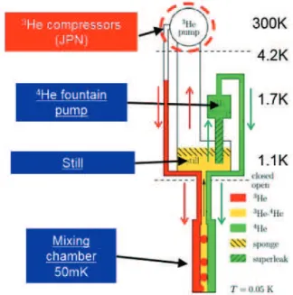
概念図を図3に示す。主要な要素技術としては、3
He循環ポンプ、4
He循環ポンプ、分留室、
約1.7 Kの予冷温度領域、熱交換器および混合室となっている。3
Heの気体–液体間の相分離は、
ソープション冷凍機などで実績のあるポーラススポンジを分留室に導入して行う[19]。4
Heは分
留室温度領域ではほぼ全て液体となっているが、この4
Heの循環には、ポーラスプラグを用い
て熱機械効果により超流動4
Heのみが循環するFounatain pump (FP)を用いる。かわって3 He
は分留室温度領域にてほぼ全て気体のため、室温に設けられた圧縮機を用いたガス循環が考え られる。
フランスのCNRS (Centre national de la recherche scientifique = フランス国立科学研究セ
ンター)を中心に行われたプロトタイプの実験では、60 mKにて1 µWの冷凍能力を作り出す
ことに成功した[17]。しかし本クローズドサイクルの実現には、1 kPa未満の低い吸込圧を作
り出す3
He 循環圧縮機が必要であること、1.5 K前後にて十分な冷凍能力を持った予冷機が必
要であることが指摘された。
1.
3
宇宙用クローズドサイクル希釈冷凍機の研究開発
上記のような背景を元に、研究開発部門では、1.7 Kを生成する1K級ジュールトムソン冷凍機
(1K-JT)よりもさらに低温である50 mKを生成する冷凍機として、クローズドサイクル希釈冷
凍機システムを、フランスのCNES (Centre national d’etudes spatiales = フランス国立宇宙研
究センター)、CNRSおよびAir Liquide社と協力して研究開発した[20, 21, 26]。各担当の要素
技術を図 4に示す。
クローズドサイクル希釈冷凍機の実現には、Planckで実現した技術に加え、超流動4
Heと 3
Heを分離する分留室 (Still)や超流動4
Heを循環するFountain pump、および3
宇宙航空研究開発機構研究開発資料 JAXA-RM-16-007
10
クローズドサイクル希釈冷 凍機の圧縮機開発および希 釈冷凍機システム評価試験
圧縮機が必要である。特に3
He圧縮機は、圧縮機開発が得意技術である日本の参加によって早
期実現が期待できることから、3
He圧縮機の研究開発を日本、分留室など低温部をフランスが
担当する形で協力して進められた。なお、このクローズドサイクル希釈冷凍機には、1.5∼1.8 K
程度の予冷温度が必要であり、1.7 Kを実現する日本の1K-JTを使用する前提で研究開発が進
められた[4]。
凍機の圧縮機開発および希 釈冷凍機システム評価試験
Figure 4: フランスと協力して進めるクローズドサイクル希釈冷凍機の概念図および各機関の担当部分。JP :日本
が新規開発を担当、FP :フランスが新規開発を担当。予冷温度1.7 Kおよび4.5 Kは、日本のジュールトムソン
2
クローズドサイクル希釈冷凍機システムの構成と目標性能
2.
1
希釈冷凍機の冷却原理
3
He-4
He希釈冷凍法の原理は以下の通りである。50 %濃度のHe同位体混合液を冷却していく
と、約1.3 Kで4
Heが超流動状態になり、約0.8 Kで3
Heのc相とd相に相分離され、さらに低
温ではc相は純3
Heに、d相は約6.6 %の3
Heを含んだ状態に近づく。ここで、d相の3
He溶解
量が絶対零度においても6.6 %持っている点が、100 mK未満の極低温において高い冷凍能力を
持つ希釈冷凍機を可能としている。3
He-4
He希釈冷凍機では、c相とd相が接しており、冷却生
成する部分は混合室(MC: Mixing Chamber)、相分離する部分は分溜室(Still) と呼ばれる。分
留室温度 (約0.8K)では、4
Heの蒸気圧はほぼ0で、3
Heの蒸気圧は有限のため、3
Heを選択的
に蒸発可能であり、d相の3
He濃度が平衡状態より低くなる事でc相からd相へ3
Heが溶解し、
この時のエントロピー差を利用することで、混合液から潜熱を奪って冷却が発生する。
あらためて図4を見てみる。混合室にて混合冷却された混合液は、分留室にて3
Heガスを多
く含む混合ガス(10 %程度の液体Heを含む90 %以上の3
Heガス)を選択的に3
Heポンプにて
蒸発循環させるようにし、かわって残りの4
HeはFP(Fountain Pump)によって循環される。
両者の循環配管は1K pot (図上 1.7 K部分) にて冷却され、更に分留室と熱交換した上で最終
的には混合室出口配管と熱交換され、混合室にて混合される。
以下に個々の要素の詳細を記す。まず混合室だが、地上のように重力を利用して、密度差に
よって冷却界面を生成する事は出来ないため、宇宙用では毛細管力を使用している[1, 17, 18]。
ヘリウム同位体をY型分岐管に通して1つの毛細管を通過させる際に、毛細管力が重力分離と
同じ役割を担い、d相とc相が分離される。その後、c相からd相への3
Heの移動に伴い冷却が
発生する。FPは、4
Heが超流動状態になる2.17 K 以下で駆動させ、分留室と接続されたスー
パーリーク間で低温側から高温側(FP本体) へと温度差分だけ超流動4
Heが流れる熱機械効果
を利用している。よって、4
He流量の大きさはヒータを用いたFP内温度差で制御される。1K
potは、本システム評価試験の地上技術実証では、4.2 Kの液体Heタンクと細管で接続し、減
圧することで蒸発冷却により1.3 K∼1.8 Kの温度を生成する。本温度領域は、実際の宇宙機で
は冷凍機にて予冷を行う予定で、1.7 Kを生成できる1K-JTが筆頭となる。分留室は、重力に
依存しない分離方法として、多孔質材の空隙の部分に毛細管力を用いて混合液を保持させてお り、3
He循環圧縮機が作り出す低圧力に合わせて、ヒータ熱負荷を制御することで最適な温度
を保つ。分留室内の典型的な圧力は0.5∼1.0 kPaで、温度は1.1∼1.3 K (希薄混合液中の3He濃
度が10 %以上)で最適な駆動状態となる。
上記の圧力を達成しつつ、希釈冷凍機の冷凍能力を決定する重要な要素が3
He循環圧縮機で
宇宙航空研究開発機構研究開発資料 JAXA-RM-16-007
12 凍機の圧縮機開発および希
釈冷凍機システム評価試験
機は存在しなかった。Planckで実証された技術に加えて、クローズドサイクル方式を実現する
ための新規技術としては、3
He循環圧縮機以外には分留室やFPとなり、これら低温部はフラ
ンスが担当している。3
He循環圧縮機については、2009年頃に欧州側が日本の冷凍機用圧縮機
に注目し、日本側が研究開発に着手した。
2.2
クローズドサイクル希釈冷凍機に求められる冷凍能力
次世代のX線天文衛星に搭載されるマイクロカロリメータは、原理的に動作温度でエネルギー
分解能 (カロリメータの最も重要な性能)が決まるため、「動作温度50 mK」という要求を満た
すことは必須となる。当然ながら接触熱伝導などにより、熱浴よりも検出器は若干高温となる
ため、冷凍機の要求生成温度は50 mKより低くなる。これより希釈冷凍機の目標温度は45 mK
となっている。
一方で冷凍能力については、カロリメータの自身の発熱は現実的な数字としてa few hundred
nW 1程度である。これに配線熱伝導を足してマージンを取った値が、50 mKに対する要求冷
凍能力となる。よって要求される冷凍能力は、予冷系温度に強く依存する。
希釈冷凍機は分留室 –混合室 (50 mK) 間の熱交換部に大きな吸熱能力があり、ここを検出
器配線系の熱アンカー部として利用することができるため、断熱消磁冷凍機と比べ、より小さ な冷凍能力で済むと予想される。
2.3
ヘリウム
3
循環圧縮機システムに求められる性能
クローズドサイクル希釈冷凍機用圧縮機に求められる性能としては、吸込圧および作動ガス流 量が最も重要である。本項では、フランス担当の低温部の冷却試験結果より、圧縮機に求めら れる吸込圧および流量について述べる。
2.3.1 初期の冷却試験 (F.Martin et al. Cryogenics 2010)[1]
図 5は、2010年にCryogenicsに掲載された希釈冷凍機の冷却試験結果における、各分留室内
圧力における到達温度と冷凍能力の関係である[1]。この希釈冷凍機プロトタイプは目標性能
が冷凍能力1 µW (50 mK)となっているため、この目標を満たすための分留室、混合室、FP、
Capillaryの設計となっている。
図5より、吸い込み圧673 Paの時に冷凍能力1µWが得られる到達温度は74 mKとなり、吸
い込み圧18 Paまで下げた時の冷凍能力1µWが得られる到達温度は57 mKとなっている。横
軸が0 K2の時にマイナスになっているのは、自身の熱負荷によるもので、この系ではParasitic
もちろん検出器の 数によるが、検討されている妥当な 数より参照。
1 もちろん検出器の
Figure 5: Experimental results of closed cycle dilution cooling tests in 2010 [1]. Blue : 18 Pa, Red : 322 Pa, Green : 673 Pa.
な熱負荷が1 µW程度あること、45 mK程度が最低到達温度(自身を冷やすだけで、冷凍能力
はない)であることが分かる。
Pstill n˙3 n˙4 Q1˙ .35K Qstill˙
(Pa) (µmol/sec) (µmol/sec) (mW) (mW) 322 16.4 127.2 3.05 0.71
673 14.7 85.4 2.10 1.03
18 11.2 134.1 2.52 0.18
Table 1: Experimental results of flow rate and estimated heatloads [1].
各吸込圧における、3
Heおよび4
Heの流量と1.35 K予冷器に対する熱負荷および分留室(still)
のヒータ熱負荷の関係を表1に示す。4.2 Kから1.35 Kまで3
Heを冷却するために奪うべき熱
量は0.5∼1 mWと見積もられるが、Q˙1
.35Kは明らかにこれよりも大きく、Fountain pumpから
の熱負荷を取り去るための予冷機がこの温度領域に必須であることが分かる。1KJTの生成温
宇宙航空研究開発機構研究開発資料 JAXA-RM-16-007
14 凍機の圧縮機開発および希
釈冷凍機システム評価試験
2.3.2 2011年のフランス側冷却試験結果
吸込圧が低いほど到達温度が低く冷凍能力が高くなる。2011年の冷却試験結果より、フランス
側が提示した性能は、
• 20µmol/sec (60µg/sec)以上、0.5 kPa
• 30µmol/sec (90µg/sec)以上、1 kPa
• 60µmol/sec (180µg/sec)以上、1.5 kPa
となった。これは冷凍能力1.6µW (45 mK)を目指した時の要求値と思われるが、ただし上
記の値は実験結果と詳細に比較すると少し足りない値に思われた。
2.3.3 2012年のフランス側冷却試験結果
上記とは別で、分留室圧力を変えた時の冷凍機性能の影響が調べられている。これによると
• <0.5 kPa : 冷凍機は分留室圧力に大きな影響を受けない。
• 0.5< Pstill< 1 kPa : 冷却性能が分留室圧力に合わせて劣化する。
• 1.0< Pstill< 1.5 kPa : 冷却性能が不安定。
となり、少なくとも0.8 kPa以下でなければ安定した動作をしない、と予想される結果と
なった。
2.3.4 要求吸込圧
上記の議論より、50 mKにて冷凍能力1µWを達成するためには吸込圧1 kPa あれば十分であ
る。一方で比較として、冷凍能力1.6µW (45 mK)を得るには、吸込圧30 Paでもかなり厳しい 条件であることが分かり、1 kPaでは1.0µW程度(45 mK)が限界と考えられる。
一方、冷却性能が分留室内圧力に大きく影響を受けないようにするためには、0.5 kPa以下
が必要であり、圧損を考慮すると圧縮機吸込圧は0.4 kPa以下が必要となる(2.3.3章参照)。
ただし要求される3
Heガス循環系の室温部吸込圧は、分留室の制御温度および熱交換部に使
用するCapillaryの直径と長さを含めた圧損に依存する。今後の設計改良によって、吸込圧によ
る冷凍能力依存性は改善される可能性がある。
2.3.5 要求作動ガス流量
希釈冷凍は、c相からd相へ流れ込む3
Heのエンタルピー変化によって吸熱反応を作り出す。こ
の時の冷凍能力Q˙mcは3
Heの流量n˙3に比例する。もしn˙3が十分ある場合、4
Heの流量n˙4が
冷凍能力を決めることになり、混合室温度Tmc を用いて、
˙
Qmc = 5.76 ˙n4T 2
mc (1)
と表される[1]。よって3
Heの流量が十分得られれば、直接は3
Heが冷凍能力に影響しなく
なる。
式 1が成り立つ時に50 mKにて必要なn˙4は、冷凍能力1 µWでは70 µmol/secとなる。 ただし実際の装置では25 %程度の不定性があり[1]、これを考慮すると冷凍能力1 µWでは 100 µmol/sec、1.6 µWでは160µmol/sec程度となる。n˙4を増やすにはFountain pumpのヒー
タ熱量を増やす必要があり、1 K温度領域の予冷系への熱負荷は増加する。
3
Heの流量n˙3は、大きく見積もってn˙4の20 %とすると、冷凍能力1 µWでは20µmol/sec (60 µg/sec)、1.6 µWでは32µmol/sec (96µg/sec)程度となる。
各生成温度および冷凍能力を要求した際に必要なn˙4およびn˙3の値を表2に示す。注意すべ きは、3
Heにとってはこれが「最低必要な」流量であり、これを下回ると冷凍能力が下がるだ
けでなく、3
Heが冷凍能力を決めることになり、同時にn˙3の安定度が冷凍能力の安定性に影響
を与えることになる。
Tmc Q˙mc n˙4 n˙3
(K) (µW) (µmol/sec) (µmol/sec)(µg/sec) 50 1.0 100 20(60) 50 1.6 160 32(96) 45 1.0 120 24(72) 45 1.6 183 37(111)
Table 2: 各生成温度および冷凍能力に対し必要とされる4
Heおよび3
Heの流量。
2.4
ヘリウム
3
循環圧縮機システムの目標性能のまとめ
上記より、ヘリウム3循環圧縮機システムに求められる吸込圧および作動ガス流量は以下にま
とめられる。これらの見当結果より、吐出圧力などを含め、ヘリウム3循環圧縮機システムの
目標性能は表 3のように設定された。
1. 冷凍能力1.0 µW (50 mK)の場合
クローズドサイクル希釈冷 凍機の圧縮機開発および希 釈冷凍機システム評価試験
(a) 吸込圧 要求0.8 kPa、目標0.4 kPa。
(b) 3
He流量 20µmol/sec (60µg/sec)以上
冷凍能力 の場合
吸込圧 でも厳しい。
流量 以上
目標性能 流量
吸込圧力 吐出圧力 駆動電力
ヘリウム 循環圧縮機システムの目標性能。
想定される冷凍機システム
クローズドサイクル希釈冷凍機 を用いた典型的な冷凍機システム。点線内が となる。
希釈冷凍機は原理的に、室温から 以下を直接生成できるものではなく、 未満ま
で予冷が必要である。前述のように、クローズドサイクル希釈冷凍機の場合、 程度
の予冷温度を別途生成する必要がある。
クローズドサイクル希釈冷凍機を用いた場合の、典型的な冷凍機システムを図 に示す。点 線で囲まれた部分が本研究開発のクローズドサイクル希釈冷凍機システムを表している。予冷
宇宙航空研究開発機構研究開発資料 JAXA-RM-16-007
16
凍機の圧縮機開発および希 釈冷凍機システム評価試験
吸込圧 要求 、目標 。
流量 以上
2. 冷凍能力1.6 µW (45 mK)の場合
(a) 吸込圧 30 Paでも厳しい。
(b) 3
He流量37 µmol/sec (111 µg/sec)以上
目標性能 流量(3
He) ≥33µmol / sec 吸込圧力 <0.4 kPa 吐出圧力 >20 kPa 駆動電力 <80.0 W
Table 3: ヘリウム3循環圧縮機システムの目標性能。
2.
5
想定される冷凍機システム
Figure 6: クローズドサイクル希釈冷凍機(CCDR)を用いた典型的な冷凍機システム。点線内がCCDRとなる。
希釈冷凍機は原理的に、室温から100 mK以下を直接生成できるものではなく、2 K未満ま
で予冷が必要である。前述のように、クローズドサイクル希釈冷凍機の場合、1.5∼1.8 K程度
の予冷温度を別途生成する必要がある。
クローズドサイクル希釈冷凍機を用いた場合の、典型的な冷凍機システムを図 6に示す。点
線で囲まれた部分が本研究開発のクローズドサイクル希釈冷凍機システムを表している。予冷
機としては1K-JTが必須と思われるが、実現性を考えると、侵入熱低減のために4K級ジュール
クローズドサイクル希釈冷 凍機の圧縮機開発および希 釈冷凍機システム評価試験
トムソン冷凍機 (4K-JT)も必要と思われる。それより高い温度の中間温度領域は、各ミッショ
3
ヘリウム
3
を循環する圧縮機システムの設計製作
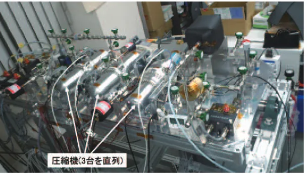
Figure7: クローズドサイクル希釈冷凍機用圧縮機システムの概念図。
圧縮機システムの研究開発は、1K-JT冷凍機用圧縮機をベースとして開始した。1K-JT冷凍
起用圧縮機の吸込圧力は8 kPaであり、宇宙用の圧縮機では最低圧力を有する。しかし、本研
究開発の目標とするヘリウム3循環圧縮機は更に1/10以下の吸込圧力を達成する必要があり、
非常に挑戦的な目標値という事がわかる。目標性能を達成するため、従来の圧縮比の実績(1段
あたり圧縮比4)から、圧縮段数として3段を選定した。特に重要となる1段目の低圧段圧縮機
においては、目標吸込圧力を達成するため、圧縮体積を大きくするために、従来よりも大幅に 大きい直径70 mmのピストンを使用した。一方で2段目 (中圧段)と3段目(高圧段)について
は、従来のジュールトムソン冷凍機用圧縮機で実績のあるピストン直径40 mmと25 mmの圧
縮機を用いた。圧縮機内部については、圧縮に要されないデッドボリュームの低減、圧力損失 低減、更には到達圧力や過渡的な応答に影響する吸気/排気バルブの厚み最適化等を実施する
事で性能改善を実施した。ヘリウム3循環圧縮機システムの概略図および外観を図 7と図 8に
宇宙航空研究開発機構研究開発資料 JAXA-RM-16-007
18 凍機の圧縮機開発および希
釈冷凍機システム評価試験
Figure8: 試作したクローズドサイクル希釈冷凍機用圧縮機システム。
選択可能となっている。その他のデータとして、低圧段圧縮機近傍の振動レベルを計測するた
めに、圧縮機駆動軸方向(X方向)の加速度の計測と各所の温度計測を実施している。本圧縮
機システムの希釈冷凍機低温生成部とのI/FはVJ1とVJ2になっており、VJ1が分流器側配
管と接続され、VJ2が混合器側配管と接続される。ヘリウム3循環圧縮機システムの計測機器
接続図を図 9に示す。ファンクションジェネレータにて生成した正弦波をバイポーラ電源にて
100倍に増幅し、電力計を介して圧縮機を駆動させている。データロガーでは上述の上記の圧
力,温度,振動レベルに加え、電力計で取得された電圧・電流・電力データ等の全部で29点の
宇宙航空研究開発機構研究開発資料 JAXA-RM-16-007
20 凍機の圧縮機開発および希
釈冷凍機システム評価試験
4
ヘリウム
3
を循環する圧縮機システムの性能評価
0 0.2 0.4 0.6 0.8 1
0 5 10 15 20 25 30 35 16 18 20 22 24 26 28
P inlet (kPa)
P outlet (kPa)
Flow rate (umol/sec) Target
Pinlet/Poutlet with 4He Pinlet/Poutlet with 3He
Pinlet/Poutlet with 4He and GHS
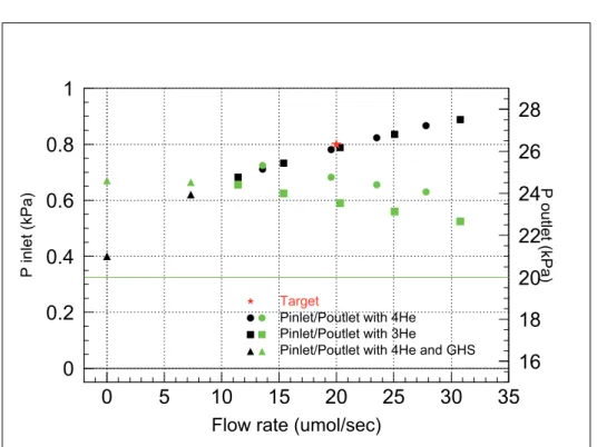
Figure 10: ヘリウム3循環圧縮機システムの単体評価試験結果。
試作したヘリウム3循環圧縮機システムについて、 表3に示した目標性能を満足するかの単
体性能評価試験を実施した。性能評価試験結果(3
He換算流量、吸込圧力Pinlet、吐出圧力Poutlet) を図 10に示す。4
He充填時を丸、3
He充填時を四角、フランス運搬後にフランス担当のガス制
御システムと接続しながら3
He充填時の測定結果を三角で示している。全て駆動条件はほぼ同
一である。3
He 充填時の方が小さな吐出圧力となっているが、これは熱物性差に起因する圧力
損失の違いによるものであると考えられる。一方、吸込圧力は三者で大きな変化が見られず、
約33µmol / secにおいて0.9 kPa程度となっており、目標性能を満足する結果は得られなかっ
た。充填圧力(小さいほど基本的には吸込圧力が低い)や駆動周波数(小さいほど電力は大きい
が吸込圧力が低い)等の性能に影響するパラメータを変化させても、吸込圧力は当初目標を満足
できなかった。その後、システム評価試験の実施可否に向けてフランス側と調整を行い、希釈
冷凍機が駆動できる可能性がある性能として、表 4に示すように新たな目標性能の設定を行っ
た(図 10の星のプロット)。これに対しては満足する結果が得られたため、本単体試験結果をも
とにシステム評価試験を実施する事とした。なお、駆動電力は35 Wと、目標である80 W未
満を十分満足する事も確認できた。
16 18 20 22 24 26
0 100 200 300 400 500 600 700
(kPa), (C
o )
Time (min)
0 1 2 3 4 5 6
0 100 200 300 400 500 600 700
(10x umol/sec), (kPa)
Time (min)
Figure 11: ヘリウム3循環圧縮機システムの単体評価試験結果。約10時間駆動した時の時間変化。赤 :圧縮機
テーブル温度、青:吐出圧力、黒:3
He換算流量、緑:吸込圧力、紫:低圧段圧縮機–中圧段圧縮機間の圧力、水
色: 中圧段圧縮機–高圧段圧縮機間の圧力。
目標性能 試験結果
流量(3
He) ≥20µmol / sec 20µmol / sec
(≥32µmol / sec)
吸込圧力 <0.8 kPa (<0.4 kPa) 0.79 kPa 吐出圧力 >20 kPa 21 kPa
充填圧力 - 2.8 kPa
駆動電力 <80.0 W
Table 4: ヘリウム3循環圧縮機システムの単体試験結果。 クローズドサイクル希釈冷
凍機の圧縮機開発および希 釈冷凍機システム評価試験
測定結果を図 11に示す。駆動を開始してから約5時間かけて、圧縮機の発熱により圧縮機を
宇宙航空研究開発機構研究開発資料 JAXA-RM-16-007
22 凍機の圧縮機開発および希
釈冷凍機システム評価試験
5
希釈冷凍機システムのシステム評価試験
Figure 12: システム評価試験のセットアップの様子。
2015年4∼5月にかけて、フランス グルノーブルにあるCNRSニール研究所にて、日本担当
のヘリウム3循環圧縮機システムとフランス担当の低温部を結合したシステム評価試験を実施
した。フランス担当低温部との結合後の試験装置の概観図を図 12に、低温部におけるデータ
取得位置を図13に示す。システム評価試験は下記の3段階に分けて試験を実施した。
1. Test 1 : 70 mK維持状態にて地上用ポンプから切り替える。
2. Test 2 : 低温部 1 Kから希釈冷凍で冷却。
3. Test 3 : 低温部 18 Kから希釈冷凍で冷却。
本システム評価試験で使用したフランス担当の低温部は、混合室への侵入熱などにより、地
上用の循環ポンプを用いた場合でも最低到達温度は70 mKてあった。よって、システム評価試
験としては、70 mKの到達維持が一つの指標となった。
5.1
Test 1 : 100 mK
にて
Helium-3
循環運転を地上用循環
pump
から圧
縮機へ切り替え
まずは、試作したヘリウム3循環圧縮機システムを用いた場合の希釈冷凍の性能への影響を最
Figure 13: 希釈冷凍機システムの低温部の温度計設置箇所および熱負荷入力箇所。4He流路を緑、3He流路を赤、
混合ガス流路を黄色で表す。MCが混合室。重力を用いずに動作することを実証するため、混合室は分留室(still)
より上部に位置している[20]。
Tmo Tpot 3He flow rate Pinlet Poutlet (mK) (K) (µmol/sec) (PL)(kPa) (PH)(kPa)
2nd May 70 mK 1.34 K 22 0.8 kPa 12 kPa 6th May 70 mK 1.34 K 38.9 0.92 kPa 8.4 kPa 9th May 70 mK 1.34 K 25 0.83 kPa 6.7 kPa 12th May 70 mK 1.71 K 31 0.9 kPa 12 kPa 13th May 70 mK 1.71 K 34 0.9 kPa 12 kPa
宇宙航空研究開発機構研究開発資料 JAXA-RM-16-007
24 凍機の圧縮機開発および希
釈冷凍機システム評価試験
試験結果を表 5に示す。本試験時の熱浴温度 = 1K potの温度(図 13のTpot)は、希釈冷凍に とって比較的有利な条件である1.34 Kと、1K-JTが生成可能な温度の指標として1.71 Kの2
種類行なった。結果として、計5回の試験で全て正常に動作し、70 mKを維持できることが確
認された。
5.
2
Test
2 : 1 K
以上から冷却
Test 1の次のステップとして、混合室が1 K程度の状態から、ヘリウム3循環圧縮機システム
を用いて希釈冷凍により100 mK以下を生成するTest 2を行なった。こちらも1K pot温度が
1.34 Kと1.71 Kの場合の2種類の条件で試験し、数回のパラメータ調整を経て、問題無く冷却
できることを確認した。
5.
3
Test
3 : 1
5
K
以上から冷却
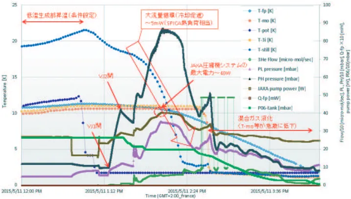
Test 3の冷却プロファイルを図 14∼ 16に示す。本冷却過程は、実際の衛星の冷凍機システム
のように、常温から冷却していく過程を短い期間で確認するための模擬試験となっている。冷 却プロセスとしては、低温部全体を18 K近傍まで昇温させた後、1K potが1K-JTで直接冷却
されている状態を想定し、ヘリウム3循環圧縮機システムにて内部混合ガスを大流量で循環さ
せ、1K pot と熱交換を行わせながら低温部を冷却していく。本試験では、冷却時間を短縮す
るため、ガス制御システムにて混合ガス保管タンクから冷媒である3
Heガスを数回に分けて低
温部に充填しつつ、流量を可能な限り大きくするようにしている。この際の1K potへの熱負
荷は5 mW以下となっており、1K-JT冷凍機の冷凍能力10 mW at 1.7 Kの範囲内となってい
る。上記の操作により、低温部は約3時間で1K pot温度と同程度の2 K以下を達成している
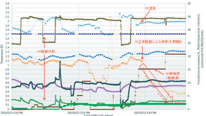
(図 14)。2 K以下になった後は、FP駆動のために混合ガス量を再度調整した後、FPに熱負荷
を与え駆動させて、希釈冷凍機の駆動を行っている(図 15)。FPが安定的に駆動し始め、希釈
冷凍機が駆動した後は、混合ガスのさらなる濃度調整を行なって最適な状態を作り出し、低温 端の到達温度が低くなるようにしている(図 16)。結果として、Test 3でも約12時間で70 mK
の到達が確認された。
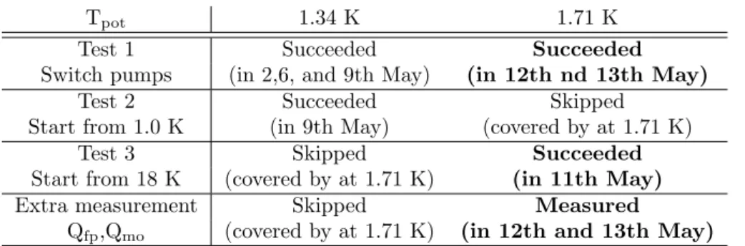
表 6にシステム評価試験結果を示す。全体として、目標としていた、1K pot温度が1.34 K
での希釈冷凍機の駆動のみならず、希釈冷凍機低温部の単体試験でも実施していなかった予冷
温度1.71 Kにおいても、軌道上環境での常温からの冷却を模擬した18 Kからの冷却にて、希
釈冷凍機が駆動して約70 mKに到達できる事を確認し、当初予想していた以上の成果を得る事
ができた。
混合室に熱負荷を与えることで冷凍能力が測定された。Parasiticな熱侵入量は3.3 µWの見
宇宙航空研究開発機構研究開発資料 JAXA-RM-16-007
26 凍機の圧縮機開発および希
釈冷凍機システム評価試験
Figure 15: Test 3のシステム評価試験結果(1 Kから0.3 Kへ冷却)。
おける冷凍能力は、4
He流量が236 µmol/secの状態で3.5 µWと導出され、こちらも理論的に
予想される値とほぼ一致する結果となった。
Tpot 1.34 K 1.71 K
Test 1 Succeeded Succeeded
Switch pumps (in 2,6, and 9th May) (in 12th nd 13th May)
Test 2 Succeeded Skipped
Start from 1.0 K (in 9th May) (covered by at 1.71 K)
Test 3 Skipped Succeeded
Start from 18 K (covered by at 1.71 K) (in 11th May)
Extra measurement Skipped Measured
Qfp,Qmo (covered by at 1.71 K) (in 12th and 13th May)
Table 6:クローズドサイクル希釈冷システム評価試験結果のまとめ。
凍機の圧縮機開発および希 釈冷凍機システム評価試験
6
まとめ
宇宙用クローズドサイクル希釈冷凍機の実現に向け、重要構成要素であるヘリウム3循環圧縮
機システムの開発を行い、圧縮機の性能に対する駆動周波数、充填圧力、充填ガス(3He, 4He)
の影響が確認できた。また、圧縮機内部の圧力損失等により、当初目標としていた吸込圧力を 達成出来なかったものの、フランス担当の低温部の駆動に必要な流量および圧力を得ることが できた。上記の成果をもとに実施した、フランスが研究開発中の低温部と結合してのシステム 評価試験では、1K pot温度が1.71 K(1K-JT冷凍機生成温度)の状態で、低温部が18 Kの状
態から冷却を行い、希釈冷凍を駆動させ、最低到達温度70 mKを達成し、世界初のクローズド
宇宙航空研究開発機構研究開発資料 JAXA-RM-16-007
28 凍機の圧縮機開発および希
釈冷凍機システム評価試験
A
システム評価試験ログ
1. 2nd May 2015
(a) First trial of the test 1 at Tpot of 1.34 K (succeeded). (b) First trial of the test 2 at Tpot of 1.34 K (not succeeded).
2. 6th May 2015
(a) Second trial of the test 1 at Tpot of 1.34 K (succeeded). (b) Second trial of the test 2 at Tpot of 1.34 K (not succeeded). 3. 9th May 2015
(a) Third trial of the test 1 at Tpot of 1.34 K (succeeded). (b) Third trial of the test 2 at Tpot of 1.34 K (succeeded).
4. 10th May 2015
(a) First trial of the test 3 at Tpot of 1.33 K (not succeeded).
5. 11th May 2015
(a) Second trial of the test 3 at Tpot of 1.71 K (succeeded). (b) The optimization trial of3
He / 3
He ratio at 70 mK.
6. 12th May 2015
(a) Fourth trial of the test 1 at Tpot of 1.71 K (succeeded). (b) The cooling power measurement using Qmo at Tpot of 1.71 K.
(c) The inlet pressure measurement at Tpot of 1.9 K.
7. 13th May 2015
(a) Fifth trial of the test 1 at Tpot of 1.71 K (succeeded). (b) The Qfp measurement at Tpot of 1.71 K.
closed-cycle dilution refrigerator system”,
30th International Symposium on Space Technology and Science,
Development of helium-3 compressors and
integration test of closed-cycle dilution
refrigerator system
K.Shinozaki
1), K.Sawada
1), Y.Sato
1), H.Sugita
1), K.Mitsuda
2),
T.Nakagawa
2), S.Tsunematsu
3), K.Narasaki
3), G.Vermeulen
4), P.Camus
4),
S.Triqueneaux
4), S.Martin
5), S.d’eEscrivan
6)1) JAXA/ARD, Japan 2) JAXA/ISAS, Japan
3) SHI ltd., Niihama works, Japan 4) Institute Neel, CNRS/UJF, France 5) Air Liquide Inc., France
6) CNES, France
International Symposium on Space Technology and Science, 10thJuly 2015, Kobe, Japan
1
2
1. Introduction
50mK low temperatureis needed to reduce a thermal fluctuation noise and realize a superior sensitivity instrument, which revolutionizes our understanding of space science and carries a new horizon in space.
Several field’s space science missions propose to use low temperature instruments.
X-ray astronomy: Astro-H (to be launched), Athena, DIOS Infrared astronomy: SPICA
CMB observation: Planck (launched on 2009), LiteBIRD
There are two methods to make below 100mK:
Adiabatic Demagnetization Refrigerator (ADR): High thermal efficiency, recycling time (no observational time) is needed, high magnetic field.
Dilution refrigerator: continuous cooling, no magnetic field, low technical level. Cooling chain from 300K to 50mK is also important.
Energy (keV)
C
ount
s
(arbit
rar
y
unit
)
3
Launched by Ariane V on May 2009
2ndLagrangian orbit
40K cooled telescope (1.5m, 30~900GHz) 2 scientific instruments: LFI (20K), HFI (0.1K)
The open cycle dilution refrigerator (OCDR) – (France)
1stdilution refrigerator in space.
Space pump working gas (helium).
3He as well as 4He were extracted.
Cooling power of only 100nW at 100mK. 12000 L of 3He and 36000 L of 4He.
2 year’s operation.
Closed cycle dilution refrigerator for future mission.
3He / 4He To space 3He
tank
4He tank
S.Triqueneaux et al. Cryogenics v46 (2006)
4
2. Objective of the development
Closed cycle dilution refrigerator (CCDR) is desired for next generation space science mission.
Higher cooling power.
Operational temperature (<100mK) continuously. No magnetic field.
Lower mass and more compactness than other cooling methods.
Target: Athena, LiteBIRD, DIOS, etc..
Cooling power: 1μW at 50mK
Lifetime: 5 years (requirement)
The helium-3 compressor is needed to circulate the helium-3 gas. The space qualified low pressure compressor had been successfully developed for 1K-class Joule Thomson cooler in Japan. Therefore, the helium-3 compressor system for CCDR has been developed in Japan, as a new challenge of a R & D collaboration between France and Japan in the space development.
Then, we tried to have the coupled testbetween the helium-3 compressor system and the cold part developed by France (CNES/CNRS/Air Liquide).
3. CCDR system
5
1.1K Still(FR)
Separate 3He from
mixture using different saturated P.
Mixing chamber
(FR)
50mK operation
CCDR schematic drawing
Planck heritage
300K
3He compressors (JP)
To circurate 3He from
still to heat exchanger
1.7K 1K-JT Heat sink 4.5K 4K-JT Heat sink 1.7K
4He fountain pump
(FR) Circulate superfluid
4He with porous plug
What is a dilution refrigerator ?
There are two separated phases at low temperature mixing chamber in principle. 3He rich phase (c-phase) and 3He / 4He mixture (d-phase).
Cooling reaction is provided by a transfer of 3He from c-phase to d-phase.
The capillary force is used to separate two phases under microgravity (Planck heritage), while a gravitational force is used in ground.
A 3He compressorsas well as a still and a 4He pump have to be
developed.
Because of each technological level,
international collaboration is one of best choice.
Pre-cooler is needed. The use of 1K-class / 4K-class JT cooler
developed by Japan are proposed. 50mK
4. Cryo-cooler system including CCDR
6 2ST 2ST 4K-JT 1K-JT Heat exchanger
4He pump
300K
4.5K heat sink
1.75K heat sink
Mixing chamber
Still
1.1K
50mK Proposed cooler system
※Dashed line includes CCDR 3He compressor
Being developed in JAXA Completely developed in JAXA
Being developed for CCDR in CNES/CNRS
Heritage of Planck mission (developed in CNES/CNRS)
Development should be proceeded by considering all over cryo-cooler system on an equal relationship between JAXA and CNES / CNRS.
Pre-coolers are 4K-JT and 1K-JT cooler as a prior condition of cryo-cooler system in the CCDR study.
Division of study
• JAXA : 3He compressor, 4K-JT and 1K-JT cooler
• CNES / CNRS : 4He pump, Still, Mixing chamber, 4He / 3He circuit
7
Size 20cmφ diameter ×50cm length
per compressor
Prior condition
Mass Lower than 25kg Prior condition
Operating Temp 273 ~ 303 K Prior condition, equal to
1K-JT/4K-JT
Driving freq. 10 ~ 70Hz Prior condition
Input power < 80W (AC) in total Prior condition
Operating life time > 0.5 year (5 year in future development)
Constraint condition, for the test model
Inlet Pressure < 0.8kPa (<0.4kPa as a goal) Constraint condition
Outlet pressure > 20kPa Constraint condition
Mass flow rate >20μmol/sec (>33 as a goal) Constraint condition
Operating gas Helium-3 (Helium-4 is used in
HE3C performance measurement)
Constraint condition
Can be operated in vacuum
Space qualified is considered
8
6. Key parameters of the
3He compressors
development
Pressure target
The heritage of the development of 1K-class Joule Thomson cooler (1K-JT) provided a level of advantage. However, these target performances in particular low inlet pressure (0.8kPa) was challenging issues even when the heritage of 1K-JT was used.
Compression ratio and number of compressors
When actual performance of JT coolers are considered, typical compression ratio of each compressor is 4. Therefore, 3 compressors are needed for the targeted ratio of over 25 in total.
Contamination
Cleanliness level has to be carefully checked for the concern of failure in compressors as well as an iceplug.
Others
Resolution of pressure and flow rate measurement. Operation sequence.
Target Flow rate* Required
7.
3He compressors system design
H3
CL
H3
CM
H3
CH
3 compressors in series for 3-stage compression.
4 pressure gauges are installed between inlet / outlet pressure of 3 compressors.
The mass flowmeter is located to outlet to prevent the pressure loss, while the mass flow can not be measured with lower than 1kPa.
Getter and filter are assembled in parallel for contamination issue. VJ1 is the I/F of inlet line, while VJ2 is used for outlet line.
9
10
Transportation and preparation
Tsukuba Space Center, Tsukuba, Japan
11
Measured inlet pressures are quite similar even when charged pressure was changedfrom1 to 3kPa as well as from 4He to 3He, while outlet pressure is not
changed. This means that a leak and pressure drop prevents the performance. The measured outlet pressure with 3He is different from 4He, which is mainly
caused by different charged pressure.
Time (Hour)
9. Coupled test results
12
Goal of the coupled test
To achieve lower than 100mK.
To demonstrate the feasibility of cooler system with CCDR, in which cooling power of 1μW at 50mK.
Coupled test result
3He compressors has to be operated to circulate the working gas in order to cool down the mixing chamber, still and 4He pump from higher than 10K.
We could obtained 70mK from 18K with the heat sink of 1.75K
(K)
(hour)
Condense He mixture
70mK achieved by dilution process
-3He flow rate (10×μmol/sec) -Inlet P (kPa)
-Outlet P (kPa)
-Heat sink (K) -Still (K)
-Mixing chamber (K)
Time (Hour)
(K)
(10
×
μm
ol/
sec
, k
Pa)
Start the 3He
compressors
Summary
13 The 3He compressors system has been developed until 5 years (from 2009) for
a helium-3 circulator of closed cycle dilution refrigerator, as a new challenge of a R & D collaboration between France and Japan in the space development.
We have successfully achieved the preparation for the coupled test : I/F definition, construction of measurement system with safety function, transportation, and HE3C performance measurement.
Higher than 20μmol/sec of 3He flow rate has been obtained at the inlet pressure
of 0.8kPa in the 3He compressors system single performance measurement.
We also confirmed that the compressors system performance after
transportation to Grenoble is almost consistent with the performance in Japan.
The coupled test has been obtained 70mK from 18K by circulating the working gas with the 3He compressors system under the heat sink temperature of 1.75K.
refrigerator system
By Keisuke SHINOZAKI1), Kenichiro SAWADA1), Yoichi SATO1), Hiroyuki SUGITA1), Kazuhisa MITSUDA2), Takao NAKAGAWA2), Shoji TSUNEMATSU3), Katsuhiro NARASAKI3), G´erard VERMEULEN4), Philippe CAMUS4), S´ebastien
TRIQUENEAUX4), Sylvain MARTIN5)and St´ephane D’ESCRIVAN6)
1)Research Unit II, Research and Development Directorate, JAXA, Tsukuba, Japan 2)The Institute of Space and Astronautical Science, JAXA, Sagamihara, Japan
3)Sumitomo Heavy Industries, ltd. Development section, Industrial Equipment Division, Niihama works, Japan 4)Institute Neel, CNRS/UJF, Grenoble, France
5)AirLiquide Inc., Grenoble, France 6)CNES, Toulouse, France
The closed-cycle dilution refrigerator for space application is an on-going development to improve the performance of the open-cycle dilution refrigerator successfully used on the Planck mission. This solution has been considered in various projects in X-ray and far-infrared space instruments for astrophysics (ATHENA, SPICA) and in advanced studies for future CMB polarization surveys (LiteBIRD). It is shown that for sub-Kelvin applications, this refrigerator is fully competitive with some ADR-based solutions.
The helium-3 circulator is a key component to achieve the closed-cycle dilution refrigerator. JAXA and SHI have developed such a compressor by adapting the compressor of the space qualified 1K-class Joule-Thomson cooler. A coupled test of this compressor in combination with the dilution refrigerator developed by CNRS, Air Liquide and the CNES have been performed. In this paper, details of the target, design and circulation performance of the compressor system are shown. The result of first integration is also described.
Key Words:Dilution, Refrigerator, closed cycle, compressor, low temperature
1. Introduction
Low temperature instruments are major means for superior sensitivity in science observational missions. Recently, 100 mK or lower temperature is desired to obtain a high sensitivity and a high resolution spectroscopy (Athena, SPICA, LiteBIRD, etc.).1) 2) 3) 4)A closed cycle dilution refrigerator is a key
tech-nology to cool down to be 50 mK with a higher cooling power and a longer life time in comparison with existing coolers in space. This is an advanced design based on the open cycle di-lution refrigerator mounted in Planck satellite,5) 6)and created
a breakthrough in the space dilution refrigeration. In this de-sign,3He gas is needed to circulate as a closed cycle instead
of rejecting into space, which provides higher flow rate without no limitation of life time determined by amount of gas in the storage tank.
As a current target, longer than 5 years of life time with cool-ing power of 0.5∼1µW at 50 mK is expected. These target are consistent with requirements in current proposed missions. To achieve this, a space qualified helium-3 circulator is needed as a new important technology, and the low pressure compressor for 1K-class Joule Thomson cooler is one of primal candidate.7)
Then, a helium isotope separator in a still and a fountain pump to circulate a superfluid4He at low temperature are also needed.
2. Conceptional design of the closed-cycle dilution re-frigrator
Fig. 1 shows helium circulation lines of the closed cycle di-lution refrigerator.8) 9) 10) The key idea of the closed cycle di-lution process is to inject and mix both helium isotopes through
two capillaries in a Y-junction, and recover the mixture through a third capillary. As low temperature (<0.1 K), the dilute phase has a finite solubility of3He of 6.6 %. If the3He
concentra-Fig. 1. The schematic drawing of the closed-cycle dilution refriger-ator. The helium-3 is extracted by pumping with3He compressors on the gaseous phase much richer in3He (>90 %) than the liquid phase (∼10 %) and re-condensed into the still and mixing chamber.
tion exceeds this value, not all3He is diluted, but some stays
in the3He-rich phase forming3He droplets. The cross section
of the capillary is designed to be filled by these3He rich phase
droplets where the capillary forces play the role of gravity. The saturated liquid mixture produced in the mixing cham-ber enters the counter flow heat exchanger to precool the in-coming3He before returning into the still. The4He is extracted
from the still through a superleak by means of a fountain pump, which can only work below the superfluid transition tempera-ture. The3He is extracted by pumping on the gaseous phase
much richer in3He (> 90 %) than the liquid phase ( ∼ 10 %)
and then re-condensed into the dilution. In zero gravity con-ditions, the vapor liquid phase separation must be achieved in a porous material confining the liquid phase into the still. It is possible to obtain the cooling performance of closed cycle dilu-tion refrigerator with a still pressure in the range 0.5∼1.0 kPa.
This relaxes the requirements of the3He circulator compared to a classical dilution refrigerator.
From the technological point of view, the design of mixing chamber including Y-junction has a heritage of Planck mis-sion.5) 6) We have performed the test successfully with an
upside-down version of the closed cycle dilution refrigerator including the mixing chamber, still and fountain pump. The construction and tests of the upside-down dilution refrigerator are still unpublished. Then, a helium-3 circulator is a critical component to realize the space dilution refrigerator and should be obtained a realistic performance of the cooler with it.
When a cooling chain using the closed cycle dilution refrig-erator is considered for a space mission, a temperature and a cooling power needed for pre-coolig is also important. One pri-mal candidate as a pre-cooler is a 1K-JT, which provides the cooling power of 10 mW at 1.7 K. Therefore, 1.75 K is targeted as a heat sink of a3He circulation line and a fountain pump,
and the rejected heat into the pre-cooler, mainly generated by a fountain pump must be lower than 10 mW.
3. The target of the helium-3 circulator performance
The most important design parameter of the circulator is the inlet pressure Pinlet, which determines the operation temperature
of a still and also has an influence to a helium-4 circulation. As a first trial, the target Pinlet of 0.4 kPa was determined based
on the result of the closed-cycle dilution experiment using the commercial scroll pump. A pressure drop of 0.1 kPa was as-sumed between an interface of the circulator and the cold part in this target. In principle, a cooling power is determined by a
4He flow rate as a function of a temperature at a mixing
cham-ber when3He flow rate is enough. Tab. 1 in Chaudhry et al 9)
shows that a4He flow rate of 350mumol/sec is needed to obtain a cooling power of 1µW at 47 mK for a3He circulation rate of 28.8µmol/sec at a still pressure of 10 kPa. Therefore, the tar-get flow rate of3He has been 100µg/sec (33µmol/sec) in this study. Then, the outlet pressure of 20 kPa has been detemined as a target based on the experiments of the cold part.
The compressors design was based on the compressor devel-oped for 1 K-class Joule Thomson cooler (1K-JT).7)Though
the inlet pressure of 8 kPa for the 1K-JT is assumed to be the lowest pressure provided by space qualified compressor, it is still challenging that the inlet pressure design must be improved
to achieve 1/10 lower target inlet pressure.
In this design, 3 stage compression was determined using 3 units of compressors in series. 70 mm piston diameter was used to reach the enough flow rate for low pressure compressor (H3CL), while 40 mm and 25 mm piston diameter were used for middle and high pressure compressors respectively. New suction/discharge valves with thin spring were installed for all compressors.
Fig. 2 and 3 show the helium-3 circulator test model. Cool-ing fans are located close to each cylinder of compressors. The mass flow meter is installed after the outlet port of the high pres-sure compressor to prevent the influence of the prespres-sure drop in it. A high resolution pressure transducer MKS 690A is used to measure the inlet pressure, while MKS 121A pressure transduc-ers are used for three other pressure. A getter and a gas filter to reject an impurity and particle in the working gas are installed in parallel.
VJ1 and VJ2 valves are used to connect the gas handling sys-tem and dilution cold part. The performance test of the helium-3 circulator is measured independently by closing these valves and the performance with different flow rate can be measured with the throttle valve located between these interface valves.
Fig. 2. The schematic drawing of the helium-3 circulator using 3
units of compressors. Mass flow meter is located close to outlet port of high pressure compressor. A getter or a particle filter can be selected in the circulation line.
![Figure 1: 断熱消磁冷凍機 (単段式) の概念図。 た。また、宇宙用として近年では多段式 ADR が主流になりつつある。2016 年に打ち上げられ た日本で 6 番目の X 線天文衛星ひとみには、上記の半導体マイクロカロリメータの冷却のため に 3 段式 ADR が搭載され、軌道上にて 50 mK の生成に成功している [9, 10, 11]。また、多段 式の各段の冷却サイクルを交互に行い、連続的に 100 mK 以下を作り出す連続型 ADR が研究 開発されている [12]。これにより、リサイクル](https://thumb-ap.123doks.com/thumbv2/123deta/8209148.370786/6.892.300.597.177.463/なりつつ打ち上げマイクロカロリメータサイクルリサイクル.webp)
![Figure 2: 宇宙背景放射観測衛星 Planck に搭載された Service module から検出器ボロメータまでの冷却システム [13]。](https://thumb-ap.123doks.com/thumbv2/123deta/8209148.370786/7.892.243.656.206.506/Figure宇宙背景放射観測衛星搭載から検出ボロメータまで冷却システム.webp)
![Table 1: Experimental results of flow rate and estimated heatloads [1].](https://thumb-ap.123doks.com/thumbv2/123deta/8209148.370786/12.892.273.619.699.791/table-experimental-results-flow-rate-estimated-heatloads.webp)
![Figure 13: 希釈冷凍機システムの低温部の温度計設置箇所および熱負荷入力箇所。 4 He 流路を緑、 3 He 流路を赤、 混合ガス流路を黄色で表す。MC が混合室。重力を用いずに動作することを実証するため、混合室は分留室 (still) より上部に位置している [20]。](https://thumb-ap.123doks.com/thumbv2/123deta/8209148.370786/22.892.298.601.216.647/FigureシステムおよびHe流路混合ガス流路黄色表すMC動作するため混合.webp)