Finite Element Analysis for Advanced Stitched Composite of Partial Wing Structure for Next Generation Aircraft
(次世代航空機用先進縫合複合材部分構造翼の有限要素解析)
Prabij Joshi
DIVISION OF AEROSPACE ENGINEERING GRADUATE SCHOOL OF SYSTEM DESIGN
TOKYO METROPOLITAN UNIVERSITY
SEPTEMBER 2017
Finite Element Analysis for Advanced Stitched Composite of Partial Wing Structure for Next Generation Aircraft
(次世代航空機用先進縫合複合材部分構造翼の有限要素解析)
by
Prabij Joshi Student ID 13991575
Submitted to the Division of Aerospace Engineering, Graduate School of System Design,
in partial fulfillment of the requirements for the degree of Doctor of Philosophy in Aerospace Engineering
at
TOKYO METROPOLITAN UNIVERSITY September 2017
Certified by advisor
Professor Naoyuki Watanabe Division of Aerospace Engineering Graduate School of System Design
Tokyo Metropolitan University
Doctoral thesis committee:
Professor Naoyuki Watanabe Tokyo Metropolitan University (Chairman)
Professor Koichi Kitazono Tokyo Metropolitan University
Professor Satoshi Kobayashi Tokyo Metropolitan University
Professor Toshio Ogasawara Tokyo University of Agriculture and Technology
Abstract
Japan Aerospace Exploration Agency (JAXA) has designed and developed advanced composite wing. The experimental specimen has a unique design of 5000 mm length, in which stitch composite has been used on the front spar of 2000 mm length. The objective of this dissertation is to perform numerical analysis of the stitched composite structure of partial advance composite wing for displacement and strength analysis under static condition. To achieve this goal, step by step analysis has been carried out from coupon level to component level. Progressive failure analysis to study the effect of stitch with different densities and orientation has also been a great interest.
The effects of stitching are analyzed under in-plane tensile loading based on continuum mechanics. To obtain the macroscopic damage and the local stress–strain constitutive behavior, laminates were modeled on a lamina-wise basis. Interfaces between lamina and stitch yarns were assumed to be perfectly glued and modeled by the contact capability.
Progressive failure analysis with Puck’s failure criteria was conducted to characterize the failure behavior of the laminate.
Densely stitched laminates showed higher in-plane stiffness than moderately stitched laminates by suppressing the damage initiation. Open-hole longitudinally stitched laminate showed a better strength compared to the open-hole transversely stitched laminate by suppressing damage propagation on particular direction. Stress concentration factor was reduced by for longitudinal and transverse stitched laminates respectively, compared to unstitched open-hole laminates. Stitched laminates on front spar has been analyzed for damage characterization. Wing structural analysis has been done for the designed loadings. Proposed numerical analysis of various stitched laminates is capable of characterizing fracture propagation efficiently and accurately at a macroscopic structural. This technique has been capable enough to predict the displacement and stiffness of the stitched composite structure. Implementations of stitched laminates on wing structure give robust structure and aerodynamic improvement.
Keywords: damage, strength, stiffness, stress concentration factor, composite wing
ii
iii
Table of Contents
Abstract ... i
Table of Contents ... iii
List Of Figures ... v
List Of Tables ... viii
Nomenclature ... ix
Chapter 1... 1
Introduction ... 1
1.1.Background ... 1
1.2.Macro-Scale Modeling For Structural Analysis ... 3
1.2.1 Damage Characterization Of Stitched Laminates ... 5
1.2.2 Open-Hole Stitched Laminates ... 6
1.2.3 Composite Wing Structure ... 8
1.3.Problem Statements and Objectives ... 9
1.4.Overview Of The Thesis ... 10
Chapter 2... 14
Finite Element Formulation ... 14
2.1.Finite Element Formulation For Lamina and Stitch ... 14
2.1.1 Continuum Mechanics At Lamina ... 14
2.1.2 Continuum Mechanics Formulation For Contact ... 15
2.2.Contact Modeling ... 20
2.3.Failure Criteria ... 27
2.4.Failure Index and Strength Ratio ... 30
2.5.Analytical Stress Concentration Factor ... 33
Chapter 3... 36
Damage Characterization Of Stitch Laminates On Varied Densities ... 36
3.1.Introduction ... 36
3.2.Specimen and Test Details ... 37
3.3.Macroscale Finite Element Modeling Approach ... 39
3.4.Results and Discussions ... 45
3.4.1 Damage Characterization ... 45
3.4.2 Laminate Behaviour ... 50
3.4.3 Stress-Strain Behaviour ... 55
iv
3.4.4 Average Transverse Crack Density ... 56
3.5.Conclusions ... 59
Chapter 4... 61
Damage Characterization Of Open-Hole Stitch Laminates Based On Orientation ... 61
4.1 Introduction ... 61
4.2 Specimen and Test Details ... 62
4.3 Macro-Scale Modeling For Structural Analysis ... 64
4.4 Result and Discussions ... 71
4.4.1. Progressive Failure Analysis ... 71
4.4.2. Stress-Strain Behavior ... 75
4.4.3. Stress Concentration Factor ... 79
4.4.Conclusion ... 80
Chapter 5... 82
Numerical Analysis Of Partial Composite Wing Structure ... 82
5.1 Introduction ... 82
5.2 Experimental Analysis ... 83
5.3 Finite Element Approach Of Composite Wing Structure ... 90
5.3.1 Finite Element Modeling ... 90
5.3.2 Finite Element Modeling Of Assembly ... 95
5.3.3 Finite Element Loading and Boundary Conditions ... 102
5.4 Result and Discussions ... 104
5.4.1 Front Spar Deflection ... 104
5.4.2 Progressive Failure Analysis Of Stitched Composite Spar ... 109
5.4.3 Wing Deflection ... 110
5.4.4 Wing Assembly Through Contact Simulation ... 114
5.5 Conclusions ... 115
Chapter 6... 117
Conclusion and Recommendation ... 117
6.1 Conclusions ... 117
6.2 Recommendations ... 120
References ... 121
Publications and Conference Presentations ... 129
Appendix A ... 131
Acknowledgement ... 137
Bibliography ... 138
v
List of Figures
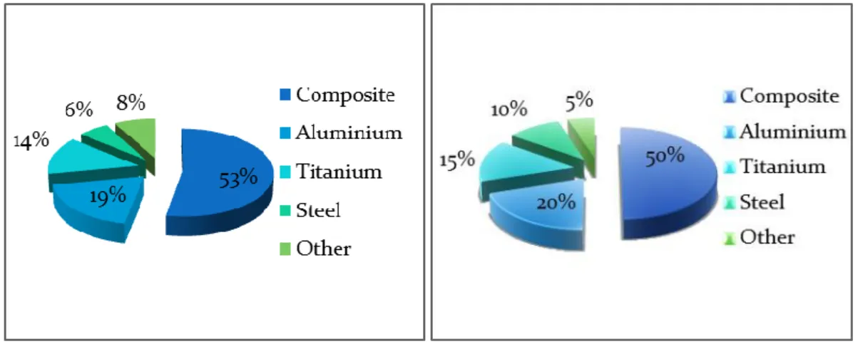
Fig 1. 1 Material Composition (a) A350 XWB (b) Boeing 787 ... 1
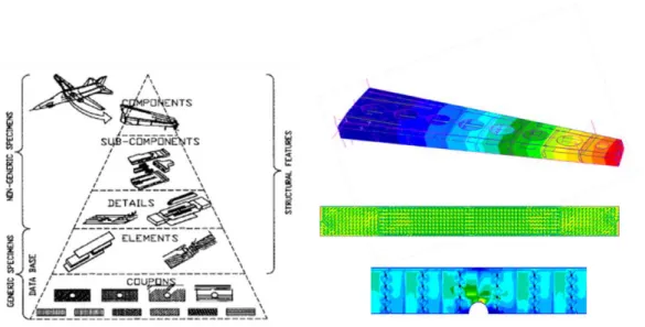
Fig 1. 2 Finite element analysis sequence (a)Theoritical (b) Followed... 2
Fig 2. 1 Laminate defination... 14
Fig 2. 2 Contact in between two bodies... 16
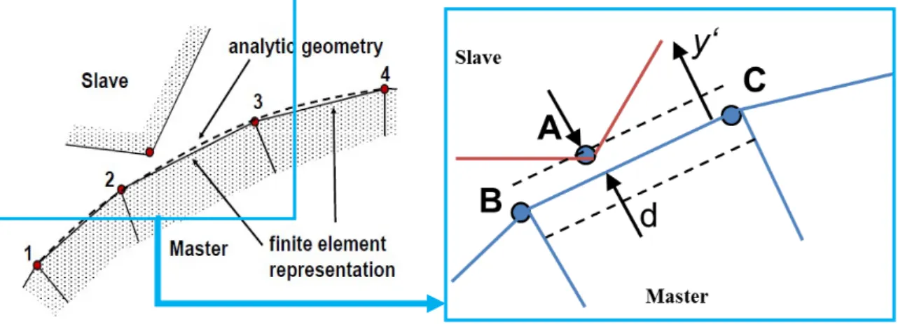
Fig 2. 3 Contact representations for finite element analysis and analytical analysis ... 17
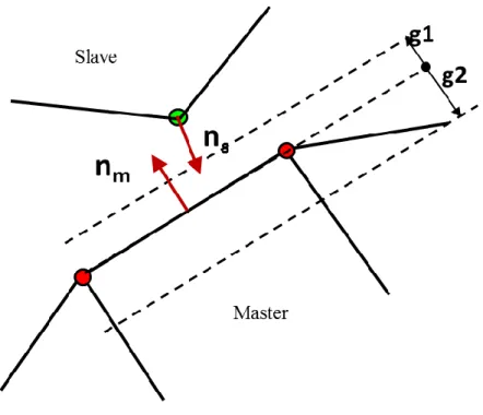
Fig 2. 4 Contact with gap definition ... 19
Fig 2. 5 Contact solution approach ... 19
Fig 2. 6 Stitching Process Performed by Troy Industries ... 21
Fig 2. 7 Cross-section view of stitched composites... 21
Fig 2. 8 Finite element modeling of stitch ... 22
Fig 2. 9 Contact definition between stitch and composite inplane ... 23
Fig 2. 10 Flowchart for contact solution... 24
Fig 2. 11 Contact detection between two bodies ... 25
Fig 2. 12 Detection of nearest node ... 25
Fig 2. 13 Iteration for loading and displacement distribution ... 26
Fig 2. 14 Plane ... 28
Fig 2. 15 Mode of composite failures ... 31
Fig 3. 1 Schematic of 6x6 stitched and 3x3 stitched laminates ... 36
Fig 3. 2 Experimental analysis of stitched laminates 6x6 Stitched and 3x3 stitched laminates ... 38
Fig 3. 3 Schematic of experimental analysis of stitched laminates ... 39
Fig 3. 4 Load and boundary condition of 6x6 Stitched and 3x3 stitched laminates 40 Fig 3. 5 Stitch modelling ... 42
Fig 3. 6 Stitch and composite modelling by contact ... 43
Fig 3. 7 Mode of failure identification ... 45
Fig 3. 8 Damage propagation of 6x6 detailed stitched laminate ... 48
Fig 3. 9 Damage propagation of 6x6 homogenized stitched laminate ... 48
Fig 3. 10 Damage propagation of 3x3 detailed stitched laminate ... 49
vi
Fig 3. 11 Damage propagation of 3x3 homogenized stitched laminate ... 49
Fig 3. 12 Digital image correlation ... 50
Fig 3. 13 Stiffness factor degradation of stitched laminates ... 51
Fig 3. 14 6x6 Stitched laminate failure with loadings ... 53
Fig 3. 15 3x3 Stitched laminate failure with loading ... 53
Fig 3. 16 Load-deflection distribution comparison of stitched laminates ... 54
Fig 3. 17 Stress-strain distribution validation of 6x6 stitched laminates ... 55
Fig 3. 18 Stress-strain distribution validation of 3x3 stitched laminates ... 55
Fig 3. 19 Stress-strain distribution comparison of stitched laminates ... 56
Fig 3. 20 Sub-section for transverse crack calculation ... 57
Fig 3. 21 Algorithm for transverse crack density quantization ... 58
Fig 3. 22 Transverse crack density ... 59
Fig 4. 1 Schematic of open-hole laminates (a) longitudinally stitched (b) transversely stitched ... 61
Fig 4. 2 Plain weave woven composite warp and weft tows arrangement ... 63
Fig 4. 3 Experimental setup of open-hole stitched laminates ... 64
Fig 4. 4 Schematic of plain weave woven composite laminates (i) warp and weft tows arrangement (ii) cross-section of unit cell (iii) micro-structures of unit cell (a) void/pure resin (b) undulated (c) straight cross ply ... 65
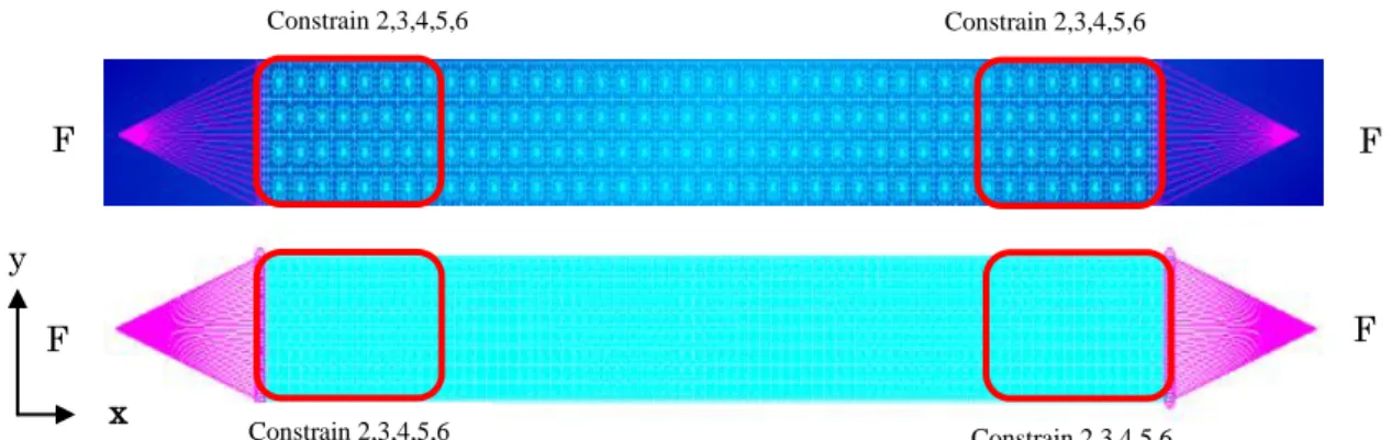
Fig 4. 5 Loading and boundary conditions for open-hole laminates ... 66
Fig 4. 6 Stitch modelling on open-hole laminates ... 68
Fig 4. 7 Stitch and composite modelling by contact ... 69
Fig 4. 8 X-ray radiography final damage (a) longitudinal damage (b) transverse damage ... 71
Fig 4. 9 Correlation with experimental and FEM of longitudinal stitched open-hole laminate ... 72
Fig 4. 10 Correlation with experimental and FEM of transverse stitched open-hole laminate ... 72
Fig 4. 11 Progressive damage analysis of stitched open-hole laminates second layer from top (a) longitudinal stitch (b) transverse stitch ... 74
Fig 4. 12 Stress-strain distributions of open-hole laminates with different stitch orientation (a) longitudinally stitched (b) transversely stitched ... 76
vii
Fig 4. 13 Stress history for open-hole laminates (a) longitudinally stitched
(b) transversely stitched ... 77
Fig 4. 14 Through thickness stress counters (a) longitudinal stitch (b) transverse stitch... 78
Fig 4. 15 Through thickness stress distribution at different points for open-hole laminates ... 78
Fig 4. 16 Stress concentration factor distribution for laminates ... 79
Fig 5. 1 (a) Advance Composite Wing (JAXA DESIGN) ... 83
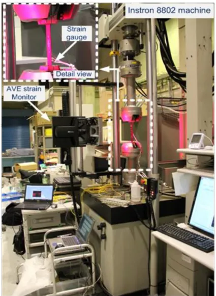
Fig 5. 2 . Experimental setup for advance composite wing structure ... 86
Fig 5. 3 Actuators with tension pad ... 86
Fig 5. 4 Stitched Composites spars ... 87
Fig 5. 5 Upper skin ... 88
Fig 5. 6 Lower skin ... 89
Fig 5. 7 Finite element model of wing structure ... 91
Fig 5. 8 Front spar connection with flange and splice ... 95
Fig 5. 9 Composite wing finite element meshing, loading, and boundary condition ... 102
Fig 5. 10 Front spar deformation ... 104
Fig 5. 11 Displacement sensor arrangement ... 105
Fig 5. 12 Front spar progressive displacement ... 106
Fig 5. 13 Front Spar (stitched and unstitched) deflection ... 107
Fig 5. 14 Progressive failure of stitched spar - tip ... 109
Fig 5. 15 Wing deflection ... 110
Fig 5. 16 Experimental Loading and response of composite ... 111
Fig 5. 17 Wing displacement isometric view from lower skin (b) Wing displacement upper isometric view from upper skin (c) Wing displacement in front spar and ribs ... 112
Fig 5. 18 DIC wing displacement counter at 20% ULT ... 112
Fig 5. 19 Contact status of components ... 114
viii
List of Tables
Table 3. 1 Material Properties T800SC-24k ... 41
Table 3. 2 Material Properties T800SC-24kf and Epoxy XNR ... 42
Table 4. 1 Material properties ... 67
Table 5. 1 Stacking Sequence ... 92
Table 5. 2 Laminate description of wing each component ... 93
Table 5. 3 Material Properties ... 94
Table 5. 4 Fiber and Matrix Properties of IM600-Q133 ... 94
Table 5. 5 Fiber and Matrix Properties of T800SC-24kf ... 94
Table 5. 6 Contact Patterns definitions ... 101
Table 5. 7 Experimental wing loads ... 103
Table 5. 8 Front spar deflection ... 108
ix
Nomenclature
x,y,z Global coordinate system of a laminate
x1,y2,z3 Coordinate system of a UD lamina, x1 is in fiber-parallel, x3 is in through thickness direction
E Elastic Modulus G Shear Modulus
v Poisson's ratio
Index denoting parallel to fiber orientation
┴ Index denoting perpendicular to fiber orientation SD Stitched Density
Sp Stitch pitch Ss Stitch space
ε Strain
σ Stress
γ Shear strain τ Shear stress
t Index denoting tension c Index denoting compression
f
m
Index denoting fibers Index denoting matrix
fr/fp Index denoting fracture / fracture plane
Index denoting fibre fracture / inter-fibre fracture
x
mσf p R RA
Magnification factor for matrix and transverse fiber stresses Inclination parameter
Strength of the material
Fracture resistance of the action plane δ
θ
Angle difference
Angle between an arbitrary action plane and the action plane
Xt Ply allowable stress or strain in the ply 1 direction for tension, usually in the fiber direction
Xc Ply allowable stress or strain in the ply 1 direction for compression, usually in the fiber direction
Yt Ply allowable stress or strain in the ply 2 direction for tension.
Yc Ply allowable stress or strain in the ply 2 direction for compression.
S Ply allowable stress or strain in the shear 12 direction.
1
Chapter 1
Introduction
1.1. Background
Composite materials are designed and developed by the combination of two or more macroscopic constituent materials to provide superior individual properties on a structural level. Light weight and high strength structure have been increasingly prevalent for aircraft and high-performance automobile. These high-performance composites structures exhibit both anisotropic strength and stiffness properties.
Carbon-fibre laminates failure is due to transverse crack, oblique crack leading to delamination. Through-thickness reinforcement (TTR) helps for the suppression of crack propagation. This increases the complexity of analysis and design of the composite structures.
Aircraft industries have focused on the excessive use of advanced composite materials on primary and secondary structures. Similarly, automobile industries have focused on
Fig 1. 1 Material Composition (a) A350 XWB (b) Boeing 787
2
composite monocoque structures. Taking account of aerospace industries, Airbus A350 XWB has shown its excellence of using 53% of the composite material of its total weight while next giant player in aerospace industry Boeing uses 50% of the composite material by weight. Fig. 1.1 shows the distribution of materials on recently designed and developed commercial aircraft.
The increases in the use of composites have significantly decreased the weight of the aircraft. This plays a vital role in the significant drop in fuel consumption for A350 XWB and Boeing 787 by 25% and 22% respectively. Moreover, corrosion resistance and improved durability can reduce airline operating cost due to a decrease in maintenance.
Aerospace grade composites are often carbon fibers set with epoxy matrix. Carbon fiber reinforcement plastics (CFRPs) are prone to delamination. TTR is in practice to reduce crack propagation. Braiding, Knitting, z-pinning, and stitching are used for 3D reinforcement. Stitching has been considered as one of the promising cost-effective methods to suppress crack propagation on CFRP.
Fig 1. 2 Finite element analysis sequence (a)Theoritical (b) Followed
3
For this study, a simplified macroscopic model has been developed. The effects of through-thickness reinforced stitched laminates were analyzed for laminate behavior under in-plane tensile loading. Interfaces between lamina and stitch yarns were assumed to be perfectly glued and modeled by the contact capability. To achieve this goal, step by step analysis has been carried out from coupon level (i.e. Open-hole stitched laminates, densely stitched laminates) to component level (i.e. Partial stitched composite stitch wing box structure).
1.2. Macro-Scale Modeling For Structural Analysis
3D structural modeling and finite element analysis have been carried out for stitched laminates because of their capability to achieve realistic physical representation and in-plane and out-of-plane laminate behavior analysis. A detail modeling approach with stitching has been incorporated because the idealized model has been reported to overestimate the strength1, 2.
Tanzawa, et al.3 performed 2D finite element analysis (FEA) for 3D-orthogonal interlocked fabric composite introducing slack absorption, tuning with frictional force.
This research gives the fracture phenomena of z-fiber yarn in which z-yarn was perfectly bonded initially. When axial force has been increased and it reaches designated limit load, z-yarn completely deboned from the in-plane layers. Soon after a crack has been developing, slack has been absorbed completely.
Puck‟s failure theory has been incorporated into the failure analysis. The maturity of this failure criterion for the prediction of lamina failures and post-failure analysis has been illustrated on World-Wide Failure Exercise- II (WWFE-II)4-6. On most of the aerospace grades, composite materials strain has been found to be large as compared to stress due
4
to matrix failure. Transverse crack is the most common crack arrested at initial phase loading on laminates which is followed by an oblique crack7. It has often been observed that delamination starts at that point where a macroscopic inter-fiber crack meets the interface between two laminates. This inter-fiber crack develops and allows delamination to different interfaces6. Nairn et al.8, 9 carried out a series of experiments on crack density as a function of applied load.
Woven fabric has gained attraction because of its lower manufacturing cost and stability at 0o and 90o to unidirectional laminates; it has a complex pattern due to its weft and waft tow interlaces10. Different numerical formulation, specific programming, and commercial finite element tools have been employed to solve microstructural problems.
Ishikawa and Chou11, 12 proposed a mosaic model, fiber undulation and a bridging 1D model for the study of the thermoelastic behavior of woven composites. The mosaic model was idealized as an assemblage of asymmetrical cross-ply laminates. Drawbacks of fiber undulation and fiber continuity in the mosaic model were addressed by the undulation model. The bridging model analyzed a satin weave woven composite. Naik et al.13 further developed the 2D model as an extended undulation model. Cox et al.14-16 formulated a binary model using two-node line elements and 8-node solid elements representing axial and transverse tows, respectively. Jiang WG17 proposed the domain superposition technique by independently meshing tows using solid elements. S.D.
Green10 modeled a 3D satin woven composite unit cell using the TexGen pre-processor following the voxel method and continuum damage model, which was hypothesized to represent the architecture more realistically. However, it has been considered impractical to model interpenetration at tow crossovers at the macroscopic structural level. Focusing on this difficulty, Tong et al.18 identified five different modeling
5
strategies.
1.2.1 Damage Characterization Of Stitched Laminates
Through-thickness reinforcement (TTR) helps to enhance interlaminar toughness and suppress damage in composite laminates. TTR is commonly performed by two methods.
The first method includes a reinforcement process performed on dry performs followed by resin infiltration and curing. This reinforcement process avoids severe fiber breakage than reinforcing in pre-preg tape19, 20. Earlier Kevlar thread was of greater interest on stitched laminates, while Kevlar demerits for moisture absorption resulting in-plane swelling was overcome by Vectran stitch21. The second method includes z-pinning reinforcement which is carried out before curing of the laminates18. A new approach for TTR was proposed recently by drilling the circular holes through-thickness and inserting fibrous carbon rods into the host laminates after it was cured. The bonding between rod and laminate was done by liquid resin22. Effective curing includes resin transfer moldings (RTM) or vacuum assisted RTM (VaRTM) because of their higher reliability and cost effectiveness as compared with autoclave curing23.
It has been widely accepted that there exists micro-damage on fiber-matrix composites during manufacturing24. The difference in thermal expansion coefficients of fiber, matrix and similarly between stitched and laminates residual stress are developed during matrix after curing6. With the increase in load, this stress gives rise to micro cracks which further develops to macro-cracks.
Research on stitched laminates indicates that strength, stiffness, and crack propagation depend on ply thickness, laminate streaking sequence, stitching thread properties, stitch row spacing and stitch pitch 25, 26. Cox27 reports that TTR is not strongly influenced by
6
volume content or diameter of reinforced stitch or 3D weaving tows. Moreover, it has been reported that there is a contradicting conclusion on in-plane properties improvement18, 28-33 or degradation25, 34 due to reinforcement. Findings that report reduction on mechanical properties on stitching tend to conclude that reduction is the result of fiber waviness or misalignment (In-plane and out-of-plane), breakage of in-plane fiber and resin-rich region. On the other hand, findings that report improvement of in-plane mechanical properties conclude that it is a result of effective suppression of delamination, and the increase of local fiber volume fraction because of compaction effect. However, it has been reported that stitching improves or degrades the tensile strength by less than 15–20% than unstitched laminates. Thus, a detailed study on the effect of stitch densities on composite structures to predict damage initiation and progression is expected to add value for designers seeking to enhance the quality of the structure.
1.2.2 Open-Hole Stitched Laminates
Notches and cut-outs on structures are inevitable due to various design requirements.
However, discontinuities in the structure are susceptible to damage initiation35, 36. TTR could be used to strengthen the structural properties. Dransfield37 and Mai38, 39 demonstrated that stitching offers considerable promise as a low-cost method for TTR to strengthen in-plane mechanical properties. Cox27 reported that TTR is not strongly influenced by the volume content or diameter of the reinforced stitch or 3D weaving tows. Mouritz‟s review on GFRP40 and FRP41 (limited to woven, knitted and braided composites) noted that there are contradictory reports on whether in-plane properties improve or degrade upon stitching.
7
Few reports have been found for single stitch but they do not specify prediction of failure and structural strength. X.P Han et al.42 carried out an experimental investigation on non-woven composite laminates with a circular single and double stitching reinforcement around the central hole. These studies agreed with the conclusion that reinforcement enhances tensile strength. Yudhanto A, et al.43 experimentally investigation states that densely stitching improves tensile strength by 10.4%.
At an early stage, Whitney and Nuismer formulated failure criteria for open-hole composite laminates44. Since then, numerous experimental and numerical investigations have been carried out for characterization and prediction of the notch strength of open-hole laminates1, 45-48. Despite extensive studies on open-hole laminates, studies on the effect of the stitch on open-hole stitched laminates are limited. This and Bron49 studied notched strength for different stitching densities and found a reduction of 54%
tensile strength at a density of 10/cm2. Mouritz et al.50 and Zhang et al.51 investigated Kevlar-stitched laminates and reported that stitch orientation does not affect tensile strength. X.P Han et al.42 carried out an experimental investigation on non-woven composite laminates with a circular single and double stitching reinforcement around the central hole. K. Gliesche52 performed an optical investigation on the open-holed tailored fiber placement process (TFP), implemented to reinforce non-woven composite laminates with a grating method from GOM Corp, and Yudhanto A et al.43 experimentally investigated longitudinal and transverse parallel stitched open-hole plain weave woven laminates. These studies agreed with the conclusion that tensile strength is improved by reinforcement.
8
1.2.3 Composite Wing Structure
Composite materials are being used to reduce weight with improved strength. Research has shown that aircraft designed with carbon-fiber composite laminates can achieve weight savings of 20% to 30% over similarly designed metal structures. Composite properties of better fatigue resistance, corrosion resistance with flexibility for complex shapes has increased its application in numerous industries. Boeing in 1950‟s started its journey of composite by 1% of structure on Boeing 747 which significantly increased to 50% till it moved to manufactured Dreamliner 787 while next competitive aircraft manufacturer, Airbus took its journey of composite by 5% of structure in 1980‟s on A310-300 to 53% till it manufactured A350 XWB in 2014 for reduction of air travel cost.
Holt and Cacho-Negrete assessed stitching of composites for joining uncured carbon fiber-epoxy prepreg laminates to obtain high strength lap joint. NASA Advance Composite Technology (ACT) researchers in 1980s looked as a breakthrough technology for through-thickness stitching of textile composite to provide reinforcement for damage tolerance using primitive single-needle stitching machine, reassembling a scale-up version of the household sewing machine. Since then a number of research has been performed globally for stitched composite involving the development of Advanced Stitching Machine (ASM) and the invention of various apparatus for production of a three-dimensional (3D) fabric which is capable of manufacturing small specimens to large airframe substructures.
Through-the-thickness stitching of dry preforms, combined with resin infusion, showed a good potential for overcoming cost and damage tolerance issues. Stitching through dry
9
fabric made it possible to incorporate various elements of a wing torque box (i.e., wing skin, stiffeners, intercostal clips, and spat caps) into an integral structure that eliminates the requirement for thousands of mechanical fasteners. Replacing mechanical fasteners with a highly automated stitching process has the potential of significantly reducing manufacturing costs of composite structures. However, uses of composite materials on aircraft structures are still limited. Composite materials are not isotropic and its complexity in damage initiation and damage propagation needs in depth knowledge of composite structures.
1.3. Problem Statements and Objectives
A detailed study on the effect of stitch parameter, i.e. stitch density, on the damage initiation and quantification is required for an understanding of damage mechanisms.
This study helps to understand the behavior of laminates on a structural level to determine appropriate reinforcement density and the reinforcement location. There are numerous studies carried out for carbon-fibre laminates but very few studies are done on a single stitch. Moreover, TTR composites structure exhibit complex through-thickness stress distributions that result in increasingly complex structural models. Thus, step by step is essential from coupon to structural level analysis.
Japan Aerospace Exploration Agency (JAXA) has designed and developed advanced composite wing. The experimental specimen has a unique design of 5000 mm length, in which stitch composite has been used on the front spar with 2000 mm. The theme of this thesis is to perform numerical analysis of the partial advance composite wing for displacement and strength analysis under static condition. Failure analysis of composite structure has been a great interest. Furthermore, the objectives of this thesis are
10
highlighted below:
• To develop and analyze a simplified macroscopic structural model for the stitched laminate coupon test and utilize this method for the analysis of partial advance stitched composite wing structure. This modeling technique is to be capable for predicting and damage characterization of coupon test laminates to aircraft primary aero-structure.
• To develop a detail model that is capable enough to capture the effect of each stitch on laminate at macroscopic level, which was difficult to characterize during homogeneous analysis method and experimental analysis.
• To develop detail macroscopic model that is capable of performing progressive failure analyses to characterize the failure behavior of the laminates and advance stitched carbon fiber/epoxy composite structures.
1.4. Overview of the Thesis
Aircraft flight performance greatly depends upon aerodynamics and it's airframe structural weight; which directly impacts fuel consumption and aircraft maneuver. The most used composite materials in primary structures of an aircraft are carbon-fibre/epoxy composites in the form of laminates. Japan Aerospace Exploration Agency (JAXA) has designed and developed advanced composite wing.
The objective of this thesis is to perform numerical analysis of the partial advance composite wing for displacement and strength analysis under static condition. To
11
achieve this goal, step by step analysis has been carried out from coupon level (i.e.
stitched laminates, open-hole stitched laminates) to component level (i.e. Composite wing box structure). Progressive failure analysis to study the effect of stitch with different densities and orientation has also been a great interest.
Introduction to stitched composite, as well as literature review and objectives of the thesis, are presented in Chapter 1. Through-thickness reinforcement (TTR) helps to enhance interlaminar toughness and suppress damage on composite laminates. Few reports have been found for a single stitch. A detailed study of stitch laminates on the damage initiation and quantification is required for an understanding of damage mechanisms which will add value to the designer to improve the quality of stitched composites structures.
Chapter 2 presents the formulation for laminates. Numerical analysis has been carried out to study the effect of through-thickness reinforcement based on stitching density and stitching location. The macroscopic structural model has been developed for this study.
Moreover, lamina and stitch are discretized and the interfaces between them are modeled with contact capability. Puck failure criteria and analytical stress concentration formulation for discontinuous structure has been described on this chapter.
Progressive failure analysis of carbon-fibre/epoxy composites laminates with varied densities has been described in chapter 3. Detailed macroscopic multi-layered stitched laminates were modeled on the lamina-wise basis, to obtain the macroscopic damage and the local stress-strain constitutive behavior. It is to be noted that idealized model overestimates the results. Hence, detail modeling is essential to study the effect of stitching for effective prediction and analysis. This analysis showed reinforcement
12
density is one of the key factors that affect the strength, the stiffness and the crack propagation on composite laminates.
Numerical analysis of different stitches oriented in the longitudinal and transverse directions around the hole has been described in chapter 4. It has been noted that research on "open-hole laminates” is concentrated on notch sensitivity depending on the ply thickness, the hole-size and the geometry of the laminate stacking sequence. And research on "stitched laminates" indicates that strength, stiffness, and crack propagation depend upon the ply thickness, the laminate stacking sequence, stitching thread properties. In both the research areas i.e. open-hole and stitch laminates, the effect of stitch orientation is still under investigation and is of greater interest. During these modeling simplified modeling technique had been developed.
Numerical analysis of stitched composite of partial advance composite wing structures has been described in chapter 5. Stitched composite structural analysis has been validated with experimental results for partial composite wing structure. This FE modeling technique has been successful in capturing the deflection behavior of stitched spar tip and unstitched spar root, joined together to form front spar. Progressive failure analysis of stitched composite front spar tip has been able to characterize the damage mechanism.
This analysis shows that stitched composite can be used for primary structures in an aircraft. Implementations of stitched laminates on wing structure give robust shape with the improved aspect ratio. Thus, this analysis shows that use of stitch composites on aero structure has structural and aerodynamic improvement.
Finally, a summary of the thesis has been presented in chapter 6. Numerical analyses of various stitched laminates are performed effectively and accurately in macroscopic structural level. This detailed modeling technique helps to understand the effect of stitch
13
density and stitch orientation on composite structures. Moreover, this technique of numerical analysis has been capable enough to predict the displacement and stiffness of the advanced stitched composite wing structure. This type of detailed analysis of stitch laminates can be valuable for designers seeking to enhance the quality of the structure.
14
Chapter 2
Finite Element Formulation
2.1. Finite Element Formulation For Lamina And Stitch 2.1.1 Continuum Mechanics at Lamina
On the lamina level, the fiber-matrix composite is regarded as a homogeneous but anisotropic material. Laminas in laminates on composites are designed as per the applications. Lamina are named as per the fiber direction as shown in fig. 2.1. They are ranged from positive 90 degree to negative 90 degrees.
The direction parallel to fiber is indexed as ∥ and direction perpendicular to fiber is indexed as ⊥. On the lamina level, the stress analysis assigns a state of stress to any state of strain or vice versa, i.e. this is the level where the constitutive behavior of the individual lamina is interpreted. The constitutive behavior, which relates states of stress to states of strain, is then defined by the compliance matrix given by:
0o lamina 90o lamina
Fig 2. 1 Laminate definition
15
(2.1)
2.1.2 Continuum Mechanics Formulation For Contact
Numerical analysis is based on the principle of virtual work where body undergoes large displacements and large strains with the non-linear stress-strain relationship. For the analysis of solids and structures, a Lagrangian formulation usually represents a more natural and effective analysis approach. The finite element solution of governing continuum mechanics equation is obtained by using discretization procedures for the principle of virtual work and in addition to contact traction through externally applied forces and the constraint equation defined as53.
(2.2)
Where,
= Cartesian component of the Cauchy stress tensor
1 2 3 12 13 23
1/ / / 0 0 0
/ 1/ / 0 0 0
/ / 1/ 0 0 0
0 0
E v E v E
v E E v E
v E v E E
1 2 3 12 13 23
0 1/G 0 0 =
0 0 0 0 1/G 0 0 0 0 0 0 1/G
t t
i j 1
1
1
t t t t
t t
t t
t t t t t t t t
t t t t
f i
t t t t
t t
c i
N t t t
ij ij
L V
N B S S
i i i
V S
L
N c c
S i L
e d V R
u f d V u f d S
u f d S
16
= Strain tensor corresponding to virtual displacement
ui
=Virtual displacement vector imposed att t, a function of ttx jj, 1,2,3
t t
xj
= Cartesian coordinates of material point at t t tt
V
=Volume at time t tThe component of contact tractions are denoted as ttfic which act over are ttSc
and components of externally applied tractions are denoted as ttfiS , and act over the area ttSf . We might assume that ttSf is a part of ttSc although such assumption is not necessary.
Now, if we consider two bodies I and J with each body supported such that without contact no rigid body motion is possible.
(a) (b) 1
2
i j
t t ij t t t t
j i
u u
e x x
t t f IJ
Body I t tscof body I
t t f J I
Body J
o f b o d y J
t t
sc
Fig 2. 2 Contact in between two bodies
17
Contacts are primarily used to join 2 dissimilar meshes. The above fig 2.3 can be represented for two bodies during the analysis. Master and slave bodies are in contact together in finite element analysis. The finite element representation of composite are represented by master body and slave node is a representative of stitched. These finite element representations are further simplified to analytical geometry with segment and node on the fig 2.3.
Contact must initially be true. MPC equations are used as contact constraints in this case (for general contact Lagrange Multipliers are used). When edges or grids are to be glued, glueing can also be done for the rotational DOFs (Moment Glueing). A deformable body is a collection of finite elements.
Then virtual work due to contact traction from equation 2.2 is given as:
(2.3) Let, tfiIJbe a vector of contact surface traction on the body I due to contact with body J, then tfiIJ =tfiIJ. Also, i
uI
and
i
uJ
are the components of the virtual displacements
IJ i JI i IJ i
I IJ IJ J JI JI IJ IJ IJ
i i i
S
u f dS
S u f dS
S u f dS
Fig 2. 3 Contact representations for finite element analysis and analytical analysis
18
on the contact surface of the body I and J respectively. SIJ and SJI contact pair, not necessarily of equal size. Now we can decompose corresponding contact traction
t IJ
fi acting on SIJ into normal and tangent components n and s on SJI as.
(2.4) Where, and t are the normal and tangent traction components. Thus
tfIJ Tn t;
tfIJ Ts (2.5)
To define the actual value of n,s that we use in our contact calculation, consider a generic point x on SIJ and let y*(x,t) be the point on SJI satisfying
(2.6) The (signed) distance from x to SIJ is then given by gap function g
. *
T *g x t x y n (2.7) Where, n* corresponding to point x is unit normal vector at y*(x,t). Thus condition of normal contact definition as:
0; 0; 0
g g
. (2.8)If g>0 then we must have =0 and vice versa.
The following fig 2.4 represents the gap in between the segment and nodes. Contact tolerance is measured normal to the master contact body as shown below. `n` is the contact normal. The slave node should be in the range of the gap which would result in the convergence of the numerical solution. If a contact tolerance is too small, detection of contact is difficult, leading to higher costs. This result in initial contact might not be found If contact tolerance too large, nodes are considered in contact prematurely,
tfIJ
n+ st
2 2
* ( , ) minJI
x y x t y s x y
19
resulting in a loss of accuracy. Nodes might “penetrate” the surface by a large amount.
During finite element calculation, if there are gaps and overlaps within the contact tolerance zone between a contact body pair, a slave node is considered in touch with the master surface. It has been represented by fig 2.5 below.
Fig 2. 4 Contact with gap definition
Fig 2. 5 Contact solution approach
20
To include frictional condition, Coulomb‟s law of friction holds pointwise on the contact surface and thatis the coefficient of friction. Letbe non-dimensional variable given by t , where
are the frictional resistance and the magnitude of relative tangential velocity given by(2.9) Corresponding to the unit tangential vectorsat y* ( , )x t .Hence u x t s( , ) *
is the tangential velocity at the time t of the material point at y* relative to the material at x. With this coulomb‟s law of friction states
(2.10)
Now, let w be a function of g andsuch that w(g,)=0 satisfy eq.(2.9) and similarly v be a function of uand such that v=0 satisfy Eq.(2.11) The variable and be considered as Lagrange multipliers so and be variations in these quantities. Thus, by multiplying and integrating over SIJ we obtain the constrain equation.
(2.11)
2.2. Contact Modeling
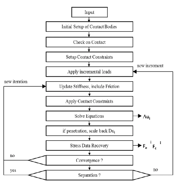
Finite element contact simulation has been based on the flowchart presented on fig 2.10. The contact solution models the sliding of finite amplitude between deforming bodies. This formulation can model nonlinear contact with large- deformation between the deforming bodies can have large deformation. MSC Nastran user defined
1
1 implies 0
1 implies sign( ) =sign( ) u
u
, , 0IJ
IJ S w g v u dS
*( , ) ( , )
( , ) ( j|y x t j|x t ) *
u x t u u s
21
subroutine has been used for the definition of contact between stitch and composites on coupon analysis and assembling of parts during structural modeling of wing structure.
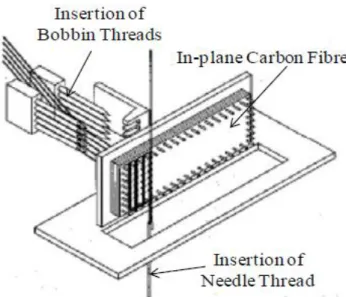
For the modeling of stitches, the emphasis has been placed on properly characterizing the stitching process. The stitching process consists of inserting a needle and carrying a stitch thread through a stack of fabric layers as in fig 2.6. Fibers are arranged along two axial lines, and a series of stitch yarn with predefined pitch are thrust into the fiber layers19. Fig 2.7 is the x-ray radiography image of stitched laminates showing stitch cross section.
Fig 2. 7 Cross-section view of stitched composites Fig 2. 6 Stitching Process Performed by Troy Industries
22
During the stitch modeling it has been idealized. Stitch fiber on z-direction has been modeled. Stitch knot and bobbin thread has been ignored for the computational ease. Fig 2.8 illustrates the finite element modeling of the stitch thread on stitched laminates.
The finite element formulation for separation and sliding on contact of finite amplitude between three dimensional deforming bodies are based on penalty method. Fig 2.9 defines the contact between the stitch nodes and composite elements. Stitch elements have finer mesh than the composite mesh. These stitch outer element nodes are in contact with the composite element surface. During subroutine definition stitch nodes are defined as slave and composite nodes as master elements. The gap between these nodes and surface are assumed to be 0.5 mm. Subroutine for stitched laminates are highlighted as below.
Bobbin Thread Stitch Knot
Needle Thread
x z y
Stitching
Fig 2. 8 Finite element modeling of stitch
23
Contact Nodes Stitch
Elements
Composite Elements
Fig 2. 9 Contact definition between stitch and composite inplane
24
The above flowchart explains the contact simulations. Once deformable-deformable bodies have been selected, contact is to be defined. Then contact detection between two bodies is checked. Flowchart in fig 2.11 shows the contact detection for stitch nodes and composite in-plane segments. Contact status is important for the finite element solution for smooth loading of the system. Flowchart below defines the contact in-between the master segments and the slave nodes. Every node is checked for the contact to the nearest segment defined by gap function. The slave nodes has identified
Fig 2. 10 Flowchart for contact solution
25
and associated to the nearest master segment as an example shown in fig 2.12.
Fig 2. 11 Contact detection between two bodies
Fig 2. 12 Detection of nearest node
26
When there is contact between node and the segment of the body contact setup has been applied with material properties and contact properties. The gap tolerance has been defined. Then loading has been implemented in-between the bodies which would be transferred on contact. Only at the start of an increment slave is considered for contact. Apply contact constraint and iterate until the solution converges. Then check the contact force. In case of separation continue iterating. Otherwise go to the next increment. During the analysis the iteration technique is required as the contact equations goes non-linear.
Fig 2. 13 Iteration for loading and displacement distribution
27
2.3. Failure criteria
Puck‟s theory has evolved from extensive experimental studies of the mechanisms by which failure occurs in a lamina when subjected to a biaxial stress state. Puck‟s theory contains a very sophisticated treatment of inter-fibre failure, through the introduction of the several competing ply cracking mechanisms and consideration of the orientation (angle) of the fracture plane.
The Puck theoretical failure envelopes for the unidirectional laminae were in very good agreement with the experimental results. The predicted final failure envelopes and stress–strain curves for the multidirectional laminates were also generally in good agreement with the measured ones. Puck‟s theory6 has been the most promising approach for 3D application.
The maturity of this failure criterion for the prediction of lamina failures and post-failure analysis has been illustrated on WWFE-II )54,55,5,4. It defines two types of failure: the fiber failure fE FF, and inter-fiber failure fE IFF, is basically known as matrix cracking.
However, post-failure analysis can address delamination6. While, in this analysis delamination, has not been considered. This failure criterion is physically based on Mohr-Coulomb hypothesis and mathematical formulations appropriate for brittle fracture.
The failure is caused by normal and shear stresses (σ τn, n1 and τnt) acting on the fracture plane inclined of θfp to the material plane as illustrated in fig. 2.14. x1,x2,x3 denotes coordinates system of lamina in fiber-parallel, transverse and in through-thickness direction while in and it is coordinated system of action plane normal to fiber normal and fiber-tangential.
28
The applied stresses 1, , ,2 3 23, 21, 31 (referring to the UD-lamina system) which have to be transmitted by the matrix and the fiber/matrix interface. ij , are shear stresses with first index “i” representing normal to action plane and second index “j” representing the direction of shear stress. andindicates a cylindrical coordinate system of lamina being parallel to fiber and perpendicular to the fiber direction. P R R, , Aare inclination parameter, the strength of the material and fracture resistance of the action plane.
/ ,f / , /
c t m fr fpare index denoting compression/ tension, fibers/ matrix, fracture/fracture plane respectively. is the angle between an arbitrary action plane and the action plane of 2.
Following expression6 defines fiber failure fE FF, under a combined load:
, , 1 2 3
1
for a 0 for a 0
E FF t c f
f a t
t
f E
R E
R R
(2.12)
Stress magnification factor mf has been introduced, which is suggested to be 1.1 and 1.3 for glass fiber and carbon fiber composite respectively. [Puck 1996; Fischer 2003; Puck
Fig 2. 14 Plane