LasDc9Ei-
.fo':,.lil..,, ,.,,.',,,.
,.',
,.,.
.,,'
{OT",:".a,i..O,fi
.S.`g".Cf`"A'r})""Nd.
fi3os"6?tro':i;R;n.,E.
n,g,i,n,eerin.g
gpt,e,
,asl#ivax$,?yijva,tiT::1
t
tt
tt
ttt
t
/ttl
.tt
t
t
t
EXPERIMENTAL
STUDY
ON
INTERNAL
CRACKING
'
'
OFPARTIALLYPRESTRESSEDCONCRETE/
・
'
tt
tt tt t/
FLEXURAL
MEMBERS
'
・
c....
Part
1
:
Examination
of
double
injection
technique
by
KAZUO
SUZUKI*,
YOSHITERU
OHNO**
and
SOMCHAI
SRISOMPONG"'*,
Members
of
A.
!.
J,
1.
Introduction
Degree
of
corrosion
of
reinforcing steelsin
concrete structures mustbe
relatedto
the
severity of cracking'and
loss
tt
.
t
of
the
composite
action
between
reinfercing steels and concrete orthe
separation of concretefrom
reinforcing steelsdue
to
the
large
difference
'in
their
strain
capacities[
1
].
Not
only surface crack widthsbut
'aiso
the
internal
cracking characteristicsare,
thought
to
be
impprtant
for
the
corrosion controLThese
factors
also relateto
the
bond
mechanismbetween
reinfercingsteels
and concrete.Until
today,
some studies oninternal
cracking
of reinforced concrete(RC)
prisms
withdeformed
bars
have
been
'
tt
t/t
tt
tt
reported,
In
ordinaryprestrqssed
conciete(PC)
structures, crack controlis
not requiredbecause
cracks are not allowed.Therefore,
cracks
in
the
vicinity of sheath andin
grout
have
scarcelybeen
investigated.
But
atthe
present
time,
the
newlydeveloped
partially
prestressed
concrete
(PPC)
structures arebecoming
extensively used.In
these
structures, cracks are allowed under
service
Ioad
but
the
available experimentaldata
foT
areasonable crack control are-still verylimited.
The
study
in
this
field
is
in,urgent
need,・・
・
'
In
this
paper,
the
investigation
techniques
which employink
andlor epoxy resin asinjecing
materials'arediscussed.
An
idea.was
conceived
that
in
orde[
to
investigate.internal
cracking moreprecisely
andto
obtain not onlygeneral
crackingpattern
but
also
sizes
ofc[acks
directly,
ink
and resin couldbe
usedtogether
in
the
same specirnen.The
technique
is
termed
herein
"doubleinjection
technique".
In
this
paper
the
examination ondouble
,injection
technique
is
mainlydiscussed
andthe
internal
cracking characteTistics willbe
discussed
in
Part2.
2.
Historical
Background
In
1965
Broms
[
2
].introduced
atest
technique
for
investigating
internal
crackingby
means of resininjection・in
reinforqed concreteprism
for
which a small resininjecting
hole
wasprovidecl
in
parallel
wjththe
deformed
reinforcing
bar.
The
specimenwas
externally
coatedto
prevent
outside airfrom
enteringinto
it.
Loading
wasdofie
by
pulling
both
protruding
ends ofthe
bar.
Vacuum
pump
was applied,to removepart
ofthe
airtrapped
inside
the
specimen which rnightprevent
resinfrom
penetrating
into
the
veryfine
cracks.With
the
co.rnbination of airpressure
and vacuum usingtwe
pumps,
resin wasdrawn
into
the
e{4cks.The
injecting
pr,efisure
wasapproxiTn.ately
7.Q
kgflcmZ
for
whichBrorns
gave
a commentlater
that
it
was ratheThigh
because
the
axialforce
resultedfrom
this
pressure
might cause some ofthe
intemal
cracksto
open up.The
load
was maintainedtill
the
hardening
of resin.The
specimen was cut
to
reyealinternal
cracks whichhad
been
preserved
by
the
hardened
resin.Width
ofprimary
crack adjacentto
the
reinforcing steel wasfound
to
be
only115
to
113
ofthe
maximum width at concrete surface.The
minimum crack width measuredin
the
test
wasO.
025
mm.Since
ink
injection
was notperformed,
otherdetails
ofinternat
cracking,for
instance,
pattern
ofinternal
cracks and separation of concretefrom
reinforcing steels were notinvestigated.
'
PTofessor
ofOsaka
University,
Dr.
Eng.
#
Research
Associate
ofOsaka
University
i"
Graduate
Student
ofOsaka
University
Manuscript
received Septernber7,19S4
-24-NII-Electronic Library Service
In
the
sarneyear,
Goto
[
3
]
reported someinvestigations
ofinternal
cracks whichoriginated
from
lugs
ofdeformed
bars,
based
on
the
test
using reinforcedconcrete
prisms.
Ink
wasfirst
filled
into
the
injecting
holes
placed
in
parallel
with
the
reinforcingbar.
L,oad
was appli6dby
pulling
both
protruding
ends ofthe
bar.
As
cracksopened,
ink
was automatically
drawn
into
them
by
the
aid ofinternal
vacuum suction.In.1971
the
optimum results,illustrations
and schematicdiagram
ofthe
internal
crackspattern
tested
by
this
procedure
[4']
wereintroduced.
Goto
et al[s]
also studied shapes ofprimary
cracks
by
injectin'g
resininto
reinforced concreteprisms.
They
statedthat
when
deformed
bars
were usedthe
interior
opening ofpJimary
crack was net regular.Furthermore,
crack widthsadjacent
to
the
steel surfqce was much smallerthan
those
observed atthe
concrete surface.Goto
did
not
state
the
relationships
between
the
pattern
ofinternal
cracks ancl sizes ofpTimary
cracks
in
the
sarne specimen.In
]972
IIIston
&
Stevens
[1
]
fOllowed
Broms'
technique
andperformed
test
oninternal
crackingin
reinforcedconcrete
beams,
Internal
shapes ofprimary
cracks wereobserved
to
be
irregular,
forked
anddiscontinu6us.
Separation
of concTete'from
reinfovcing steel was also observed,but
the
separation clearanceancl
its
areain
relation with crack width or steelstress
were notdiscussed.
The
minimum width of crack whidh resin couldpenetrate
was approximatelyO.Ol
mm,
Since
ink
injection
was notperformed,
the
formation
ofinternal
crackswas unobservable.
・
Previous
works oninternal
cracking mostlydealt
with reinfoTced concreteprisms.
Those
onbeams
are still rare.Particularly,
investigatiops
on
intemal
cracking ofpartially
prestressed
concretebeams
have
notbeen
clealt
with,i,
e,there
is
none
of
experimental
data
of crackingin
the
vicinity of sheath'andin
grout.
Those
previous
works employed eitherink
or resininjections
which wereindependently
performed
to
obtain either crackingpattern
or crack widths only.In
ordeTto
investigate
directly
not onlygeneral
cTackingpattern
but
also sizes ofthe
cracks asthey
arein
the
same specimen,those
conventional
injection
techniques-are
consideredto
be
impractical.
3.
PreliminaryTest(Exp.1)
3.1
TestProgram
Specimens
and materialsObjective
ofthe
test
is
to
acquire abetter
injection
test
teehnique
usingink
and epoxy resin as'injecting materials,Ink
dyes
cracks and allows observationfor
internal
crackingpattern,
whereas epoxy resin retains crack openings and allows measurement of craek widths.Eight
beams
with10
×・20
cm rectangularTable
1
Beam
specifications(Exp.
1)
tion
andthe
-length
of150
crn of reinforced or・
partially
prestressed'concrete
werefabricated
and arranged
in
'four
pairs,
and eachpair
sisted of
beams
ofthe
samedescriptions.
One
of each
pair
wasto
be
injected
withink
and
the
'
"9.
,29,.
.,
r
,J.,''
- RC:Retnferced conerete, 2o,
io-c. prc<Table2
Properties
of concrete andgrout
'
rc'M PPC-MFig.1
Sectionat
detai]s・of
test ,beams
ofExp.1
(in
cm) ,Beammark-InjectedvithConcretetypePre-stressing
steelPrestressingforce(kgf)
RC.CInkConcrete
'
-'
RC-CResinConerete
.
,.
RC-MInkMortar
-t
-RC-MResinMortar
.L-
-ppc-cInkConerete"11bar
8000
ppc-cResinConerete11bar
8000
PPC-MInkMortar
¢11bar
8000
PPC-MResinMerter
¢ltber
sooo
Item
Cenclete-type
Ageattest(deys)Compressive
c:$:::sljModulusef
elesticlty(kgf!em`)Tensile,{};::gs?
Concrete
20
387
2.82xlo538・.2
E)cp.1Morter
22'
354
2.40xloS
./t
Grout
14203
-
27.9
Exp.2Concrete41
331
2.71xlo531.4
'
X3LrFig,2
Eifl},t/S,li
--Li3i
Detalls
ef reinforcing steeLtin
mm)-25
--other with
resin.
Details
ofthese
beams
areishownin
Table
,1and
Eig:1.
Concrete
wasprepared,,in,two
types,
one,was'
of
・crushed
stone with a'maximum size of10:mm,
the
other・,
wasof/
saDd-cement mortar./・High:e,arly-str.engthportland
ce-lment
and
riy,er sand were used.Waterlcement
ratio wasO.55,.
For
grb'u'
t,
Pozzlith,No.8
of
O,zs
%
and aluminumpowder,
ofO,
Q05
%
ofthe
cementby
weight were mixed with cementpaste
with waterfcement ratioof
O.45.
Th'e
propT
,i
erties
of
concrete
andgrout
at, ages oftest
a;e shownin
Table2.
''
''・
'./・//
'・'
'''
i'''''
,
Reinforcing
steelbf
D
1・9
was-usedfor
alltest
bearns.
The
details
of
this
steel are shown.inFig.2
The
prestressing
,
steel wase11
mmsmooth
type
bar
placed
in
a spiral・sheathof
23
mminner'diameter;
Injecting
holes・were
provided
by
inlaying
¢
3
rnm steel wiresin
the
cleaTance of6-7mm
be-tw.een
reinfercing steel andthe
outer surface of sheathin
pa-railel
,with
them.
One
day
after concrete casting-the,steel
wires
werepulled
ollt,
One
injecting
hole,for
investigating
gracks,in・,,grout
wasprovided
inside
the
sheathin・parallel
withthe
prestressing
sleel,
The
diagram・of
construction,is shownin
Fig`3.
The
specimens,were
kept
moistby
means
of ,wet
cloth
andplastic
sheettill
loading
test
Forms
werere-moved after
2
dayg
to
allow
contacttype
straingauges
to
be
attachedfor
measuringstrain
changesin
the
concrete.Prestress
crete
beams
atthe
age of7
days.
'
Shrinkage
of concrete,was observed・since removal・ offorms
till
only
loss
ofprestressing・force
in
the
prestresSing
steelbut・'also
reinforcing steelinto
account..Loading
and
injecti'ng
method・.
,.
'
Arrangement
for
loading
was aicantil'evertyPe.
Each
beam
end,as
slibwnin
Fig,4,
The・,color
Dfink
wasred,
and red'
error resuLts-ofthe
preparatofy,,teSts,・
injecting
pressure
oftespectively.
Before
loadirig
ink・or
resin wasfilled
into
the
'
loaded
while
the
press,ure
was,maintained.As
cracksformed
the
cracks
by
injecting
pressure
from
outside andthe
aidof
Change
in
stgel stressfrom
the
decompression
Aab
wfts'
cantilever.
・
,
'
For
mk-injectedlbeams,
l,oad
was removed afterholdin
was maintained
fef
about
one weekfor
resinhardening.
After
the
plane
whichpassed'
through
the
reinforcing steel orboth
longitudinally
cutinto
two
,parts.
Then
yisualinspec.tion
.
t
'
t
/
mlcroscope:
,/'・
'
,
,,,
'
During
the
test,
changes
is
surface crack widths werec/
gauge
length
onthe.coricrete
surfaceat
the
level
of rein wasdone
in
yaf'i6us stages,i.
e,before
loading',
after''/
Z:i:'X//:,gb,,,fi.;2ge,tlr`.e,L",a,i,.c,reck`,"g
can notbe
dt.I7f,tiy
,
3.
2
ResuLts
ofInjection
andConsiclerations
'
-26-ii
・・
'
1..r'・r
!i
i'
':
$:
Injeqt injeetinijt ttt/Fig.
3.・:
Fabrication
details/
bartote '
tt
.
boadcell'tt'
Centactgagepaintgf
.Oil 'tetttttttttttttttttttt
ttttttttttttttttttt
Spec ±men F・" Fixedendttt H-steElbearn 30 llOesn le[ was
plgment
wasO.5
mjecbng
the
internal
controllgcl
g
fQr
afew
unloading,'
{einforcing
was.t/
measureforcing
.and
prestressing
steels ln]ectlonchecked,
//t/'
'/.
jaek
rnk.er tesinFig.
4
Loading
&,
a[rangemgnt ofin]ection
<E,xp.
1)
was
transferred
to
the
partially.
prestressed
t tt
tt
loading
ancl
injection
test,
in
orderto
take'not
the
increment
of compressionforce
in
the
/
/
t
/t
tt
loiaded
at apoint.
11o
cmqpart
from
the
fixed
added
into
the
resin,Basied
ontrial
andand.5.okgflcm2
were usegfor
ink
andresin,
'
i,
holes
as shownin,Fig.3.
Beagis
werethen
filled
ink
oT [esin}vas
immediately-drawn
into
vacuum suctioh autgrnatically
produced.
at
3200kgflcm2at
the
fited
end
ofthe
'
minutes.
For
resin-i,njected ones,cleflection
beams
were vertically splittedthrough
,
a.ndprestressing
steels..The
grout
wasdond
withthe
aid of a2o
magnification'
/
ttt
t
tt
../
d
using
contacttype
straingauges
with4
cmin
(see
Fig.4).
Measurement
,before
and after unloiding.before
and,after
this
deyice
wasdesign,ated
to
simulatethe
'
:
..
NII-Electronic Library Service
'Fixedend
' Areaofseparaticm inje:tingbole t'//
x
Sheathreeess
-va
Ntt+---t-tt-ttttttt-t-tt-tt--t-t-t--t-L-tny---ttLl---tttttttttttt--tTt-tr-t--tlltr---tr
±
tt=tl-t.
-'JttlttJt'J'itl1 11lttttttt
tttl
t=IT--111--r---rL---r-t---T-"ITtl-ttlJ-lt:.-ttr-rl-4tll:l-t--lt=t:t==EtTl:t
-tl-ip4---lt4-+-t---t.l-tTu=--.T-ITt--lt-ltl;ILLII---L---T-L-ll---e
@Grrout@Prestressingst]eel
reaes$ x-r---JJ---"m""---.-t.r/-mt-..-
...7---tu"....
.Ol,Ol.02.03,ol.os{nuE).o2.ol.05
.01
Q!
//
.40
t
fi.,/1-,
XLY
i.
-2o
・,・
,i,,,..,...,
...o..;.Meas"rse..p.o'l".t...li.
'f.,,
.-.re,-.,,I'
.'
''
tttttttttttttt
"""'t-ttt"
t/tttt
1
1'''
/
,'''
'-'-
get--cMl
'tt
ti
"i・
,o
B :InLtrv-1 checkingFig.
5
Cracking
pattern
anddetail's
ofbe'am
PPC-M
{Resin)
ofExp.
1
(in
mm.)
stages(Ex,.1)
'
'
'
tt
Primary
crack standsfor
crack whichforms
andpropagates
from
the
tension
face
ofbeam
towatds
the
steels, whereasinternal
crack standsfor
crack whichoriginates・from'the
steel surface'and closes within,theconcrete.
In
ink-injected
beams,
the
staining ofink
was retatively extensive especially aroundthe
fixed
erid
of
the
cantilever.
The
pattern
ofprimary
andinternal
cracks couldbe
distinguished
as redlines
of cracksfrom
the
staining
traces,
In
resin-injectedbeams,
onlyprimary
cracks
and somebranches
of approximately,O,Ol mm orwider could
be
observed.Staining
of resin onthe
splittedfaces
of
resin-injected
beams
was not extensive asin
the
ink-injected
one.Primary
cracks were widest atthe
concfete surface anddecreased
in
width upon・reachingand
crossing
the
steel
bar.
The
minimum width ofcrack
that
couldbe
measured was approximatelyo.
oos-O.Ol
mm,
.,'.
.
/Fig.5
shows-generalpattern
anddetaiis
of cracksin
beam
PPC-M
which wasinjebted
by
resin.Primary
cracks were wider atthe
concrete surfaceand
narrowed
towaras
the
reinforcing steel.,Internalcracks
as appearedin
the
ink-injected
beams
were not visible.But
afew
branches
ofprimary
cracks of approxirnatelyO.
ol
mm widecoti1cl
be
visible.The
hatched
areas represent areas of separation of concretefrom
reinforcing steel.These
aretiswere
coated
withfilms
ofinjected
resin.Though
the
ekact separation mightbe
・more
extensive,in
this
study,only
the
territories
coated withthe
resin wasjudged
as
the'significant
separation.The
minimumclearance
which resin couldpen'etrate
was mostprobably
O,
O05-O,
Ol
mm whichis
relatively
equalto
the
minimum crack widthmeasurable
through
the
resinpenetration.
・
・
.
The
observed [esults of cracksin
grout
was also shownin
Fig.5,
It
canbe
found
that
cracksin
grout
werealmest
in
straightlines
linking
prestressing
steel surface andthe
inner
surface of sheath andgenerally
they
had
nobranches.
Most
ofthe
cracks
in
grout
were so narrow and not easyto
noticeby
naked eyes,But
it
was rather'
easy
to
observein
the
ink-injected
beams
than・in
the
resin-injected ones,because
ink
dyed
the
crack and'offeredgood
contrast which was noticableby
naked eyes.In
such narrow cracksthe
pene{rated
resin waspale
and noteasy
to
be
noticed, withoutthe
aidof
microscope.
,
'Data
of changesin
the
surface crack widths ofPPC-M
beams
measured attension
taces
using contacttype
strain
gatiges
are shownin
Fig.
ts.
Changes
in
crack
widthsin
the
PPC-M
beams
injected
withink
and resin separately were compared.After
unloading stageD
cracksin
the
ink-injected
beam
closeds"bstantially.
But
in
the
resin-injected one, crack widthsdecfeased
only alittle,
i.
e. approximatelylo
%
from
the
initial
stage.It
can
be
thought
that
the
resinpenetrated
rather・well..
The
decrease
of crack width stilloccurredpossibly
because
resin
has
srnailer modulus ef elasticitythan
that
of
concrete.It
canbe
further
bbserved
that
in
stageE,
whenthe
--
NII-Electronic Mbrary :===:le="=!== 1.e,i''os'tt'''-==:::=[=.g....ca.e6=:.:==#=tas.ts====
beam
was splitted andthe
prestressing
steel rerpoved,the
c[acks reopened alittle
to
become
nearly compatibleto
'
the
initial
widths.-,
'
/t
t
The
locatiDns,
sequence, widths andprofilesl
ofinternal
andprimary
crack,snever
repeatthemselves
evenin
a
pair
ofidentical
bearns.
The
quantity
and measurements of cracks are unlikelyto
be
reproducible.Therefore,
to
obtain
the
total
crackingdata,'
ink
or resininjection
alone can not,fulfillthe
requirementslWidths
andprofiles
ofprimary
crack and seyerity of separationfrom
the
resin-injected
beam
had
to
be
connected
withthe
pattern
of
internal
cracks observedfrom
.another
ink-injected..ane.
The
methoddescribecl
above
is
consideredto
be
impractical
and mayinvolve
kome
mistakes. /-
.,
'
'
4.
DoublelnjectionTest(Exp.2)
'
''.
,'
'
4.I
TestProgram
'
,
・,
Specimens
and materials/
The
results obtainedfrom
'Exp.1
indicate
that
ink
and resin shouldbe
used
together
in
the
samespecimen
in
order
to
inv'estigate
iriternal
cracking rnoreprecisely.
In
this
progrgm,
atest
technique
wasdeveloped
in
the
waythat
ink
and resin couldbe
injected
oneby
oneinto'the
same specimen.Three
reinforced concretebeapas
With
12
'
×
2s
cm
recta'ngular section andthe
length
of200
cm were used.Fabrication
for
the
injection
system wasthe
same as
that
ofExp.1.
All
beams
wereidentically
samein
descriptions
as shownin・Fig.7.
Aggrggates
for
concrete were,crushed
st6ne with a maximum size of10
mm and river sand.Cement
and waterlcement ratio werethe
same
asin
Eixp.1,
P{operties
of concrete atdiffeient
ages oftest
aFe shownin
Table2,
Reinforcing
steel
of
D
lg
was used withbottom
and side cover of3
and5
cm, respectively.Loading
andinjecting
methods・,
,
・
,i
The
three
beams
weredesignated
to
undergothree
different
injecting
test
methodsfor
comparison.Although
the
cantilever
beam-
offers wider range of steelstress
along
its
span,
random naturebf
crackformation
makes
it
difficult.to,cQnfirm
only a single crackper
each'level of steel stress'as an accurate one.In
this
test,
loading・was
arranged asia simply-support
type
with'thirdpoint
loading
of60
cmflexural
span
as shownin
Fig.s.
Each
beam
was
Loaded
to
.the
level
of2OOO
kgflcm!
of stress changein
steel
from
the
・decompression
Aa.
in
the
constantmoment span.
・
・・
'
,
,'
・'i
Color
of
resin
was
green
in
contrast with・the redink:・
Since
ink
and resinhave
clifferent
physical'properties,
in
orderto
fill
both
materialsinto
the
cracksinjectien
has
to
be
performed
twice
andthere
aretwo
alternativesin
practice,
that
is,・'whether・.unloading
shouldbe
done
or not afterthe
first
injection
ofink.
If'beam
is
once unloaded,the
internal
vac'uu'm suction willbe,
utilized again atthe
・reloading
for
the
sUbsequent
injection・
of resin.・On
the
otherhand,
if
the
beam
is
loaded
once only andthe
deflection・
is
maintainedfor
both
injection
works,there
willnQt
be
anyinterference・of
reloading effects[
6]
,'but
the
aid・ ofinternal
vacuum suction can not・be,
bbtained
at
the
resininjection
time.
'・・
.・・,''
,
.
・,
..1/・
'
・
For
these
reasons,,the
following
injecting
methods weteexamined
and
discussed.
,
i'(
a,)・
Method1'
(ordinary
method)'.-This
methodis
the
one' applied.in
Exp.1
where.ink o,r resin wasindividually
injected
inte
apair
ofidentical
beams.
Inspection
could notbe
directly
done
in
only one specimen'
t.
/.,
1
,//
,1
.t.
t,
t
/t
'
/tvi・
tt./
./tt
.t,
'''
t 12H 'I,
L...3
/t
//
-
・'
'
Fig.7
rc3-2(1)!
.1
nc3-2(2) ,.v
lC3-2
{'])
-
・
;
l
Zaen.-::g:rkgficrn2
'
Cl); rnjectiQn,Method
1Sectional
details
of testbearns.of
Exp.
2
Sin
crn),・i,/
'
'
,''
toadcell Contactgagep6ihtseUjack/・
・
, "-・v-.
.,...x.-.-,,Specirnen・',
tt=Inkorresin
-H-steelbeam
'
'II'P-k--kr-Fig.B
60..i
.・60crn・
6D.
Loading
&
arrangement
ofinjection
(Exp.
2)
'
'
ttt
tt
t
t
-28
--NII-Electronic Library Service
to
obtainthe
total
pattern
and
sizes of cracks occurredin
actualsituation.
Therefore,
apair
of
specimens
ofthe
'
same
descriptions
were necessary andthe
workbecame
tedious.
Beam
RC3-2
(
1
}
wastested
by
this
methodand
injected
with resin whliethe
others weredesignated
to
undergothe
double
injection.
Through
these
arrangement, results on crack width,penetration
ofink
andlorresin and visibility
in'the
inspectien
couldbe
extensively
compared.(
b
)
Method2
(double
injection
I
).-Ink
wasfirst
injected
using airpressure
andinternal
vacuum suctionin
the
same wayas
Method1.
After
btowing
the
injegted
ink
away,
the
beam
was unloaded andthe
surface cracks were sealed with atype
offlexible
bonding
materialto
prevent
pressure
loss
andto
utilize
the
internal
vacuum suction
for
the
secondinjection.
Reloading
wasdone
to
the
samerevel
ofAa.
and resin wasinjected
with
the
sametechnique
as
Method
1.
'
'
The
reloading may affectthe
initial
cracking conditionto
some
extentbut
resinpenetration
is
highly
expectedto
perform
much
similarlyto
that
ofMethod
1.
Beam
RC
3-2
(
2
)
wastested
by
this
method.(c
)
Method3
(double
injection
ll
>.-Ink
wasfirst
injected
withthe
sametechnique
asMethod1.
After
blowing
the
injected
ink
awaythe
surfacecracks
werecoated
with atype
of rapid-hardeninggum,
leavifig
narrowparts
of cracks open as outletsfor
part
ofthe''air
trapped
inside
the
specimen.
The
trapped
air mayprevent
resinfrom
enteringinto
the
veryfine
cracks.Then
resin wasinjected
with apressure
of5.
0
kgflcm2
and
deflection
ofbeam
was maintainedfor
sevendays
for
resinhardening.
By
this
method, resinpenetration
depends
onthe
injecting
pressure
only.
Hence
it
is
uncertainthat
without:a :
J
:i
l
l
bl,b
"-
---6-"-4
: ::
: :.a.nc
Fig.9
Diagiam
ofcutting utilizingthe
internal
vacuum suction, resinpenetration
willperform
sufficient-ly.
Beam
RC
3-2
(-3
)
wastested
by
this
method,
After
unloading,
alltested
beams
were
splitted
and cutby
diamond
cutteTas shown
in
the
diagram
in
Fig.9.
Inspection
and
crack measurement weredone
with
the
aid
of
a40
magnefication microscope.In
this
test
changesin
surface crack widths were also measured using contacttype
strain
gauges
at various stages onthe
concrete
surface at steellevels,
4.2
Results
ofInje,ction
andCopsi-derations
Visibility
and
crackingpattern
Fig.10
shows
patterns
ofinternal
craking ofthe
three
beams,
In
beam
RC3-2
(
1
)
which wasinjected
withg
nn
e-s
iC3-2C3)
tAas!:200o
kgflcm2) "-ethod3
===-nt Misit==== se-:::=:!:---,u:L:={rm)
I!,ot
aesin/liny/XtsL ::==/t=mt..t-ttt-t---m-t'I.!----x-os,n-ttt-t--ny---t
li
@
la a. d ` ;:l/=:t2=i==' Slx'il1--thrNttlen.::!1 1--'---i-"=t-''1'".os"::=#=====
o
@
@
tethodl
hethod2
Metbod3'Fig.
10
CTacking
pattern
and typicaldetails
ofbeams
ofExp.
2
(in
mm.)
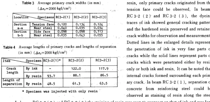
Table3
Average
primary
crack,widths{in
mm),
.
resin, onlyprimary
cracks,originatedfrom
the
(Aq.=2000kgf!cm2)
'
,.,,,
tension
face
couldbe
obseryed.In
beams
'
,RC3-2
(2)'
andRC3-2
(3),
the
dyeing
-traces
ofink
showed
gener,al
crackingpattern
'
and
the
hardened
resinpTeserved
and retained,
.
crack widthsfor
observation
and
measurement.,/
'TaPie4
,.,,
,
,
Do,tted
lines
in
,the
enlarged
details
represent(AinVel?lgi;i(eAntLll-liS20ofo6Prkigrnf:[YmC,laflr..F
and'iengthS OfSeParatiOn.
,the
penetration
,of
ink
in
,very
fine
parts
of.
・・
.,.
..,cracks
whileth.e
solidlines
representparts
ofcracks
whieh
were
penetrated
either・
by
,resip,
,., only orbp,tb
ink
and resi,n.It
canbe
notedthat
,
internal
cracks.formed su;roundingeach
pri,m:
ary
crack,・
In
bea.m
RC
3-2
(
l
),
separation of-
Specimen
wasinje'cted
with oniy resin'qOnCrete
frOM
reinforcing
steel cogldbe
'
obseryedas
staining
o{ resin alongthe
steelrecess.
-In
beams
RC
3-2
(
2
)
and
RC
372
(
i
)
the
staining of resin was,seentb
overcoat
onthat
ofink
and,was
less
extensive,
suggestingthat
ink
penetrated
muchbetter.
The
hatched
areas repreSentthe
separation areasjudged
through
resin.penetration whichhas
minimum
clearance of mostprobably
O,O05-O.Ol
mm.Primary
cracksTable
3
shows average widths ofprimary
crhcks measuredthrough
the
resinpenetration.
The
data
indicate
that
the
average crack widths werein
the
rangeof
O.
120-O.
134
mm ando.
o98-O.
113
mm attension
faces
and sidefaces
ofthe
'
three
beams,
respectively,The
average
crack
width adjacentto
the
steel surface was approximarelyO.
04s
mm.It
can
be
thought
that
measurements ofprimary
clacks
obtained
from
these
beams
ofdifferent
injection
methods conformedvrith
each other welL,,.
.
.
,
'
'
'Table4shows
the
averagelengths
ofprimary
cracks and,lengths'of separation of concfetefiom
reinforcing/
'
steel.
Crack
lerigth'stands
for
the
Iength'bf
prim'ary
crackineasured
through
ink
of resinpenetration
from
tension
fac'e
o{the
beam
to
apex
ofthe
crack.'
"'
'
'
tt
1
It
waspreviously
anticipatedthat
cracklength
andlength
of
separation
wouldbe
longesC
in
b'earn
RC
3-2
(
2
)
due
to
the
reloading effect, and shortestin
beam
RC
3-2
(
3
>
due
'to
the
absence ofinternal
vacuurn suetion.But
Table
4
indicates
that
there
wtis only alittle
difference
in
cracklerigths
between
the
two,
and
the
average
length
'
of
separation wastinexpectedly
longest
in
beam
RC
3-2
(
3
>.
The
latter
waspossibly.
due
to
randomfQrmation
of/
1cracksi
It
canbe
thought
that
reloadinghad
less
effects andthe.penetrability
of resin ofMethod3
(double
injection
">
wagcomparable
to
the
othersin
kpite
efthe
'ab'sence
of
internal
vacuum suption.・・・・'
,
//t/
/.ma-2{1}
Locatien
ec±mensRC3-2(1)HC3-2{2)RC3-2(3)Sectiona-aTensienfaceO;120Oi134O.124
Nearsteele.o4oO.035O.034Sidefaeee.
. .Sectienb.bNearsteelO.035O.043O.055
Item
SpecimenRC3-2(1)-RC3.2(2)RC3-2(3)
CrackiengthByink
.
122.0 117.9'Bres
±n93.788.1
,86.5
Lengthof
separationByresin48.5・61.3'.,63.,5
.2D
Ev
.ISfiP.3".
.10:U
'.05
.20
E-;
.tse.;s.
.lo:U.05
`Zos-.issPA)-ti
.10:v.05
'
E'ABC D・,E
O,ABCDE
eABC
,
t.t
Various stages
.
・
Varieus steges. Varieus,t.
tt
'
Varieus stages- A:After ink injection, B:After resin injeet ±on
e:eefore unleading
.
DtAfter unloaaingE:After splitting
Fig.
11
Changes
in
crack width at sidefaggs/in,various
stages(Exp.2>
DE stages
/
t//
t
tt
ttt/t
1'
'
'.t
''tt
-30-NII-Electronic Library Service
Injecting
pressure
and retainability of resin'
'
Fig,11
shows changesin
primary
crack widthsat
side
faces
ofthree
beams
at'varieus stages oftest
The
changes
ofdata
from
stageA
to
B
ofbeams
RC
3-2
(
2
)
and
RC
3-2
(
3
}
were slightlydifferent,
In
beam
RC
3-2
(2)
crack
widths
in
stageB
wereincreased
alittle
from
stageA,
whereasin
beam
RC3-2
(3)
such
phenomenon
could
notbe
observed.This
difference
arisedpossibly
due
to
some reloading effects.Although
the
injecting
pressure
foT
resin was5,O
kgflcmZ
which was muchhigher
than
that
ofink
injection,
the
magnitudedid
not affectto
increase
crack widths.The
data
in
Fig.
11
alsoindicate
that
there
was somedecrease
in
crack widthsin
ttnloading
stage
D
which was relatively small andhad
similartendency
amongthe
three
beams.
As
a matter offact,
Methods2
and3
wereboth
applicable.Although
the
penetrability
of resin was relativelysame
among
the
three
methods,Method
3
was morepractical
than
Method
1
and much simplerthgn
Method
2.
Therefore,
Method
3
is
proposed
for
the
investigation
of
this
subject,
'
5.
Conclusions
This
paper
describes
a newinjection
test
technique
for
investigation
ofinternal
crackingof
concrete
members such aspartially
prestressed
concreteand
reinforced concrete.Results
from
the
conventionalinjection
test
indicated
that
if
ink
orresin
alone
is
injected
into
cracks ofa specimenthe
crackpattern,
sizes and shapes ofthe
cracks
can notbe
obtaineddirectly
andtogether
asthey
are.An
idea
was conceivedin
trying
to
inject
both
ink
and
resin oneby
oneinto
the
same specimen, andthe
methodis
called"double
injection
technique".
The
test
maybe
conductedin
two
ways;oneis
te
untoadthe
beam
afterink
injection
and reloadit
to
utilizethe
internal
vacuum suction andthe
otheris
to
inject
resin afterink
without unloadingthe
beam
in
orderto
ayoid any reloadingeffects,
The
examination was consequentlydone
and
the
results maybe
summarized asfollows
:
(
a)
Checking
changesin
surface crack widths confirmedthat
reloading effects may enlargeprimary
crack widthsto.some
extent(b)
The
absence ofinternal
vacuum suctionin
the
double
injection
(double
injection
E)
does
not affectthe
penetrability
of resin.(c)
Injecting
pressure
of5.
0kgffcm2
for
resininjection
in
this
study
does
not affectthe
cracking conditions,(
d
)
The
double
injecting
methodproposed
in
this
paper
which
does
not Tequire unloading work seemsto
be
one
of
the
mostpractical
and reliabletechnique
for
the
investigation
ofinternal
6racking
of concrete members.References
l)
Iilston,
J.
M.
andStevens,
R.F.
:Internal
Cracking,
J.
Concrete,
Jul.
1972,
pp.
28-31.
2}
BToms,
B.B.
:
Technlque
for
Investigation
ofInteinal
Cracks
in
Reinfercedi
Concrete
Members.
J.
ACI62,
Jan.
1965,
![Fig. 4 Loading &, a[rangemgnt of in]ection <E,xp. 1)](https://thumb-ap.123doks.com/thumbv2/123deta/9880927.989609/3.892.434.810.91.599/fig-loading-amp-rangemgnt-ection-lt-e-xp.webp)