SuperKEKB に向けた高位置分解能 Linac BPM 読み出しシステムの開発
DEVELOPMENT OF HIGH POSITION RESOLUTION LINAC BPM READOUT SYSTEM
TOWARDS THE SUPERKEKB
一宮 亮#, A), 諏訪田 剛A), 佐藤 政則A) , 宮原 房史A), 古川 和朗A)
Ryo Ichimiya #, A), Tsuyoshi SuwadaA), Masanori SatohA) , Fusashi MiyaharaA), Kazuro FurukawaA) A) KEK
Abstract
The SuperKEKB accelerator is now being upgraded to bring the world highest luminosity (L=8x1035/cm2/s). In order
to archive this, electron/positron emittance has to be 20 mm mrad for each beams. To realize them, accelerating structures have to align within 0.1 mm. To perform Beam Based Alignment effectively, Beam Position Monitors (BPMs) are essential instruments and required to have one magnitude better position resolution than required alignment accuracy. To attain <10 μm position resolution, we employed band pass filter (BPF), dedicated readout system with 250 MSa/s 16 bit pipeline ADCs.
This BPM readout system has to have not only high position precision (σ <10 μm), but also precise position accuracy, which have to be within position precision range. There are many error source of position accuracy; BPM input channel gain drift during operation is one of the major error sources. To compensate this, a calibration tone generator is implemented. System linearity is also essential parameter; non-linearity is dominant error source for both precision and accuracy. Therefore, we designed the system has non-linearity within ±0.02 dB and set an appropriate operation point. Based on these design, we have fabricated a prototype BPM readout (named 18K12A) and performed several tests including 3-BPM measurement.
1. はじめに
KEK 電子・陽電子入射器(以下入射器と称す)では、 世界最大ルミノシティを目指した SpuerKEKB[1]加速 器に向けて高度化を進めている。L = 8x1035 /cm2/s を 達成するためには、電子及び陽電子エミッタンスを ともに 20 mm mrad にする必要がある。これを実現 するためには、ビーム光学設計上、0.1 mm 以内に加 速管をアライメントしなければならない。安定して Beam Based Alignment を行うためには、ビーム位置 モニター(Beam Position Monitor: 以下 BPM)には必要 なアライメント精度よりも一桁高い位置分解能が求められる。位置分解能 10 μm 以下を達成するため、
バンドパスフィルタ(Band Pass Filter: 以下 BPF)方式
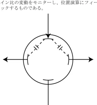
[2]を採用し、250 MSa/s・16bit パイプライン ADC を 用いた専用読み出しシステムを新規に設計・開発し た。 BPM 読み出しシステムは高い位置精度(σ < 10 μm) を確保するだけではなく、同時に位置精度と同程度 以上の位置確度を持たなければならない。位置確度 の誤差要因としては様々な理由が考えられるが、各 BPM からの入力チャンネルゲインの時間的ドリフト によるものは主要な要因の一つである。この効果を 補償するため、校正信号発生装置を読み出しシステ ム内に実装した。これは、ビーム入射の間に BPM の一電極に対して校正パルスを与えることにより、 それに隣接する一対の対向電極に電極間容量を通じ て均等な模擬パルスを誘起させ(Figure 1 参照)、その 出力パワーをそれぞれ算出する事で、チャンネル間 ゲイン比の変動をモニターし、位置演算にフィード バックするものである。
Figure 1: BPM calibration scheme is illustrated. Calibration tone is provided to the top electrode and induced pulses are generated on both adjacent electrodes with coupling capacitance.
一方で、BPM 読み出しシステム全体には高い線形 性が求められる。非線形性は位置確度とともに位置 精度にも影響を及ぼす枢要なパラメータである。 従って我々は系全体の非直線性を±0.02 dB 以下にな るように設計し、適切な動作点を設定した。 これらの設計に基づき、新 BPM 読み出しシステ ___________________________________________ # [email protected]
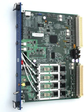
ムのプロトタイプ(写真を Figure 2 に示す)を製作し、 3-BPM 試験を含む評価を行った。
Figure 2: Photograph of prototype of BPM readout board (called 18K12A) is shown. This is double width module. BPF-Amp board is attached on bottom of the main (ADC) board. The output from BPF-Amp is fed to main board via four coaxial cables.
2. ハードウェアの実装
ハードウェアの基本設計については昨年度の本学
会で報告[3]した通りなので、ここでは昨年度の一次
試作からの変更点について主に記す。 Table 1: Design Difference
変更点 一次試作(18K12) 二次試作(18K12A) BPF 周波数 300 MHz 180 MHz BPF 構成 ヘリカルコイルに よるBessel フィル タ+アンチエイリ アシングフィルタ LC による狭帯域 Bessel フィルタと 広帯域Butterworth フィルタの組み合 わせ 校正装置出力 36 dBm 以上 40 dBm 以上 ADC Clock AT カット SAW 型(低ジッタ) Clock delay 有り 無し(を評価) ADC Input RF Amp によるア
クティブ方式。 トランスによる パッシブ方式 前 章 で 議 論 し た よ う に 、 目 標 と す る 位 置 精 度 (σ < 10 μm)を達成するためには歪みなく線形に信号 を伝送する必要がある。開発の過程でその支障に なっていたのは以下の点である事が分かった。 まず、ヘリカルコイルは微妙な調整が必要であり、 高線形性を要求する用途には向かない。従って透過 中心周波数を180 MHz に下げ、通常の LC フィルタ にした。LC フィルタの構成としては、Figure 3 に示 すように2 段構成にした。後段の C 結合 Bessel フィ ルタにて、帯域(22 MHz)、バースト長(約 60 ns)など 特性を出し、Bessel フィルタの緩やかな遮断特性を 補うために前段の広帯域(60 MHz)な Butterworth フィ ルタで裾を切った。これによりBessel フィルタによ る良好な群遅延特性を保ちつつ、ADC(fs=250 MHz,
AD9467-250[4])の 2nd Nyquist window(125 MHz –
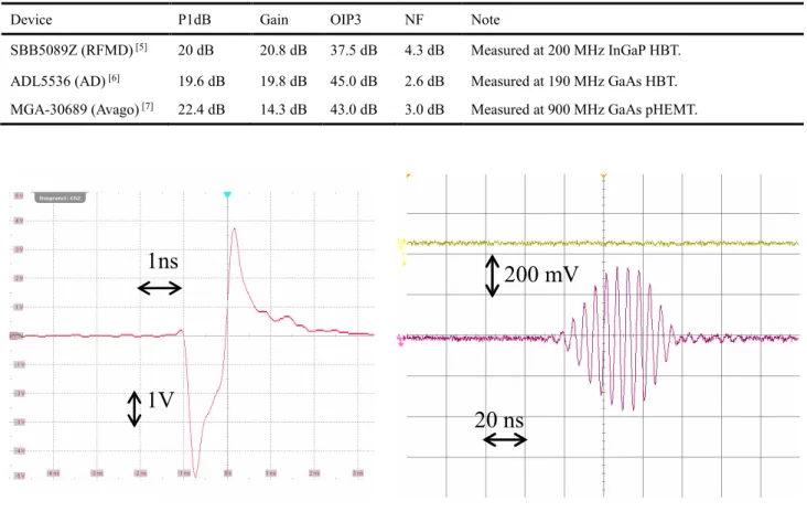
250 MHz)端では 40 dB 以上の遮断特性を確保し、折 り返し雑音を抑制した。 また、BPF 回路での後段増幅器は ADC に入力する 信号レベルを決定するものであり、その線形性が全 体の線形性を支配する事が分かっている。そのため、 Table 2 に示すように 3 種類の高周波 Amp 素子を試 験した。結果、Figure 3 に示すように OIP3 の高い
Analog Devices (AD)が最も高い線形性を示すものの、
Figure 3: Block diagram of Band Pass Filter circuit (shown 1 channel). It equips calibration tone input selector. First Butterworth filter (60 MHz) cut tails that exceed ADC’s Nyquist window (125 MHz – 250 MHz) and second Bessel filter (22 MHz) forms total bandwidth and burst length (60 ns). Each stage has an electrical attenuator and an amplifier to set an adequate level.
Figure 4: Amplifier linearity curve in the BPF circuitry is shown. AD shows wide linearity but has rapid dropout at high level. Avago shows moderate characteristics.
Table 2: Amplifier Comparison
Device P1dB Gain OIP3 NF Note
SBB5089Z (RFMD) [5] 20 dB 20.8 dB 37.5 dB 4.3 dB Measured at 200 MHz InGaP HBT. ADL5536 (AD) [6] 19.6 dB 19.8 dB 45.0 dB 2.6 dB Measured at 190 MHz GaAs HBT. MGA-30689 (Avago) [7] 22.4 dB 14.3 dB 43.0 dB 3.0 dB Measured at 900 MHz GaAs pHEMT.
(a) Beam waveform from BPM (0.8 nC single bunch). (b) BPF output waveform. Figure 5: BPF input waveform (a) and output waveform (b) are shown.
あるレベル以上で急激に低下する特性であった。こ れは、ビームが想定範囲(±5 mm)以上に大きく変位 して通過した時に過大な位置確度の劣化をもたらす 可能性があり、そのため AD より特性は劣るものの 穏やかな特性を示す Avago を選定した。これを用い て実際のビームを通した特性を Figure 5 に示す。 BPF の LPF 特性により約 60 ns の長さにビーム信号 が引き延ばされており、これにより 96 ns 間隔 2 バ ンチ入射に対応しつつ、250 MSa/s の ADC で多くの サンプル点を確保する事が出来る。 また、ADC の入力回路は当初 RF Amp を用いた パッシブ回路にしていたが、これが ADC 入力のダ イナミックレンジを制約している事が分かり、二次 試作ではトランスを用いたパッシブ方式に変更した。 さらに、16 bit ある ADC の出力ビット数のうち、
有 効 と な る ビ ッ ト 数(Effective Number Of Bits: ENOBs)を増やす事が高位置分解能に寄与するため、 次のような対策を採った。 1. ENOBs にはクロック信号源のジッタが大きく 影響する事が知られている。そのため、ADC に供給する 250 MHz クロック源を通常の AT カットの水晶発振子から、低ジッタの SAW 型 水晶発振子に変更した。 2. 同じ理由により、ADC に供給するクロックの 位相を微調整する遅延チップをバイパスさせ て試験した。 最後に、校正信号発生装置の出力を増加させ、通 常BPM(電極内径 ϕ = 27 mm, 電極長 l = 132.5 mm)よ り も 内 径 の 大 き い 陽 電 子 用 BPM( 電 極 内 径 ϕ = 63 mm, 電極長は同じ)[8]であっても、良好な S/N を得られるようにした。
3. 性能評価試験
3.1 線形性・分解能チェック BPM 読み出しシステムの線形性及び分解能を評価 するため、Figure 6 のようなセットアップにて試験 を行った。信号源としてビームを模擬したインパル スジェネレータの代わりにSG からの 180 MHz 正弦 波を用いた。これは信号源由来のノイズやジッタを 可能な限り低減するためで、パルス入力をした時と 同じ条件となるよう、ADC 出力を 96 ns の Hanning 窓で切り出して用いた。信号レベルの正確性はこの 測定の肝であり、そのために 0.03 dB の再現性のあるAgilent J7211B Step Attenuator をネットワーク・ア ナライザで校正して用いた。
1ns
1V
200 mV
Figure 6: Linearity / Resolution test setup. SG output is equality divided to four channels to emulate ideal beam pass through center of BPM. Agilent J7211B step attenuator has 0.03 dB insertion loss repeatability. We calibrated it with a network analyzer.
Figure 7: Upper plot shows BPM readout system resolution at ideal condition. Lower plot shows system linearity: we have 11 dB of ±0.02 dB linearity range.
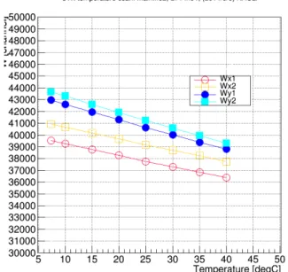
Figure 7 に示すのはこの方法で取得した位置分解 能(上)と各チャンネルの線形性(下)である。理想的な 条件においては、最大で 1 μm 程度の位置分解能が 得られている事が分かる。しかしながら、実際には ビームは BPM 中心から外れて入射しうるため、対 向電極のうちビームが近い側の信号レベルが高くな り、反対側は低くなる。そのため、動作点としては 条件を満たす範囲の中心付近に設定する事が必要と なる。我々が必要とする条件は、 1. 位置分解能が10 μm 以内の領域 2. 線形性が0.02 dB の領域 である。Figure 7 においてその領域は 11 dB 確保さ れており、その時の分解能は約2 μm である。 3.2 温度係数について 一般に電子回路を構成する能動素子・受動素子と もに温度による特性変化を示す。特に増幅器は比較 的大きな負の温度係数を持つ事が知られている。 BPM 読み出しシステムで求めるパラメータ ビーム位置 ビーム電荷 のうち、ビーム位置は算出式にて概ねチャンネルパ ワーW(各チャンネルのビームパルス信号を ADC し たものを二乗和平方根したもの;ビームパワーに比例 する)の影響をキャンセルしてくれるが、ビーム電荷 はそのまま影響を受ける。そのためその影響を見積 もるため、チャンネルパワーの温度係数を測定した。 Figure 8 に測定結果を示す。各チャンネルとも チャンネルパワーの絶対値に違いがあるものの、ほ ぼ等しい温度係数を持つ。 ここから求まる温度係数は、-0.3% / ℃であった。 BPM 読み出しシステムが設置されるクライストロン ギャラリーでの温度変動が最大でも 0.5 ℃であるの で、電荷量の変動は 0.15%となる。これは運転上全 く問題ないレベルである。
Figure 8: Temperature coefficient of channel power W is shown. Vertical axis is channel power W and horizontal axis is temperature. DUTs were stored in a thermostatic chamber. Measurements were done from low temperature to high temperature. 3.3 3-BPM 試験 これまでの測定で実験室においては、本 BPM 読 み出しシステムが目標とする特性を示す事が確認さ れた。本システムを量産しインストールするための 決断を下すためには、実際に用いられる加速器にお いて、ビームを用いた試験を行う必要がある。
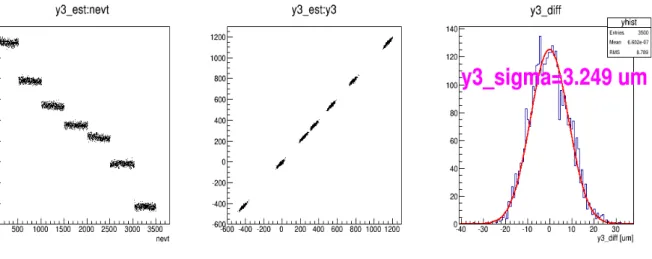
Figure 9: Left plot shows estimated position vs. event number. Center plot shows estimated position vs. actual position. Right plot shows histogram of estimated position – actual position.
そこで、KEK Linac にて 3T 熱電子銃からのビー ム(0.8 nC)を用いて、3-BPM 試験[9]を行った。使用し た BPM は、下流部の連続する 3 個(SP52-4, SP54-4, SP56-4)を用いた。 線形ラティスを仮定すると、任意の3 箇所の BPM 位置x1, x2, x3は と与えられる。ここで、N 回の試行により N 組の (x1, x2, x3)より重回帰分析により(A, B, C)を求める事 が出来る。従って各測定点との残差の二乗平均は、 と与えられる。(Figure 9 の右図に対応) これから位置分解能は 3 台の BPM の位置分解能が 一定と仮定すれば、位置分解能は、 と与えられる[9]。 この原理を用い、3 台の BPM の上流のステアリン グマグネットの磁場を変化されてビーム位置を y 方 向に振り(Figure 9 の左図参照)ながら、12.5 Hz にて 3500 イベントのデータを取得した。 結果、上式により位置分解能は3.25 μm を得た。
4. まとめと今後の計画
位置分解能及び位置確度が 10 μm 以下であり、経 時位置ドリフトを校正信号発生器により補償する BPM 読み出しシステムを開発した。目標を達成する ためには高い線形性と安定性が必須であり、様々な 工夫でこれを克服した。 今年度中に約 100 台の量産を行い、来年夏の長期 Shutdown にて投入予定である。謝辞
SLAC の Steve Smith 氏、Andrew Young 氏、KEK
の飛山 真理氏には詳細なアドバイスと助言を頂いた。
また、デジテックス研究所の山田 恭介氏と三光社の
土屋 文武氏、青山 森繁氏には基板設計・製造を
行って頂いた。ここに深く感謝する。
参考文献
[1] M. Masuzawa, in Proceedings of the First International Particle Accelerator Conference (IPAC’10), Kyoto, 2010, pp. 4764–4768.
[2] S. R. Smith et al., “LCLS Stripline BPM System Commissioning”, in Proceedings of the 23rd Particle Accelerator Conference (PAC’09), Vancouver, Canada, 2009, pp4027-4029.
[3] R. Ichimiya et al., “SuperKEKB に向けた電子・陽電子 Linac 用ビーム位置モニターの読み出しシステム開発”, 第 10 回日本加速器学会年会プロシーディングス, 名 古屋大学東山キャンパス, 2013, pp191-193.
[4] Analog Devices, 16-bit, 200 MSPS/250 MSPS Analog-to-Digital Converter AD9467 Data Sheet :
http://www.analog.com/static/imported-files/data_sheets/AD9467.pdf
[5] RFMD, 50 MHz to 6000 MHz, Cascadable Active Bias InGaP HBT MMIC Amplifier SBB5089Z Data Sheet: http://www.rfmd.com/CS/Documents/SBB5089ZDS.pdf [6] Analog Devices, 20 MHz to 1.0 GHz, IF Gain Block
ADL5536 Data Sheet:
http://www.analog.com/static/imported-files/data_sheets/ADL5536.pdf
[7] Avago Technologies, 40 MHz to 3000 MHz, Flat Gain High Linearity Gain Block MGA-30689 Data Sheet: http://www.avagotech.co.jp/docs/AV02-1876EN
[8] T. Suwada et al., “Stripline-type beam-position monitor system for single-bunch electron/positron beams”, Nuclear Instruments and Methods in Physics Research A 440, pp.307-319 (2000). [9] 諏訪田 剛, “ビーム計測 I”, OHO 2002 (2002). 𝜎𝜎2= 1 𝑁𝑁 �{𝑥𝑥3𝑛𝑛− (𝐴𝐴𝑥𝑥1𝑛𝑛+ 𝐵𝐵𝑥𝑥2𝑛𝑛)}2 𝑁𝑁 𝑛𝑛=1 𝜎𝜎𝑥𝑥= � 𝜎𝜎 2 1 + 𝐴𝐴2+ 𝐵𝐵2 𝑥𝑥3= 𝐴𝐴𝑥𝑥1+ 𝐵𝐵𝑥𝑥2+ 𝐶𝐶