精密機械カンパニー
東京本社
〒105-8315 東京都港区海岸1丁目14-5 Tel. 03-3435-6862 Fax. 03-3435-2023
神戸本社
〒650-8680 神戸市中央区東川崎町1丁目1-3(神戸クリスタルタワー)
Tel. 078-360-8605 Fax. 078-360-8609
西神戸工場
〒651-2239 神戸市西区櫨谷町松本234番地
Tel. 078-991-1133 Fax. 078-991-3186
福岡営業所
〒812-0011 福岡市博多区博多駅前1丁目4-1(博多駅前第一生命ビルディング9F) Tel. 092-432-9561 Fax. 092-432-9566
東京サービスセンター
〒272-0015 千葉県市川市鬼高4丁目9-2 Tel. 047-379-8181 Fax. 047-379-8186
今治サービスセンター
〒794-0028 愛媛県今治市北宝来町1丁目5-3(ジブラルタ生命ビル、川重商事内)
Tel. 0898-22-2531 Fax. 0898-22-2183
福岡サービスセンター
〒811-0112 福岡県粕屋郡新宮町下府2丁目10-17 Tel. 092-963-0452 Fax. 092-963-2755
http://www.khi.co.jp/kpm/
Cat. No. KPM1409 Sep. '14 S 精密機械カンパニー
Kawasaki Precision Machinery (UK) Ltd.
Ernesettle Lane, Ernesettle, Plymouth, Devon, PL5 2SA United Kingdom Phone +44-1752-364394 Fax. +44-1752-364816
http://www.kpm-eu.com
Kawasaki Precision Machinery (U.S.A.), Inc.
3838 Broadmoor Avenue S.E. Grand Rapids, Michigan 49512, U.S.A. Phone +1-616-975-3100 Fax. +1-616-975-3103
http://www.kpm-usa.com
Kawasaki Precision Machinery (Suzhou) Ltd. 668 JianLin Rd, New District, Suzhou, 215151 China Phone +86-512-6616-0365 Fax. +86-512-6616-0366
Kawasaki Precision Machinery Trading (Shanghai) Co., Ltd.
17th Floor (Room 1701), The Headquarters Building, No168, XiZang Road (M), Huangpu District, Shanghai, 200001, China
Phone +86-021-3366-3800 Fax. +86-021-3366-3808 Kawasaki Chunhui Precision Machinery (Zhejiang) Ltd.
No.200 Yasha Road Shangyu Economic Development Zone, Shansyu, Zhejiang, 312300, China
Phone +86-575-8215-6999 Fax. +86-575-8215-8699 Flutek, Ltd.
98 GIL 6, Gongdan-Ro, Seongsan-Ku, Changwon-Si, Kyungnam,641-370, Korea Phone +82-55-210-5900 Fax. +82-55-286-5557
Wipro Kawasaki Precision Machinery Private Limited
No. 15, Sy. No. 35 & 37, Kumbalgodu Industrial Area, Kumbalgodu Village, Kengeri Hobli, Bangalore, – 560074 ,India
Tokyo Head Office
1-14-5 Kaigan, Minato-ku, Tokyo 105-8315, Japan Phone +81-3-3435-6862 Fax. +81-3-3435-2023 Kobe Head Office
Kobe Crystal Tower, 1-3 Higashikawasaki-cho 1-chome, Chuo-ku, Kobe 650-8680, Japan
Phone +81-78-360-8607 Fax. +81-78-360-8609 Nishi-kobe Works
234, Matsumoto, Hasetani-cho, Nishi-ku, Kobe 651-2239, Japan Phone +81-78-991-1160 Fax. +81-78-991-3186
Precision Machinery Company
OVERSEAS SUBSIDIARIES http://www.khi.co.jp/kpm/
一般産業機械用
アキシャルピストンポンプ
Axial Piston Pumps
for General Industrial Machinery
このカタログに記載の内容は、改良のため予告なく改訂・変更する場合があります。
SAFETY PRECAUTIONS
Before you use the product, you MUST read the operation or operators manual and MUST fully understand how to use the product. To use the product safely, you MUST carefully read all Warnings and Cautions in this manual. You MUST also observe the related regulations and rules regarding safety.
Use the safety equipment to avoid the in-jury when you operate the product.
Pay enough attention on handling method to avoid pinching hands or back problems that may be caused by heavy weight of the product or handling posture.
Installation, removal, plumbing, and wir-ing must be done by the certified person.
*CERTIFIED PERSON : a person who has enough knowledge like a person who is trained by Kawasaki’s hydraulic school.
Make it sure that the power of the hy-draulic power unit is turned off and that the electric motor or engine has complete-ly stopped before starting installation or removal. You must also check the system pressure has dropped to zero.
Do not step on the product, hit it, drop it or give strong outside force to it, as one of these actions may cause the failure of work, damage or oil leakage.
Wipe the oil on the product or floor off completely, as the oil creates slippery conditions that may result in dropping the product or injuring.
Cautions related to operation
Warnings and Cautions related to installation and removal of the product
Turn off the power before starting wiring or other works related to the electric pow-er, otherwise you may be stuck by an electric shock.
Use the specified bolts and keep the spec-ified tightening torque when you install the product. Usage of unauthorized bolts, lack of torque or excess of torque may create problems such as failure of work, damage and oil leakage.
Clean the threads and mounting surface completely, otherwise you may experi-ence damages or oil leakage caused by in-sufficient tightening torque or broken seal.
Never use the product not equipped with anti-explosion protection in the circum-stances of possible explosion or combus-tion.
Shield the rotating part such as motor shaft and pump shaft to avoid injuries caused by being caught of fingers or cloths.
Stop the operation immediately if you find something wrong such as unusual noise, oil leakage or smoke, and fix it properly. If you continue operating, you may encoun-ter damage, fire or injury.
Warnings and Cautions for operation Never modify the product without approval of Kawasaki.
Do not disassemble and assemble with-out approval by Kawasaki. It may cause troubles and failure, or it may not work as specified. If it is necessary by all means to disassemble and assemble, it must be done by an authorized person.
Keep the product from dust and rust by paying attention to the surrounding tem-perature and humidity when you trans-port or store the product.
Replacing the seals may be required if you use the product after long time stor-age.
Use the product under the specification mentioned in the catalog, drawings and specification sheet.
Keep your body off the product during the operations as it may become hot and burn your body.
Use the proper hydraulic oil, and main-tain the contamination in the recommen-ded level, otherwise it may not work or be damaged.
Make it sure that plumbing and wiring are correct and all the connection is tightened correctly before you start operating, espe-cially if it is the first run.
CAUTION
CAUTION CAUTION
CAUTION
CAUTION
WARNING
DANGER
WARNING
WARNING WARNING
CAUTION
CAUTION
CAUTION
CAUTION
CAUTION
CAUTION
CAUTION
CAUTION
CAUTION
CAUTION
安全上の注意事項
本カタログの製品を安全にご使用いただくために、下記「製品使用についての注意」や、当該製品の取扱説明書を十分にご理解いただくとと もに、以下関連規格の安全に関する法規類を必ず遵守の上、お取扱いください。
[安全に関する関連規格] 高圧ガス取締法
労働安全衛生法
JIS B 8243 圧力容器の構造 JIS B 8361 油圧システム通則
(1)製品を取り扱う時の注意事項
(2)製品の取り付け、取り外し時の注意事項
注意 製品を取り扱う際にけがをすることがありま
すので、状況に応じて保護具を着用してくだ さい。
注意 製品の重量、作業姿勢によっては、手を挟
んだり腰を痛めたりすることがありますので、 作業方法に十分注意してください。
注意 製品に乗ったり、叩いたり、落としたり、外力
を加えたりしないでください。作動不良、破損、 油漏れなどを起こすことがあります。
注意
危険
警告
警告
製品や床に付着した作動油は十分にふき取っ てください。製品を落としたり、すべってけが をする恐れがあります。
注意 取り付け、取り外し、配管、配線などの作業は、
専門知識のある方が行なってください。 *専門知識のある方:油圧調整技能士2級
程度、または当社のサービス研修を受けた 方。
警告 作業を行なう際には必ず装置の電源を切り、
電動機、エンジン等が停止したことを確認し てください。また、油圧配管内の圧力が「0」 圧であることも確認してください。
警告 電気配線工事は必ず電源を切ってから行なっ
てください。感電する恐れがあります。
注意 取付穴、取付面を清浄な状態にしてください。
ボルトの締めつけ不良、シール破損により、 破損、油漏れなどを起こす恐れがあります。
注意 製品を取り付ける時は必ず規定のボルトを
使用し、規定のトルクで締めつけてください。 規定外の取り付けをすると作動不良、破損、 油漏れを起こすことがありますので注意して ください。
(3)運転時の注意事項
(4)保守・保管上の注意事項
製品はカタログ、図面、仕様書などに記載さ れた仕様以外で使用しないでください。 運転中、製品は油温やソレノイドの温度上 昇などにより高温になりますので、手や体が 触れないように注意してください。やけどの 恐れがあります。
作動油は適正な物を使用し、汚染度も推奨 値で管理してください。作動不良、破損の恐 れがあります。
お客様による製品の改造は、絶対にしない でください。
製品は断りなく分解、組み直しをしないでくだ さい。定められた性能を発揮できず、故障や 事故の原因になります。やむを得ず分解、組 み直しをする場合は専門知識のある方が行なっ てください。
製品を運搬、保管する場合は、周囲温度、 湿度など環境条件に注意し、防塵、防錆を保っ てください。
製品を長期保管後に使用する場合には、シー ル類の交換を必要とする場合があります。 爆発または燃焼する危険性のある雰囲気
の中では、対策を講じた製品以外は絶対に 使用しないでください。
ポンプやモータなどの回転軸の保護カバー は必ず付けたままとし、手や衣類などの巻き 込みを防止してください。
異常(異音、油漏れ、煙など)が発生した場 合は直ちに運転を停止し、必要な処置を講 じてください。破損、火災、けがなどの恐れが あります。
初めて装置を運転する場合は油圧回路、電 気配線が正しいこと、および締結部に緩み がないことを確認した上で運転してください。
注意 注意 注意 注意
注意
注意
注意
注意
関連法規についての注意
製品使用についての注意
消防法 防爆等級
この製品のご採用、ご使用にあたって ・・・・・・・・・・・・・・・・・・・・・・・・・・・1 安全上の注意事項 ・・・・・・・・・・・・・・・・・・・・・・・・・・・・・・・・・・・・・・・・・・・2 アキシャルピストンポンプのバリエーション ・・・・・・・・・・・・・・・・・・・・・3
高圧・低騒音 斜板形
K3VGシリーズ ・・・・・・・・・・・・・・・・・・・・・・・・・・・・・・・・・・・・・・・・・・・・・5 電気−油圧サーボレギュレータ K3VG“ILIS”・・・・・・・・・・・・・・・15
圧力一定・ロードセンシング対応形 斜板形å
K3VLシリーズ ・・・・・・・・・・・・・・・・・・・・・・・・・・・・・・・・・・・・・・・・・・・・・23
斜板形アキシャルピストンポンプ
K7VGシリーズ ・・・・・・・・・・・・・・・・・・・・・・・・・・・・・・・・・・・・・・・・・・・・・37 取扱い上の注意(K3VG/K3VL/K7VGシリーズ)・・・・・・・・・・・41
超高圧・可変容量 斜軸形
LVP 017 ・・・・・・・・・・・・・・・・・・・・・・・・・・・・・・・・・・・・・・・・・・・・・・・・・・44
可変・固定容量 斜軸形
LZ・LZV/LX・LXVシリーズ ・・・・・・・・・・・・・・・・・・・・・・・・・・・・・・・45 取扱い上の注意(LZ・LZV/LX・LXVシリーズ)・・・・・・・・・・・・・・・61 引き合い仕様書 ・・・・・・・・・・・・・・・・・・・・・・・・・・・・・・・・・・・・・・・・・・・・64 コントローラ ・・・・・・・・・・・・・・・・・・・・・・・・・・・・・・・・・・・・・・・・・・・・・・・65 パイロット圧力制御用比例制御弁 ・・・・・・・・・・・・・・・・・・・・・・・・・・・・・66 パイロット圧力制御用圧力制御弁 ・・・・・・・・・・・・・・・・・・・・・・・・・・・・・66
ON APPLICATION / USE OF THE PRODUCTS・・・・・・・・・・・・・・・・・・・・1 SAFETY PRECAUTIONS・・・・・・・・・・・・・・・・・・・・・・・・・・・・・・・・・・・・・・・・・・2 WIDE VARIETY OF OUR AXIAL PISTON PUMPS・・・・・・・・・・・・・・・・・・3
Silent and High-pressure Swash Plate Type
K3VGSERIES ・・・・・・・・・・・・・・・・・・・・・・・・・・・・・・・・・・・・・・・・・・・・・・・・・・・・5 ELECTRO-HYDRAULIC SERVO REGULATOR K3VG“ILIS”・・・・15
Load-sensing Circuit Swash Plate Type
K3VLSERIES ・・・・・・・・・・・・・・・・・・・・・・・・・・・・・・・・・・・・・・・・・・・・・・・・・・・23
Swash-Plate Type Axial Piston Pump
K7VGSERIES・・・・・・・・・・・・・・・・・・・・・・・・・・・・・・・・・・・・・・・・・・・・・・・・・・・37 CAUTION FOR INSTRUCTION (K3VG / K3VL / K7VG SERIES)・・・・41
Super-high-pressure Bent Axis Type
LVP 017・・・・・・・・・・・・・・・・・・・・・・・・・・・・・・・・・・・・・・・・・・・・・・・・・・・・・・・・・・44
Variable / Fixed Displacement Bent Axis Type
LZ・LZV / LX・LXVSERIES ・・・・・・・・・・・・・・・・・・・・・・・・・・・・・・・・・・・・・・45 CAUTION FOR INSTRUCTION (LZ・LZV / LX・LXV SERIES)・・・・・・61 Specification studies・・・・・・・・・・・・・・・・・・・・・・・・・・・・・・・・・・・・・・・・・・・・・64 Controller・・・・・・・・・・・・・・・・・・・・・・・・・・・・・・・・・・・・・・・・・・・・・・・・・・・・・・・・・65 Proportional Pressure Control Valve for Pump Pilot Pressure・・・・・66 Pressure Control Valve for Pump Pilot Pressure・・・・・・・・・・・・・・・・・・66
page ページ
もくじ
CONTENTS
この製品のご採用、
ご使用にあたって
当社の製品は、十分な知識と長年の経験に基づいて設
計され、厳しい品質管理の下に製造していますが、ご採
用いただくにあたっては次の点にご配慮くださいますよ
うお願いいたします。
このカタログに掲載されている製品は、使用される条件が 多様なため、製品のシステムへの適合性の決定は、油圧 システムの設計者または仕様を決定する人が、必要に応 じて分析やテストを行なってから判断してください。また、常 に最新のカタログや資料で仕様を検討し、機械の故障の 可能性についての状況を考慮してシステムを構成してくだ さい。
製品のご使用にあたっては、安全上の注意事項を遵守の 上、正しい使用方法でお使いください。
このカタログに記載された技術情報は、製品の特性や性 能を説明する代表値であり、保証値ではありません。
次に示すような条件や環境でのご使用にあたっては、事前 に当社までご相談ください。
明記されている仕様以外の条件や環境。
原子力、航空、医療、食品などの用途に使われる場合。 人や財産に大きな影響が予想される用途、とくに安全
性が要求される用途に使われる場合。
本カタログに掲載された情報は、予告なしに変更される場 合があります。最新情報については、当社までお問合せく ださい。
ON APPLICATION / USAGE
OF THE PRODUCTS
The operating conditions of the products shown in this catalog vary depending upon each application. Therefore, the decision of the products' suitability to the system considered must be made by the designer of the hydraulic system and/or the person in charge of determining the specification after making analysis and conducting tests, if necessary. The study of the specification shall be done based on the latest cata-log and technical documents, and the system must be composed taking into account situations regarding the possibility of machine failure.
Prior to use of the products, descriptions given in the SAFETY PRECAUTIONS must be observed for the proper use.
The technical information in this catalog represents typical characteristics and performance of the prod-ucts, and is not guaranteed one.
In case the products are used in the following condi-tions or environments, please consult us prior to the use.
Unspecified conditions or environments
Use for atomic power, aviation, medical treatment, and/or food
Use likely to affect human beings or assets signifi-cantly or requiring particular safety
The information described in this catalog is subject to change without notice.
For updated information, please consult us.
Although our products are designed on the basis of our profound knowledge and long experience, and manu-factured under the strict quality control system, the fol-lowing must be taken into consideration in actual use.
一般産業機械用
for Industrial Applications
射出成型機用
for Injection Molding Machines
一般産業機械用・産業車両用
for Industrial Applications for Industrial Vehicles
一般産業機械用
for Industrial Applications
産業車両用
for Industrial Vehicles
オープン回路
Open Circuits オープン回路Open Circuits オープン回路Open Circuits オープン回路・クローズ回路Open Circuits・Closed Circuits オープン回路Open Circuits
シングルポンプ
Single Pump
タンデム型ダブルポンプ
Double Pump (Tandem Type)
シングルポンプ
Single Pump
シングル/ダブルポンプ
Single / Double Pump 押しのけ容積
Displacement
K3VG 63
− 40
− 50
− 60
− 110
− 140
− 180
− 280
− 360
− 560 (cm3)
K3VG 112
K3VG 180/K7VG180
K3VG 280 K7VG 265 K3VG 180DT
K3VG 280DT
K3VG 180DT(合流)
K3VG 280DT(合流)
K3VG 180
K3V63DT/K5V80DT K3VL45
K3VL28
K3VL60
K3VL80
K3VL112
K3VL140
K3VL200
LVP017
LZ・LX-030
LZ・LX-060
LZ・LX-090
LZ・LX-120 LZV120
LZ・LX-180 LZV・LXV180
LZ・LX-260 LZV・LXV260
LZ・LX-500 LZV・LXV500
K3V112DT/K5V140DT
K3V140DT
K5V200DT
K3V280DTH K5V200DTH
K3V63S/K5V80S
K3V112S/K5V140S
K3V140S
K5V200S
K5V200SH
K3V280S
K3V280SH
アキシャルピストンポンプの豊富なバリエーションの
中から、産業機械に最適なポンプをご紹介します。
Out of a Wide Variety of Our Axial Piston Pumps, We Introduce
Hydraulic components for Industrial Applications.
K3VGシリーズ K3VG Series
K3VLシリーズ K3VL Series
LZ/LZVシリーズ LZ/LZV Series
カワサキのアキシャルピストンポンプ
Kawasaki Axial Piston Pumps Programs
K3VG Series
一般産業機械に適した斜板形アキシャルピストンポンプ です。コンパクトな高効率・高信頼性・低騒音タイプの高圧 ポンプです。高精度電気油圧サーボレギュレータを始め豊 富な制御方式を揃えています。
The K3VG series swash plate type axial piston pump is high-pressure pump for industrial machinery with high efficiency, reliability and low noise. Good varieties of control methods are available as well as a highly precise electro-hydraulic servo regulator "ILIS".
K3VL Series
一般産業機械、産業車両用のロードセンシング、および圧 力一定の油圧回路に最適な斜板形アキシャルピストンポン プです。SAE、ISO、JIS規格に準じた取合いを有しています。 ロードセンシングと圧力一定制御を基本とし、オプションと して馬力制御も可能です。
The K3VL series pump is the swash plate type axial piston pump designed for industrial machinery and mobile corresponding to American (SAE), International (ISO) and Japanese (JIS) standard mounting. The horsepower control is possible in addition to load-sensing and pressure constant control.
K7VG Series
高圧・大流量の用途に適した産業機械用可変容量形斜板 ポンプです。独自の技術により長寿命・低騒音化を達成して います。特に製鉄機械・鍛圧機械などの重負荷に最適です。
The K7VG series pump is the swash plate type axial piston pump designed for high-pressure application with long life and low noise. This pump is especially suitable for steel making plant and press machinery.
LZ
・
LZV/LX
・
LXV Series
製鉄機械・鍛圧機械などに最適な高効率・長寿命な斜軸
形ピストンポンプです。その中でもLZV
/
LXVシリーズは軸受部をさらに強化したロングライフ形ポンプです。高圧 連続負荷状態、あるいは難燃性作動油での使用など厳しい 条件下でも長寿命を有します。
The LZ・LZV / LX・LXV series pump is suitable for the heavy duty application in the press machine and steel making plants. The LZV / LXV series pump is long life type with reinforced bearings. They can operate for long periods of time under severe conditions: high-pressure continuous drive, use of fire resistant fluid, etc.
LVP017
高圧ジャッキ・トンネル掘削機などに最適な超高圧の手 動可変容量の斜軸形ピストンポンプです。
サ イ ズ /size
押しのけ容積 /displacement cm3
圧 力 pressure MPa(kgf/cm2)
回 転 数 speed min−1
定 格 rated *1
最 高 max.
ピーク peak
定 格 rated 自吸最高*2 max. for self-priming 最 高 max. *3
サイズ size
ネジ1回転当たりの調整量 cm3
approx. displacement change per revolution of screw
最小調整吐出量 cm3
min. setting of max. displacement 作 動 油
hydraulic fluid
質 量 / mass kg
フィルト レーション filtration
種類*4 type 温度範囲
oil temperature range °C 粘度範囲*5
oil viscosity range mm2/s
洗浄度
contamination level 吸入ライン suction line 戻りライン return line
34.3(350) 34.3(350) 39.2(400)
1,800 1,200 1,800 1,200
2,600 2,200 1,850 1,600 1,850 1,600
3,250 2,700 2,300 2,000 2,300 2,000
48 68 86 160 160 300 314 559 902 1,400 1,804 2,800
鉱物系耐摩耗性油圧作動油 mineral antiwear hydraulic fluid
— 20∼80
10∼1,000
NAS 9 級以内 at least the level of NAS Class 9
150メッシュ 150 mesh ノミナル10μm nominal 10 micron meter
63 112 180 /180DT 280 /280DT
6.3
9.2
15.3
20.3
25.7
63
87
140
63 112 180 280 180DT 280DT
63 112 180 280 180DT 280DT
最大入力トルク
Maximum allowable total input torque N・m
K3VG Series
高圧・低騒音 斜板形
Silent and High-pressure Swash Plate Type
建設機械用ピストンポンプとして豊富な実績をもつK3Vシリーズポンプをベー
スとし、産業機械でのさまざまなニーズを盛り込んで開発した産業機械専用の 斜板形アキシャルピストンポンプです。定評のある高効率・高信頼性に加えて、 豊富なレギュレータを揃え、補助ポンプもオプションで取り付けられるなど、使
いやすく、堅牢で、かつ低騒音化を実現したK3VGポンプをぜひご活用ください。
The K3VG Series is a newly developed swash-plate type axial piston pump exclusively for application to industrial machinery, and has been designed based upon the K3V Series having rich experience as a pump for application to construction machines. In addition to the well-reputed high efficiency and excellent reliability, varieties of regulators and optional auxiliary pumps are available. Do try the K3VG Series that is durable and silent to your satisfaction.
1. 高圧力・長寿命
1. Reliable High-Pressure and Long-Life Type
*1
*2
*3
*4
*5
長年の豊富な経験と実績に基づいて、一般産業機械用とし て開発した斜板形の高圧ポンプです。高負荷容量の軸受、シュー の摩耗補償形押しつけ機構の採用によって、長寿命化を達成し、 高い信頼性を得ています。
This series is a high-pressure, swash-plate type pump devel-oped for general industrial machinery based upon our long and rich experience. The adoption of the high-load bearings and friction-free contacting mechanism of shoes has ach-ieved high reliability and long life.
2. 低騒音
半円筒形の斜板の採用、振動を抑制する斜板支持機構に加 えて、コンパクトで剛性の高い独特なケーシング構造によって、
騒音を低減しています。(9 ∼10ページの騒音データ参照)
さらに、当社独自のユニークな機構で圧力脈動の低減にも 成功しています。また圧力脈動吸収器(オプション)を使用
することによって、より一層の騒音低減に貢献します。(22ペー
ジの低脈動参照)
3. 高効率・高自吸性能
球面形弁板の採用と最適な油圧バランスの改良によって、 安定したシリンダの回転姿勢が得られるため、低圧・低傾転領 域まで高い効率が得られます。また、シリンダポートの半径が 小さくなり、周速が下がるため、高自吸性が得られます。
4. 豊富な制御方式
油圧・電気を入力とする豊富な制御方式を揃えています。ま た、流量制御、圧力制御、馬力制御およびそれらのあらゆる複 合制御を標準化しています。
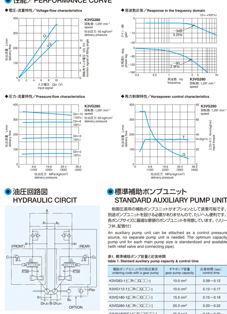
5. 補助ギヤポンプ
種々サイズのギヤポンプをオプションとして装着できます。 ポンプおよび油圧回路における制御用の低圧圧源や、作業用 の中圧圧源に別途ポンプユニットを設ける必要がなく、油圧ユ ニットのコンパクト化がはかれます。7ページの形式表示、21 ページの補助ギヤポンプ取付形状参照)
2. Low Noise
The unique compact and rigid housing construction in addi-tion to the semi-cylindrical swash-plate and its anti-vibraaddi-tion supporting mechanism has reduced noise. (See the data re-lating to noise on pages 9 and 10)
The unique mechanism has reduced pressure pulsation. Attaching the optional pressure pulsation absorber, contri-butes further system noise reduction. (See the reduced pres-sure pulsation on page 22)
3. High Efficiency and High Self-Priming Capability
The spherical valve plate and improved hydraulic balance provide stable cylinder rotation, thus achieving high efficien-cy even in a low-pressure and low-speed operating range. Besides, the shortened radius of the cylinder port lowers the peripheral speed enabling the high self-priming capability.
4. Varieties of Control Methods
Good varieties of hydraulic and electrical control methods are available. The flow control, pressure control, horsepower control, and the combination of these are standardized and available.
5. Auxiliary Gear Pump
Various sizes of optional gear pumps are attachable. Accord-ingly, no separate pump unit is necessary as control pres-sure source or as a medium-prespres-sure system prespres-sure source. Hydraulic units can thus be made compact. (See the Ordering Code on page 7 and the Installation Dimensions on page 21)
性能、機能、寿命を保証できる圧力で、強度上 問題はありませんが、軸受寿命には限界があり ます。
吸入圧力は吸入フランジ部で—0.01 MPa(—0.1
kgf/cm2)以上を確保してください。(定常状態)
吸入フランジ部で0.1 MPa(1kgf/cm2)以上
ブースト圧が必要です。
その他の作動油を使用する場合は必ずご相談 ください。
200∼1,000mm2/sの時は本格運転に入る
前に暖気運転が必要です。
*1
*2
*3
*4
*5
Pressure to allow guarantee of perfor-mance, functions and service life. Durabili-ty is unlimited (except for the bearing life). The suction pressure should be -0.01
MPa (-0.1 kgf/cm2) and above. (at normal
condition)
Minimum boost pressure at suction port
0.1 MPa (1 kgf/cm2)
When other kinds of fluid are used, please consult Kawasaki.
In case of 200∼1,000 mm2/s, please
al-low system to warm up before using at operating pressure.
球面ブッシュ
spherical bush サーボピストンservo piston バルブプレートvalve plate
最大流量調整ネジ
max. flow adjusting screw
軸受
bearing
軸受
bearing バルブカバー
valve cover
シリンダ
cylinder
ピストン
piston
シュー
shoe
押え板
set plate
斜板
swash plate
オイルシール
oil seat
駆動軸
driving shaft
斜板支持台
swash plate support
最小流量調整ネジ
min. flow adjusting screw
K3VG
Series
特長/
FEATURES
仕様/
SPECIFICATIONS
構造/
CONSTRUCTION
出荷時は、最大流量にセットしています。 Setting flow at delivery is maximum.
K3VG Series
レギュレータコード/
REGULATOR CODE
形式表示/
ORDERING CODE
K3VG 63 1 0 0 R S 1P M 1
-K3VGシリーズ
K3VG series
補助ポンプユニット (タンデムポンプ右回転のみ)
auxiliary pump unit
(only tandem and clockwise type)
無記号:補助ポンプユニット無し
blank:without auxiliary pump unit
1 : 補助ポンプユニット付
with auxiliary pump unit
取付方向
direction of mounting
− :標準仕様(軸水平方向)
standard
(horizontal mounting)
V :竪形仕様(軸端上向き)
vertical mounting
レギュレータコード(次ページ参照)
regulator code (refer to next page)
押しのけ容積
displacement
063 : 63 cm3
112 :112 cm3
180 :180 cm3
280 :280 cm3
180DT:360 cm(3 180 cm3×2)
280DT:560 cm3(280 cm3×2)
(DT:タンデム形ダブルポンプ) (DT: tandem type double pump)
合流ブロック(タンデムポンプのみ)
confluent block (only tandem type)
無記号:シングルポンプ
blank:single pump
0 :合流ブロック無し
without confluent block
S :側方吐出形
side outlet type
R :後方吐出形
rear outlet type
回転方向
direction of rotation
R :右回転
clockwise
L :左回転(タンデムポンプのみ)
counterclockwise (only tandem type)
シングルポンプには左回転はありません。
Counterclockwise is not available for the single pump.
設計コード
design code
S :
取付方法・メインポンプ付属フランジの有無
mounting type · main pump flange
0 :ブラケット無、吸吐出フランジ付
without bracket, with flange
F :ブラケット付、吸吐出フランジ付
with bracket, with flange
B :ブラケット付、吸吐出フランジ無
with bracket, without flange
N :ブラケット無、吸吐出フランジ無
without bracket, without flange
標準タイプ/Standard type
K3VG 63 1 0 0 R S 1 P M 1
-馬力セットコード
horsepower set code
馬力制御モード
horsepower control mode
H :高馬力用
for high horsepower
M :中馬力用
for middle horsepower
L :低馬力用
for low horsepower
流量制御
flow control
O :流量制御なし
without flow control
P :ポジティブ制御
positive control
N :ネガティブ制御
negative control
E :電気制御
electric control
馬力・圧力制御
horsepower/pressure constant control
0 :馬力制御なし
without horsepower control
1 :馬力制御
horsepower control
4 :圧力一定制御
pressure constant control
5 :馬力制御+圧力一定制御
horsepower and pressure constant control
(注)手動傾転制御のレギュレータコードは0000となります。
馬力制御のない場合の馬力セットコードは00となります。
(例:電気制御の場合、レギュレータコードは0E00となります)
(Note) The regulator code for the manual flow control is 0000. If horsepower is not controlled, the horsepower set code is 00. (ex. in case of electric control, the regulator code is 0E00)
(注)コントローラKIC-D24-10用のレギュレータを適用します。 旧コントローラ及び旧レギュレータ型式コード「R」との互換性 についてはお問い合わせください。
(Note) Our exclusive controller is necessary. The controller type is KIS-D24-10.
Please consalt us for old version (ORDERING CODE ''R'') compatibility.
電気−油圧サーボ ‘‘ILIS’’
/
Electro-hydraulic servo ‘‘ILIS’’K3VG 280DT - 1 0 F R S - 1 Q 1 A - R 1
補助ポンプユニット(16ページ参照)
auxiliary pump unit (refer to page 16)
0 :補助ポンプユニット無し
without auxiliary pump unit
1 :補助ポンプユニット付
with auxiliary pump unit
馬力セットコード
horsepower set code
馬力制御
horsepower controll
0 :馬力制御無し
without horsepower control
1 :馬力制御
horsepower control
制御モード
control mode
0 :馬力制御、容積効率補償無し
without horsepower control or volumetric efficiency compensation
1 :馬力制御または容積効率補償付(シングルポンプ、タンデム合流仕様)
with horsepower control or volumetric efficiency compensation (single or tandem confluent)
2 :馬力制御または容積効率補償付(タンデムポンプ個別制御)
with horsepower control or volumetric efficiency compensation (tandem independent)
流量制御
flow control
Q : ILIS—regulator
合流ブロック有無
(タンデムポンプのみ、前ページ参照)
confluent block (refer to last page)
作動油の種類
type of hydraulic fluid
1:オープン回路
open circuit
油圧回路
circuit type
付属ギヤポンプ・取付形状コード
attached gear pump・installation form code
− :鉱物油
mineral oil
W:水グライコール
water glycol
P:脂肪酸エステル
polyol ester
0 :ギヤポンプ無し
(電気流量制御仕様では設定しません。)
without gear pump
(Not available for the electric flow control.) 1 : 10 cm3 …リリーフ弁内蔵、
2 : 15 cm3 セット圧力 3.9 MPa (40 kgf/cm2)
最高圧力 4.9 MPa (50 kgf/cm2)
with built-in relief valve, set pressure 40 bar (max. 50 bar)
3 :ギヤポンプ無し、サーボアシストポート付
(シングルポンプのみ)
サーボアシストポートへの供給圧力は3.9MPaです。 ILISの場合は4.9MPaです。
without gear pump, with assistant pressure port
(only single pump)
4 : 高圧ギヤポンプ取付可能形(取付形状21ページ参照)
ギヤポンプは別途手配ください。
F high-pressure gear pump can be attached (dimensions; refer to page 21)
please place a separate order for a gear pump.
∼
180DT:25.3cc/rev 280DT:32.5cc/rev
K3VG63
K3VG Series
K3VG112
K3VG180
/
180DT
K3VG280
/
280DT
K3VG180DT
/
280DT
性能/
PERFORMANCE CURVE
軸受寿命を除く図の数値は、保証値ではなく平均値です。軸受寿命は基本定格寿命(信頼度90%)の計算値を示します。
騒音値は無響音室におけるポンプ単体騒音です。(ポンプ斜後方1m音)
実際のポンプユニットにおける騒音値は上図の値より高くなります。
The values shown in the above figures, excluding those for the bearing life, are not guaranteed values, but average ones. The values for the bearing life show the calculated values of the basic rated life (90% of reliability).
Noise level is measured in an anechoic room (Distance from microphone to pump=1m). The noise level at the actual pump unit will be higher than the value shown in the above figure.
●油温 50°C
oil temperature
●鉱物油
mineral oil
●粘度 32 mm2/s
oil viscosity
1.00 0.75 0.50 0.25
100 90 80 70 60 50 1.0 0.5 0
0 9.8 19.6 29.4
(100) (200) (300)
吐出圧力 MPa(kgf/cm2)
delivery pressure 91 90 89 88 86 83 80 75 70
60 回転数:1,800min−1
speed
容量比
q/q max.
ratio of displacement
容積効率
%
volumetr
ic efficiency
電動機容量 kW E/M capacity
軸受寿命
L
10
(
時間
) bear ing lif e L 10 ( hr ) 1,000,000 500,000 100,000 50,000 10,000 5,000 1,000
1 5 10 50 100
1,200min−1
1,000min−1
1,800min−1
1,500min−1
吸入圧力 MPa(kgf/cm2)
suction pressure 150
100
50
1,800min−1
吐
出流量
L /min deliv er y flo w
0.049 0 —0.049 —0.098
(0.5) (—0.5) (—1.0)
回転数:1,800min−1
speed 85 80 75 70 65 60
吐出圧力 MPa(kgf/cm2)
delivery pressure
0 9.8 19.6 29.4
(100) (200) (300)
騒音
レ
ベ
ル
dB ( A ) noise le vel
傾転角
tilting angle 100 %
50 %
ポンプ効率/Overall efficiency (%) 吸入能力/Self-priming capability
軸受寿命/Bearing life
軸受寿命/Bearing life
騒音レベル/Noise level
1.00 0.75 0.50 0.25
100 90 80 70 60 50 1.0 0.5 0
0 9.8 19.6 29.4
(100) (200) (300)
吐出圧力 MPa(kgf/cm2)
delivery pressure 91 90 89 88 86 83 80 75 70
60 回転数:1,800min−1
speed
容量比
q/q max.
ratio of displacement
容積効率
%
volumetr
ic efficiency
電動機容量 kW E/M capacity
軸受寿命
L
10
(
時間
) bear ing lif e L 10 ( hr ) 1,000,000 500,000 100,000 50,000 10,000 5,000 1,000
10 50 100 500 1,000
1,200min−1
1,000min−1
1,800min−1
1,500min−1
吸入圧力 MPa(kgf/cm2)
suction pressure 250
200
150
1,800min−1
吐
出流量
L /min deliv er y flo w
0.049 0 —0.049 —0.098
(0.5) (—0.5) (—1.0)
回転数:1,800min−1
speed 85 80 75 70 65 60
吐出圧力 MPa(kgf/cm2)
delivery pressure
0 9.8 19.6 29.4
(100) (200) (300)
騒音
レ
ベ
ル
dB ( A ) noise le vel
傾転角
tilting angle
ポンプ効率/Overall efficiency (%) 吸入能力/Self-priming capability
騒音レベル/Noise level
1.00 0.75 0.50 0.25
100 90 80 70 60 50 1.0 0.5 0
0 9.8 19.6 29.4
(100) (200) (300) 吐出圧力 MPa(kgf/cm2)
delivery pressure 89 88 86 83 80 75 70
60 回転数:1,800min
−1
speed
容量比
q/q max.
ratio of displacement
容積効率
%
volumetr
ic efficiency
吸入圧力 MPa(kgf/cm2)
suction pressure 400
300
200
1,800min−1
吐
出流量
L /min deliv er y flo w
0.049 0 —0.049 —0.098
(0.5) (—0.5) (—1.0)
ポンプ効率/Overall efficiency (%) 吸入能力/Self-priming capability
電動機容量 kW E/M capacity
軸受寿命
L
10
(
時間
) bear ing lif e L 10 ( hr ) 1,000,000 500,000 100,000 50,000 10,000 5,000 1,000
10 50 100 500 1,000
K3VG180DT, 1,800min−1
K3VG180DT, 1,500min−1
K3VG180DT, 1,200min−1
K3VG180DT, 1,000min−1
回転数:1,800min−1
speed 90 85 80 75 70 65
吐出圧力 MPa(kgf/cm2)
delivery pressure
0 9.8 19.6 29.4
(100) (200) (300)
騒音
レ
ベ
ル
dB ( A ) noise le vel
傾転角
tilting angle 100 %
50 %
軸受寿命/Bearing life 騒音レベル/Noise level
1,200min−1
K3VG180, 1,800min−1
K3VG180, 1,500min−1
K3VG180, 1,200min−1
K3VG180, 1,000min−1
1.00 0.75 0.50 0.25
100 90 80 70 60 50 1.0 0.5 0
0 9.8 19.6 29.4
(100) (200) (300) 吐出圧力 MPa(kgf/cm2)
delivery pressure 89 88 86 83 80 75 70
60 回転数:1,200min−1
speed
容量比
q/q max.
ratio of displacement
容積効率
%
volumetr
ic efficiency
吸入圧力 MPa(kgf/cm2)
suction pressure 500
400
300
1,500min−1
吐
出流量
L /min deliv er y flo w
0.049 0 —0.049 —0.098
(0.5) (—0.5) (—1.0)
ポンプ効率/Overall efficiency (%) 吸入能力/Self-priming capability
電動機容量 kW E/M capacity
軸受寿命
L
10
(
時間
) bear ing lif e L 10 ( hr ) 1,000,000 500,000 100,000 50,000 10,000 5,000 1,000
10 50 100 500 1,000
K3VG280DT, 1,200min−1
回転数:1,200min−1
speed 90 85 80 75 70 65
吐出圧力 MPa(kgf/cm2)
delivery pressure
0 9.8 19.6 29.4
(100) (200) (300)
騒音
レ
ベ
ル
dB ( A ) noise le vel
傾転角
tilting angle 100 %
50%
軸受寿命/Bearing life 騒音レベル/Noise level
1,200min−1
91
90
K3VG280DT, 1,000min−1
K3VG280, 1,200min−1
K3VG280, 1,000min−1
回転数:1,200min−1
speed 95 90 85 80 75 70
吐出圧力 MPa(kgf/cm2)
delivery pressure
0 9.8 19.6 29.4
(100) (200) (300)
騒音
レ
ベ
ル
dB ( A ) noise le vel
傾転角
tilting angle 100 %
50 %
騒音レベル/Noise level
回転数:1,200min−1
speed 95 90 85 80 75 70
吐出圧力 MPa(kgf/cm2)
delivery pressure
0 9.8 19.6 29.4
(100) (200) (300)
騒音
レ
ベ
ル
dB ( A ) noise le vel
傾転角
tilting angle 100 %
50 % 100 %
50 %
騒音レベル/Noise level
4
1
5
0 0
P
N
E
R
コードcode control type制御形式 control curve制御線図 機能および特長 function & features
コード
code control type制御形式 control curve制御線図 可能流量設定範囲limit of flow set 機能および特長 function & features 馬力制御形
horsepower control type
圧力一定形
pressure constant type
馬力制御+圧力一定形
horsepower and pressure constant type
吐出圧力の上昇に応じて自動的にポンプ傾転角を減少させ、入力トルク を制限します。この機能によって、原動機への過大な負荷を防止します。
流量が変化しても回路圧を一定に保持するように制御します。 回路には必ず安全弁を設置してください。
最高設定圧力は31.4 MPa(320 kgf/cm2)です。
出荷時の設定圧力は19.6 MPa(200 kgf/cm2)です。
カットオフ圧調整範囲は10∼31.4 MPaです。
吐出圧力が設定値以上になると自動的に吐出量を減少させ、回路の安 全弁からリリーフする余剰流量を最小限に低減します。この機能によって、 省エネルギーを達成するだけでなく、タンクの温度上昇を低減することがで きます。馬力制御と組み合わせて使用する場合、このコードを選択します。
回路には必ず安全弁を設置してください。
出荷時の設定圧力は31.4 MPa(320 kgf/cm2)です。
カットオフ圧調整範囲は20∼34.3 MPaです。
If the discharge pressure exceeds the preset value, the discharge flow is automatically decreased, and thus the waste flow relieved out of the safety valve in the circuit is reduced down to the minimum possible level. This function not only saves energy but also reduces the tem-perature rise in the tank. When the pump is used in combination with the horsepower type, select this code.
Be sure to install the safety valve in the circuit. Pressure setting at delivery is 31.4 MPa (320 kgf/cm2).
Cut off pressure adjustable range is 20 ~ 34.3 MPa.
In response to the rise of the delivery pressure, the pump tilting angle is decreased, and the input torque is restricted. This function prevents excessive load to the motor.
Regardless of the flow change, the circuit pressure is controlled constant.
Be sure to install the safety valve in the circuit. Maximum pressure setting is 31.4 MPa (320 kgf/cm2).
Pressure setting at delivery is 19.6 MPa (200 kgf/cm2).
Cut off pressure adjustable range is 10 ~ 31.4 MPa.
吐出量無段調整形 (手動操作)
stepless flow control type (manual control)
正流量制御形(ポジティブ)
positive flow control
負流量制御形(ネガティブ)
negative flow control
電気流量制御
electric flow control
ILIS( アイリス)
高精度電気・油圧サーボ
accurate electro-hydraulic servo
50∼100%
2.5∼100%
15∼100%
2.5∼100%
0∼100%
手動操作により吐出流量を任意に設定できます。 この調整はすべての形式のレギュレータに装備されて います。
パイロット油圧により吐出流量を無段階に調整するこ とができます。
(パイロット圧力 Pi : 0.7∼2.5MPa)
サーボ圧を供給していないとポンプ応答が遅くなる場 合があります。
外部からのパイロット油圧指令により最大流量を無段 階に調整することができます。また、切換弁を使用して のアンロード機能、吐出流量2段階制御なども可能です。
(パイロット圧力 Pi : 1.2∼3.3MPa)
指令電圧により吐出流量を無段階に調整することがで きます。(電磁比例減圧弁を使用)
なお、比例減圧弁の圧源として、当社の10cm3ギヤポ
ンプをご利用いただきますと、内部通路で連通するため、 余分な外部配管が不要となります。
マイコン制御による当社独自のPID制御方式を採用、 指令電圧により任意の流量を高精度に吐出します。 オプションとして制御圧源用の標準補助ポンプユニッ ト(内蔵)を準備しています。
The discharge flow can be steplessly adjusted by manual control. This adjustment is possible for all regulator models.
Infinitely variable adjustment of the delivery flow is possible by the pilot hydraulic pressure.
(Pilot pressure Pi : 0.7∼2.5 MPa)
Responce of the pump may be slow in case no servo pressure is supplied.
The external pilot pressure can steplessly adjust the maximum flow. With a directional control valve, unloading and 2-stage discharge flow control are possible.
(Pilot pressure Pi : 1.2∼3.3 MPa)
Infinitely variable adjustment of the delivery flow is possible by the pilot voltage. (Utilizing a solenoid-operated proportional pressure-reducing valve)
As a power source for the solenoid-operated proportional pressure-reducing valve, our 10cm3 gear pump is available which eliminates
redundant external piping.
(Our exclusive controller is necessary. The controller type is C-B10 or KC-B10)
By our original PID control system with a built-in micro-processor, output flow is accurately controlled at will.
Auxiliary pump unit as control pressure source is standardized and available.
(Our exclusive controller is necessary. The controller type is KIC-D24-10)
0 0
0 P
0 N
0 E
0 R
1 0
1 P
1 N
1 E
1 R
4 0
5 0
5 P
5 N
5 E
圧力制御線図
pressure control curve flow control curve流量制御線図
コード
code
100%
100%
2.5%
100%
2.5%
15%
0.7MPa
1.2MPa 3.3MPa
2.5MPa
(当社製専用コントローラが必要です。コントローラ型式:CーB10またはKCーB10)
(当社製専用コントローラが必要です。コントローラ型式:KICーD24ー10)
Q
P
Q
P
Q
P
Q
P
Q
Pi
パイロット圧力
pilot pressure
パイロット圧力
pilot pressure
Q
Pi
Q
E
指令電流(mA)
current
Q
Qin
P Q
P Q
P Q
P Q
P Q
P Q
P Q
P Q
P Q
P Q
P Q
P Q
P Q
P Q
P Q
Pi Q
Pi Q
E Q
指令電圧(V)voltage
Qin Q
Pi Q
Pi Q
E Q
指令電圧(V)voltage
Qin Q
Pi Q
Pi Q
E Q
指令電圧(V)voltage
K3VG Series
レギュレータ一覧/
REGULATORS
(注)最大吐出流量(最大傾転角)および制御馬力の調整は、調整ネジで外部から調整できます。
特殊な目的で標準線図から変更してご使用される場合は、調整要領および標準馬力制御線図を当社にご請求ください。
(Note) Adjustment of the max. flow (max. tilting angle) and control horsepower can be made with the external adjusting screws.
In case the pump is used deviating from the standard control curve, consult us for adjusting procedure and standard horsepower control curve. 圧力制御/Pressure Control
流量制御/Flow Control
左記を組み合わせて、次の制御が可能です。
Combining each pressure control and flow control shown left gives the following combinations of control.
15∼18ページ参照
N = 1,450 min—1
吐出圧力 MPa(kgf/cm2)
delivery pressure
吐
出流量
L/min deliv er y flo w 100 75 50 25 0
0 9.8 19.6 29.4
(100) (200) (300)
H2
M1 M2 L1
L4
馬力コード
horsepower code 30kW 22kW 18.5kW 11kW 15kW
N = 1,750 min—1
吐出圧力 MPa(kgf/cm2) delivery pressure
吐
出流量
L/min deliv er y flo w 125 100 75 50 25 0
0 9.8 19.6 29.4
(100) (200) (300)
H2
H4
M2 L1 L3
馬力コード
horsepower code 37kW 30kW 22kW 15kW 18.5kW
N = 1,450 min—1
吐出圧力 MPa(kgf/cm2) delivery pressure
吐
出流量
L/min deliv er y flo w 200 150 100 50 0
0 9.8 19.6 29.4
(100) (200) (300)
H3
H5 M1 M3 L3
馬力コード
horsepower code 30kW 22kW 55kW 37kW 45kW
N = 1,750 min—1
吐出圧力 MPa(kgf/cm2) delivery pressure
吐
出流量
L/min deliv er y flo w 250 200 150 100 50 0
0 9.8 19.6 29.4
(100) (200) (300)
H1 H5 M1 M3 L1 M4 L1 L3
馬力コード
horsepower code 45kW 55kW 75kW 30kW 37kW 37kW 45kW 37kW 45kW 30kW 45kW 55kW 75kW 37kW
N = 970 min—1
吐出圧力 MPa(kgf/cm2) delivery pressure
吐
出流量
L/min deliv er y flo w 400 300 200 100 0
0 9.8 19.6 29.4
(100) (200) (300)
H1
H4 M1 L1 L3
馬力コード
horsepower code
N = 1,150 min—1
吐出圧力 MPa(kgf/cm2) delivery pressure
吐
出流量
L/min deliv er y flo w 500 400 300 200 100 0
0 9.8 19.6 29.4
(100) (200) (300)
H1 H3 M1 M3 L3
馬力コード
horsepower code
55kW
N = 970 min—1
吐出圧力 MPa(kgf/cm2)
delivery pressure
吐
出流量
L/min deliv er y flo w 600 500 400 300 200 100 0
0 9.8 19.6 29.4
(100) (200) (300)
H5 H1 M1 M2 L1 L2
馬力コード
horsepower code
N = 1,150 min—1
吐出圧力 MPa(kgf/cm2) delivery pressure
吐
出流量
L/min deliv er y flo w 700 600 500 400 300 200 100 0
0 9.8 19.6 29.4
(100) (200) (300)
H4 M1 M2 M4 L2 L4
馬力コード
horsepower code
75kW 110kW
90kW
N = 1,450 min—1
吐出圧力 MPa(kgf/cm2)
delivery pressure
吐
出流量
L/min deliv er y flo w 300 250 200 150 100 50 0
0 9.8 19.6 29.4
(100) (200) (300)
H2 H4 M2 M4 L1 L3
馬力コード
horsepower code 90kW 55kW 75kW 90kW 75kW 110kW 90kW 45kW 55kW 75kW 110kW 90kW N = 1,750 min—1
吐出圧力 MPa(kgf/cm2) delivery pressure
吐
出流量
L/min deliv er y flo w 350 300 250 200 150 100 50 0 350 300 250 200 150 100 50 0
0 9.8 19.6 29.4
(100) (200) (300)
H4 H2
M1
馬力コード
horsepower code
N = 1,150 min—1
吐出圧力 MPa(kgf/cm2) delivery pressure
吐
出流量
L/min
deliv
er
y flo
w
0 9.8 19.6 29.4
(100) (200) (300)
H3 H1
M1
M5 L2
馬力コード
horsepower code N = 970 min—1
吐出圧力 MPa(kgf/cm2) delivery pressure
吐
出流量
L/min deliv er y flo w 300 250 200 150 100 50 0
0 9.8 19.6 29.4
(100) (200) (300)
H2
H3
M3 M5 L2
馬力コード
horsepower code 55kW 45kW 90kW 110kW 75kW 160kW 200kW 90kW 75kW 132kW 110kW 160kW 200kW 132kW 55kW 90kW 75kW 132kW 110kW
馬力セットコード一覧/
SUMMARY OF HORSEPOWER SET CODE
馬力一定制御を行なう場合は、以下のコード表によって馬力 セットコードをご指定ください。
電気−油圧サーボレギュレータK3VG“ILIS”の場合、コード
は異なります。17ページをご参照ください。
10/15cm3のギヤポンプ付の場合は当社までお問合せく
ださい。一部、本表とはコードの異なる箇所があります。
Select the right horsepower set code from among those shown in the table below for the needed constant horsepower control.
In case of electro-hydraulic servo regulator K3VG " ILIS ", the horsepower set code is different. Refer to page 17. In case a 10 or 15 cm3 gear pump is attached, please consult
us. Some part of the code table is different.
K3VG63
K3VG112
K3VG180DT
K3VG280DT
K3VG180
K3VG280
馬力調整可能範囲/
ADJUSTABLE RANGE OF HORSEPOWER
馬力制御は、実機据付状態にて調整ネジで外部から調整で きます。各馬力制御モードにおける馬力調整可能範囲を以 下に示します。調整要領は当社までご請求ください。
Without disassembling, the horsepower control can be adjusted externally with the set screw. The adjusting range of each horsepower control mode is given below. Consult us for the correct adjusting procedure.
K3VG Series
K3VG63
K3VG112
K3VG180
K3VG280
K3VG180DT
K3VG280DT
電動機容量(kW)
E/M capacity 970min−1 1,150min−11,450min−11,750min−1
7.5 L4
11.0 M3 L2 L4
15.0 M1 M2 L1 L3
18.5 H3 H5 M2 L1
22.0 H1 H3 M1 M2
30.0 H2 H4
37.0 H2
電動機容量(kW)
E/M capacity 970min−1 1,150min−11,450min−11,750min−1
15 L3
18.5 M4 L2
22.0 M2 M4 L3
30 H5 M1 M3 L1
37.0 H3 H4 M1 M3
45.0 H2 H5 M1
55 H3 H5
75 H1
電動機容量(kW)
E/M capacity 970min−11,150min−11,450min−11,750min−1
45 L3
55 L1 L3
75 M1 M3 L2 L4
90 H4 M1 M4 L2
110 H1 H3 M2 M4
132 H1 H4 M2
160 H2 H4
200 H1
電動機容量(kW)
E/M capacity 970min−11,150min−11,450min−11,750min−1
75 L2 L4
90 L1 L2
110 M2 M4 L3
132 M1 M2 L1
160 H5 M1 M3
200 H1 H4 M1
250 H4
280 H2
電動機容量(kW)
E/M capacity 970min−1 1,150min−11,450min−11,750min−1
22 L2
30 M4 L1 L3
37 M2 M3 L1 L3
45 H5 M2 M4 L1
55 H3 H5 M2 M4
75 H1 H4 M1
90 H2 H4
110 H2
電動機容量(kW)
E/M capacity 970min−1 1,150min−11,450min−11,750min−1
37 L2
45 M5 L2
55 M3 M5 L2
75 H3 M1 M4
90 H2 H3 M2
110 H1 H4
132 H2
馬力制御モード
horsepower control mode 970min−1 1,150min−11,450min−11,750min−1
970min−1 1,150min−11,450min−11,750min−1
970min−1 1,150min−11,450min−11,750min−1
970min−1 1,150min−11,450min−11,750min−1
970min−1 1,150min−11,450min−11,750min−1
970min−1 1,150min−11,450min−11,750min−1
H M L H M L
高馬力
high horsepower
中馬力
middle horsepower
低馬力
low horsepower
H
M
L
高馬力
high horsepower
中馬力
middle horsepower
低馬力
low horsepower
H
M
L
高馬力
high horsepower
中馬力
middle horsepower
低馬力
low horsepower
H
M
L
高馬力
high horsepower
中馬力
middle horsepower
低馬力
low horsepower
高馬力
high horsepower
中馬力
middle horsepower
低馬力
low horsepower
H
M
L
高馬力
high horsepower
中馬力
middle horsepower
低馬力
low horsepower
14.7∼22.6 17.5∼26.8 22.0∼33.8 26.6∼40.8
10.5∼15.0 12.4∼17.8 15.6∼22.4 18.9∼27.1
7.1∼12.6 8.4∼15.0 10.6∼18.9 12.8∼22.8
(kW)
24.7∼41.6 29.3∼49.3 37.0∼62.1 44.6∼75.0
18.1∼30.5 21.5∼36.1 27.1∼45.6 32.7∼55.0
12.7∼20.5 15.1∼24.3 19.1∼30.7 23.0∼37.0
(kW)
36.8∼64.5 43.6∼76.5 55.0∼96.5 66.4∼116.4
29.4∼50.2 34.8∼59.5 43.9∼75.0 53.0∼90.5
20.0∼30.5 23.7∼36.1 29.9∼45.6 36.1∼55.0
(kW)
馬力制御モード
horsepower control mode
馬力制御モード
horsepower control mode
馬力制御モード
horsepower control mode
馬力制御モード
horsepower control mode
馬力制御モード
horsepower control mode
60.2∼100.4 71.4∼119.1 90.0∼150.1
45.0∼ 75.9 53.4∼ 90.0 67.3∼113.5
31.3∼ 50.2 37.1∼ 59.5 46.8∼ 75.0
(kW)
73.2∼129.1 86.7∼153.0 109.4∼192.9 132.0∼232.9
58.8∼ 90.0 69.7∼106.7 87.9∼134.5 106.0∼162.4
40.1∼ 61.0 47.5 ∼72.3 59.9∼ 91.1 72.3∼110.0
(kW)
132.0∼200.9 156.5∼238.1 197.3∼300.3
91.8∼160.0 108.8∼189.7 137.2∼239.2
62.6∼107.0 74.2∼126.9 93.5∼160.0