総務省 情報通信審議会
情報通信技術分科会
新世代モバイル通信システム委員会
技術検討作業班 第8回会合
ご報告資料
New Radio
における移動局の測定法
アンリツ株式会社
計測事業グループ計測事業本部
モバイルソリューション事業部 第1商品開発部
Apr. 27. 2018
M1TA-1ET180005-00
資料8-2
2
スライドタイトル Copyright© ANRITSU CORPORATION
目次
•
3GPP RAN4 Rel-15 NR Work Item
の現状
•
3GPP RAN4 Test Methods Study Item
の現状
•
3GPP RAN5 Work Item
の現状
•
OTA (Over The Air)
測定について
•
OTA
の測定系について
•
測定系概要と適用条件
•
OTA
測定系の適用可否
•
5G
特有の測定法追記事項
•
「第5世代移動通信システム(5G)の技術的条件」の“測定法”
の記載項目と現状の3GPP規格策定状況
3GPP Rel-15 NR Work Item (RAN4 part)の現状 (1)
•
進捗率:
Core (RF) part 80% (2018年3月時点。完了予定 2018年6月。)
(3月 RAN PlenaryへのNR Access Technology WI Status report RP-180301より一部抜粋)
本
Work Itemの目的
enhanced mobile broadband (eMBB)および、Ultra-Reliable Low-Latency-Communication (URLLC)を実現するため
のNew Radio (NR) 規格を策定する。 - 基地局、移動局の送受信RF規格 - 無線リソース管理(RRM)規格 上記の規格策定にあたり、以下のような条件も検討対象に含まれる。 - 24GHz超の通信バンドを用いる機器についてはOTAによる試験を前提とすること - NRおよびLTE通信が共存できること - NRおよびLTEの二重接続性(Dual Connectivity)を可能とすること 3
3GPP Rel-15 NR Work Item (RAN4 part)の現状 (2)
RAN4関連策定済み規格
For spectrum perspective
NR Band / NR-LTE band combination / SUL and LTE-NR co-existence band combinations For system parameter perspective
Channel bandwidth / Channel and Synchronization raster (一部残有) For UE feature perspective
UE feature groups For UE RF perspective
EN-DC configurations / CA BW Class / Transmission power(仮) / Transmit signal quality / MPR / REFSENS (仮) / ACS / IBB
Open issues (太字項目が技術的条件に関連する可能性あり)
- 一部定義済み規格のTestability (低パワースペクトル密度に伴う検知下限問題等) - CA related UE RF, BS RF and UE RRM requirements
- Uplink sharing from UE perspective
- NR-NR DC band combination (limited to FR1-FR2) (18年12月まで継続)
その他
28GHz帯 RF関連未定義規格(弊社調べ)
- UE maximum output power for modulation / channel bandwidth
3GPP RAN4 Test Methods Study Itemの現状
•
進捗率:
45% (2018年3月現在。完了日程 2018年6月予定。)
RF関連成果
- 各種OTA (Over The Air) 測定系および、DUT毎の系の適用条件等定義
Direct Far Field (DFF), In-direct Far Field (IFF), Near Field to Far Field (NFTF, 4月会合で追加) - 上記測定系毎の測定の不確かさの定義
DUTはスマートフォン(15cm)以下。空中線電力 / 受信感度のみ。2018年2月よりRAN5へ 担当を移譲
- OTA測定用暗箱(Anechoic chamber)内のQuiet zone評価方法定義
残課題
- 測定球面上の測定ポイント数と測定の不確かさの定義 - Low PSD規格の測定 (Rx Spurious / Off power等)
- Extreme condition での測定系実現
3GPP RAN5 Work Itemの現状
6• 進捗率:
10% (2018年3月時点)
本
Work Itemの目的
Release 15 5G-NR規格のためのコンフォーマンス試験規格を提供する。 対象は下記の通り - RAN4で規定されたRFおよび復調テストケース - RAN4で規定されたRRM およびポジショニングテストケース - RAN2で規定されたアクセス層のプロトコルテストケース - CTおよびSAで規定されたNASおよびIMS プロトコルテストケースRF関連成果
- MU(Measurement Uncertainty)/TT(Test Tolerance) 関連
LTEでTT=0としていた試験についてはFR2 NRでもTT=0とすることを合意済み
4月会合にて、MU(Measurement Uncertainty)およびTT(Test Tolerance)のWork Plan, Test Caseの優先順
位、およびMU算定時のパラメータの一覧を作成
1st priority : [MU] RAN5#NR3 (Oct-18), [TT] RAN5#XX (Jan-19) 2nd priority : [MU] RAN5#82 (Feb-19), [TT] RAN5#83 (May-19) 3rd priority : [MU] RAN5#83 (May-19), [TT] RAN5#84 (Aug-19)
まずは、5月会合でMU算出のベースとなる”Common Test Setup Assumption”を決定することがAction
Pointとして記録された。
- Spurious試験のTest Procedureに関する検討
試験時間が長くなることが予想されるため、i) Coarse-scan ii) Maximum EIRP scan iii) TRP Measurement
の3段階で実施する方向で検討中. 4月会合にて i), ii)の詳細(Coarse Gridおよびオフセット値)の決定方
法について合意
- 温度試験に関する検討
3GPP TR 38.803 V14.2.0より抜粋
For UE RF test methodology at low frequency (f ≤ 6 GHz), the UE testing methodology (i.e., conducted test) from LTE (TS 36.101) can be reused even in case of non-standalone (NSA) with control channel communicated via a high frequency band (f > 6 GHz).
For UE RF test methodology at high frequency (f > 6 GHz), the following general aspects apply:
- OTA measurement is the baseline testing methodology for UE RF at high frequency (f > 6 GHz)
以降の説明は
FR2 (28GHz帯等)に対する説明のみとなります。
OTA (Over The Air)測定について
Frequency range designation Corresponding frequency range
FR1 450 MHz – 6000 MHz FR2 24250 MHz – 52600 MHz TS 38.101 Table 5.1-1: Definition of frequency ranges
Frequency Range
測定法
備考
FR1
有線接続
LTEと同様
OTA によるEIRP/EIS/TRP 測定系の代表例
OTA測定に伴う試験への主な影響・課題
・
複数の測定基準(Metric)による測定系の複雑化 → 規格毎にDUTや信号の測定方向が異なり、DL/UL 信号の制御の分割、信号方向の固定といった 機能が必要となる。 ・高い周波数(24GHz~43.5GHz)による空間伝送損増 → 測定時のSNRの悪化 ・DUT内のアンテナ位置/数/種類/サイズ/アクティブな タイミングが不明 → システムの複雑化。測定の不確かさ増大。 ・DUTの信号のビーム掃引方向分解能が不明 → 測定信号の最大パワー方向特定が複雑化。 ・測定システムの大規模化 → Far field 測定距離 = 2 x D2/ λ (D: アンテナもしくはDUTサイズ, λ: 波長) 例: 15cm DUT, 29.5GHz 時のFF距離 4.4m ・物理的な測定ポイント数増加 → 測定時間の増大 ・ 特殊環境試験の実現難易度増 → 低温・高温試験系の複雑化OTA測定系について
OTA測定系の種類
合意済み測定系
・
Direct Far Field (DFF) :
OTA測定として最も基本的な構成。測定距離等制限有。
・
Indirect Far Field (IFF) :
DFFの課題である、DUTのアンテナ位置/サイズが不明な場合の
測定距離を縮める目的で活用。測定信号を平面波にするためにリフレクタを
使用するため構成が複雑。
・
Near Field to Far Field (NFTF) :
DFFの測定距離をRadiated near field領域へ短縮した測定法
測定結果を
FF距離での測定値へ換算するために位相情報の取得が必要
提案、議論中の測定系
・
Near Field without Near-to-Far Transform (NFWOTF):
DFFの測定距離をRadiated near field領域へ短縮した測定法
FF変換が不要である反面、Near field測定に起因する不確かさが
加算される。
・
Reverberation Chamber (RC) :
OTA 測定系 : Direct Far Field (DFF)
DFF measurement setup of UE RF characteristics (Ref. TR 38.810)
Applicability
The DUT radiating aperture is D ≤ 5 cm
- Either a single radiating aperture, multiple non-coherent apertures or multiple coherent apertures DUTs can be tested
- If multiple antenna panels that are phase coherent are defined as a single array, the criterion on DUT radiating aperture applies to this single array
- D is based on the MU assessment in Annex B.1.1.3
- The measurement distance larger than the far-field criteria defined in section 5.2.1.3 is not precluded - If the uncertainties can be further optimized, the MU may be reduced or D may be increased
A manufacturer declaration on the following elements is needed: - Manufacturer declares antenna array size
OTA測定系 : Indirect Far Field (IFF)
IFF method 1 (CATR) measurement setup of UE RF characteristic (Ref. TR 38.810)
Applicability
- The total test volume is a cylinder with diameter d and height h
- DUT must fit within the total test volume for the entire duration of the test
- Either a single radiating aperture, multiple non-coherent apertures or multiple coherent apertures DUTs can be tested. - EIRP, TRP, EIS, EVM, spurious emissions and blocking metrics can be tested.
OTA測定系 : Near Field to Far Field (NFTF)
Typical NFTF measurement setup of EIRP/TRP measurements (Ref. TR 38.810)
Applicability
The DUT radiating aperture is D ≤ 5 cm
- Either a single radiating aperture, multiple non-coherent apertures or multiple coherent apertures DUTs can be tested
- If multiple antenna panels that are phase coherent are defined as a single array, the criterion on DUT radiating aperture applies to this single array
- D is based on the MU assessment in Annex B.1.4.3
- If the uncertainties can be further optimized, the MU may be reduced or D may be increased A manufacturer declaration on the following elements is needed:
- Manufacturer declares antenna array size EIRP, TRP, and spurious emissions metrics can be tested.
OTA 測定系の各テストケースへの適用可否(1)
3GPPでは各テストケースに対するOTA測定系の適用可否は、DUTのカテゴリ、アンテ
ナ開口サイズ
Dに応じた測定の不確かさの組み合わせで決まる。
技術的条件においては試験項目ごとに共通の不確かさを規定する等の検討が必要。
DUT category Description
Category 1 Maximum one antenna panel with D ≤ 5 cm illuminated by test signal at any one time
Category 2 More than one antenna panel D ≤ 5 cm without phase coherency between panels illuminated at any one time Category 3 Any phase coherent antenna panel of any size (e.g.
sparse array)
DUT Categories
DUT category Direct Far Field (DFF) Indirect Far Field (IFF) Near Field to Far Field (NFTF) Near Field without Near to Far Transform (NFWOTF) Reverberation Chamber
Category 1 Yes Yes Yes Yes Yes
Category 2 Yes Yes Yes Yes Yes
Category 3 No Yes No Yes? Yes?
NOTE: A positive indication means that applicability exists for at least one RF test cases for the given UE category
Overview of test method applicability for permitted test methods
ただし、
OFF Power, Rx Spurious試験など、規格の電力レベルが非常に低いためにIFF, DFFともに
MUが大きくなることが想定される試験については、RAN5/4にてApplicabilityの検討を継続する
こととなっている。
5G特有の測定法検討事項
1) 適用される測定系 (限定する必要があれば)
2) 測定基準 (EIRP/EIS/TRP, etc)
3) EIRP/EISの測定方向を決める方法
(最大送信電力/受信感度の測定法に包含することを予定)
4)測定開始時に被試験器のUplink信号を所望の方向へ設定する旨の指示
5) Tx測定中に、被試験器のUplink信号のビーム出力方向を固定する必要の有無
「第5世代移動通信システム(5
G)の技術的条件」の
“測定法”の記載項目
■測定項目 (1) 送信装置 ア 周波数の許容偏差 イ スプリアス領域における不要発射の強度 ウ 隣接チャネル漏えい電力 エ スペクトラムマスク オ 占有周波数帯幅 カ 空中線電力(TRP) ※EIRPの扱いは要検討 キ 送信オフ時電力 (ク 送信相互変調特性→FR2帯では規定しない見込み) 次ページ以降に2018/3/15現在のドラフト版TS38.101-2 (RAN4 Core 規格) 規格とTS38.521-2 (RAN5 試験規格)の規格進捗状 況を示す。 ■測定項目 (2) 受信装置 ア 受信感度(EIS) イ ブロッキング(インバンドのみ) ウ 隣接チャネル選択度 (エ 相互変調特性→FR2帯では規定しない見込み) オ 副次的に発する電波等の限度 15測定項目
RAN4
規格定義
(※1)RAN5
規格定義
測定手順
MU
TT
ア
周波数の許容偏差
済
未
未
未
イ
スプリアス領域における不要
発射の強度
済
議論中
未
0
ウ
隣接チャネル漏えい電力
済
議論中
未
未
エ
スペクトラムマスク
済
議論中
未
未
オ
占有周波数帯幅
済
議論中
未
0
カ
空中線電力(
TRP)
(事実上)済
未
未
未
キ
送信オフ時電力
済
未
未
未
ク
送信相互変調特性
FR2(OTA)で
は規定無
FR2(OTA)では規定無
「第5世代移動通信システム(5
G)の技術的条件」の
“測定法”に関する3GPP内規格策定状況
(1) 送信装置
※
1: 済はTS38.101-2へ記載済、(事実上)済はRAN4内で合意済みだが規格未反映状態
測定項目
RAN4
規格定義
(※1)RAN5
規格定義
測定手順
MU
TT
ア
受信感度(
EIS)
仮定義済
議論中
未
未
イ
ブロッキング(インバンドのみ)
済
議論中
未
0
ウ
隣接チャネル選択度
済
議論中
未
0
エ
相互変調特性
FR2(OTA)で
は規定無
FR2(OTA)では規定無
オ
副次的に発する電波等の限度
仮定義済
議論中
未
0
「第5世代移動通信システム(5
G)の技術的条件」の
“測定法”に関する3GPP内規格策定状況
(2) 受信装置
※
1: 済はTS 38.101-2へ記載済、仮定義済は規格値がTS 38.101-2へ記載済の状態だが、修正の
可能性有
(5月会合にてFix)
以降は参考資料
測定項目
(1)送信装置 – ア) 周波数の許容誤差
TS38.101-02 as of April 2018
6.4.1
Frequency Error
The UE modulated carrier frequency shall be accurate to within ±0.1 PPM observed over a period of [1 msec] compared to the carrier frequency received from the NR gNB.
The frequency error is defined as a directional requirement. The requirement is verified in beam locked mode on beam peak direction.
TS38.521-2
現状当該する章に記載なし
.
RAN4/5で議論されている技術的課題
現状無し
規格化予定
暫定値について検討中
3GPPにおける確定値は2019年5月に完成予定
19測定項目
(1)送信装置 – イ) スプリアス領域における
不要発射の強度
TS38.101-02 as of April 2018
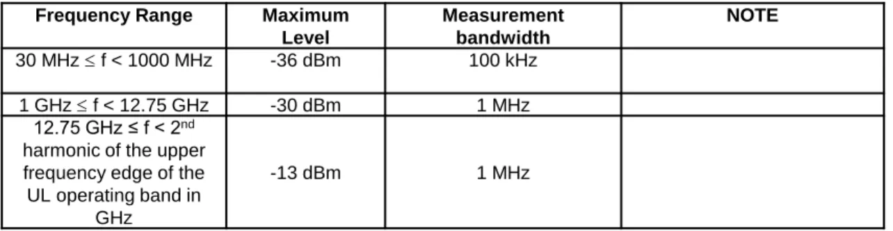
6.5.3
Spurious emissions
Frequency Range Maximum Level Measurement bandwidth NOTE 30 MHz ≤ f < 1000 MHz -36 dBm 100 kHz 1 GHz ≤ f < 12.75 GHz -30 dBm 1 MHz 12.75 GHz ≤ f < 2nd
harmonic of the upper frequency edge of the UL operating band in
GHz
-13 dBm 1 MHz
Table 6.5.3.1-2: Spurious emissions limits
20
TS38.521-02 as of April 2018 (After RAN5 NR#2 AdHoc)
6.5.3.1 Transmitter Spurious emissions
Editor’s Note : Following aspects are missing or under discussion
- Details of the coarse-scan (step 5-a) and max EIRP measurement (step 5-b) is TBD. Depending on the outcome of the study on step 5-a, 5-b, they could be removed.
-Testability issue for 30M1GHz ~ [12.75GHz] is identified. How to treat this frequency range is TBD. - Dynamic measurement bandwidth is missing as optional method in the test procedure.
測定項目
(1)送信装置 – イ) スプリアス領域における
不要発射の強度
TS38.521-02 as of April 2018
6.5.3.1 Test requirement (Transmitter Spurious emissions)
21
Frequency Range Maximum Level Measurement Bandwidth Notes 30 MHz ≤ f < 1000 MHz -36 dBm 100 kHz 1 GHz ≤ f < 12.75 GHz -30 dBm 1 MHz 12.75 GHz ≤ f < 2ndharmonic of
the upper frequency edge of the UL operating band in GHz
-13 dBm 1 MHz Note 1
NOTE 1: Applies for Band n257, n258, n260
Table 6.5.3.1.5-1: General spurious emissions test requirements
参考:
日本国内での対象バンドはn257 (26.5GHz – 29.5GHz)RAN4/5で議論されている技術的課題
・
1GHz未満の周波数帯を測定するにあたって必要とされる電波暗室の寸法問題。
- 4月のRAN5会合で30MHz ~ 1GHzを試験実施しないこと合意。
・周波数帯に応じ、複数の測定アンテナが必要
・
TRP測定に伴う測定時間の長時間化
規格化予定
暫定値について検討中
3GPPにおける確定値は2019年5月に完成予定
測定項目
(1)送信装置 – ウ) 隣接チャネル漏えい電力
TS38.521-02 as of April 2018 (After RAN5 NR#2 AdHoc)
6.5.2.3 Adjacent Channel Leakage Ratio
Adjacent Channel Leakage power Ratio (ACLR) is the ratio of the filtered mean power centred on the assigned channel frequency to the filtered mean power centred on an adjacent channel frequency. ACLR requirement is specified for a scenario in which adjacent carrier is another NR channel.
Editor’s note: This clause is incomplete. The following aspects are either missing or not yet determined:
Measurement Uncertainties and Test Tolerances are FFS. Reference Measurement Channel for UL is TBD.
Minimum conformance requirements for UE maximum output power for modulation/ channel bandwidth test are missing.
Test procedure is valid for following permitted RF testing methodologies: Direct Far Field, Direct Far Field simplification for centre of beam measurements, Indirect Far Field method 1. How to define Test
procedure for different RF testing methodologies is TBD. The applicability of specific RF testing methodologies with UE Category is FFS.
The procedure to ensure UE is at maximum output power is TBD.
測定項目
(1)送信装置 – ウ) 隣接チャネル漏えい電力
TS38.521-02 as of April 2018
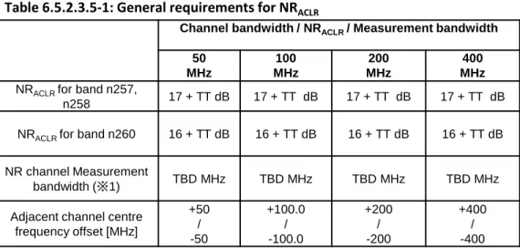
6.5.2.3.5 Test requirement (ACLR)
Channel bandwidth / NRACLR / Measurement bandwidth 50 MHz 100 MHz 200 MHz 400 MHz
NRACLR for band n257,
n258 17 + TT dB 17 + TT dB 17 + TT dB 17 + TT dB NRACLR for band n260 16 + TT dB 16 + TT dB 16 + TT dB 16 + TT dB
NR channel Measurement
bandwidth (※1) TBD MHz TBD MHz TBD MHz TBD MHz Adjacent channel centre
frequency offset [MHz] +50 / -50 +100.0 / -100.0 +200 / -200 +400 / -400
Table 6.5.2.3.5-1: General requirements for NRACLR
23
RAN4/5で議論されている技術的課題
・
TRP測定に伴う測定時間の長時間化
規格化予定
暫定値について検討中
3GPPにおける確定値は2019年5月に完成予定
※1: MBWはRAN4側で規定済みで、RAN5側反映が残測定項目
(1)送信装置 – エ) スペクトラムマスク
TS38.521-02 as of April 2018 (After RAN5 NR#2 AdHoc)
6.5.2.1 Spectrum emission mask
The spectrum emission mask of the UE applies to frequencies (Δfoob) starting from the ± edge of the assigned NR channel bandwidth. For frequencies greater than (Δfoob) the spurious requirements in subclause 6.5.3 are applicable.
Editor’s note: This clause is incomplete. The following aspects are either missing or not yet determined:
• Measurement Uncertainties and Test Tolerancies are FFS.
• Reference Measurement Channel for UL is TBD.
• Minimum conformance requirements for UE maximum output power for modulation/ channel bandwidth
test are missing.
• Test procedure is valid for following permitted RF testing methodologies: Direct Far Field, Direct Far Field
simplification for centre of beam measurements, Indirect Far Field method 1. How to define Test procedure for different RF testing methodologies is TBD. The applicability of specific RF testing methodologies with UE Category is FFS.
• The procedure to ensure UE is at maximum output power is TBD.
• Optimization in test frequencies is FFS.
測定項目
(1)送信装置 – エ) スペクトラムマスク
TS38.521-02 as of April 2018
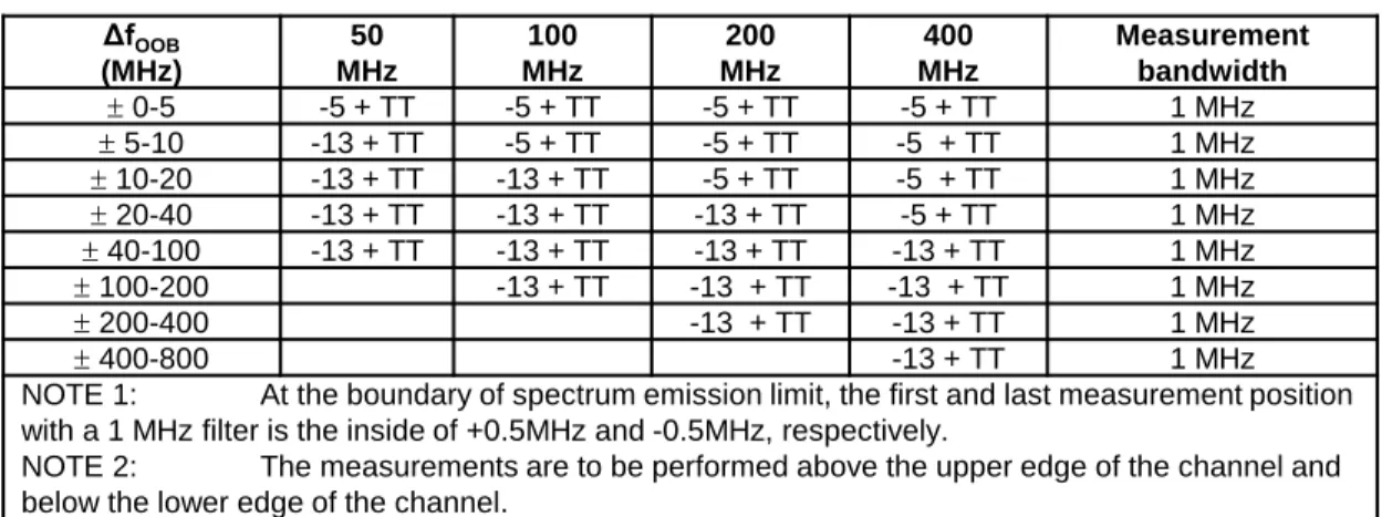
6.5.2.1.5 Test requirement (SEM)
The power of any UE emission shall not exceed the levels specified in Table 6.5.2.1.3-1 for the specified channel bandwidth. ΔfOOB (MHz) 50 MHz 100 MHz 200 MHz 400 MHz Measurement bandwidth ± 0-5 -5 + TT -5 + TT -5 + TT -5 + TT 1 MHz ± 5-10 -13 + TT -5 + TT -5 + TT -5 + TT 1 MHz ± 10-20 -13 + TT -13 + TT -5 + TT -5 + TT 1 MHz ± 20-40 -13 + TT -13 + TT -13 + TT -5 + TT 1 MHz ± 40-100 -13 + TT -13 + TT -13 + TT -13 + TT 1 MHz ± 100-200 -13 + TT -13 + TT -13 + TT 1 MHz ± 200-400 -13 + TT -13 + TT 1 MHz ± 400-800 -13 + TT 1 MHz
NOTE 1: At the boundary of spectrum emission limit, the first and last measurement position with a 1 MHz filter is the inside of +0.5MHz and -0.5MHz, respectively.
NOTE 2: The measurements are to be performed above the upper edge of the channel and below the lower edge of the channel.
Table 6.5.2.1.3-1: General NR spectrum emission mask for Range 2.
25
RAN4/5で議論されている技術的課題
・
TRP測定に伴う測定時間の長時間化
規格化予定
暫定値について検討中
3GPPにおける確定値は2019年5月に完成予定
測定項目
(1)送信装置 – オ) 占有周波数帯幅
TS38.521-02 as of April 2018 (After RAN5 NR#2 AdHoc)
6.5.1
Occupied bandwidth
Editor’s note: This clause is incomplete. The following aspects are either missing or not yet determined:
• Measurement Uncertainty FFS. • Test Tolerances are FFS.
• Reference Measurement Channel for UL is TBD.
• Test procedure is valid for following permitted RF testing methodologies: Direct Far Field, Direct Far Field simplification for centre of beam measurements, Indirect Far Field method 1. How to define Test procedure for different RF testing methodologies is TBD.
• How to define Test procedure for different UE categories is FFS.
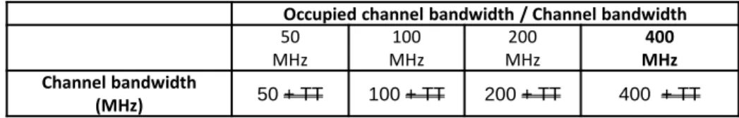
6.5.1.5 Test requirement (Occupied bandwidth)
The measured Occupied Bandwidth shall not exceed values in Table 6.5.1.5-1.
26 Table 6.5.1.5-1: Occupied channel bandwidth
Occupied channel bandwidth / Channel bandwidth
50 MHz MHz100 MHz200 MHz400 Channel bandwidth (MHz) 50 + TT 100 + TT 200 + TT 400 + TT
RAN4/5で議論されている技術的課題
・
TRP測定に伴う測定時間の長時間化
規格化予定
暫定値について検討中
3GPPにおける確定値は2019年5月に完成予定
測定項目
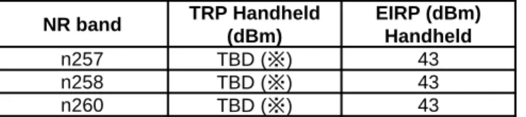
(1)送信装置 – カ) 空中線電力(TRP)
TS38.101-02 as of April 2018
6.2.1
UE maximum output power
The following UE Power Classes define the maximum output power radiated by the UE for any transmission bandwidth within the channel bandwidth for non-CA configuration, unless otherwise stated. The period of measurement shall be at least one sub frame (1ms). The values listed on the table below are for handheld UE, defined as minimum peak EIRP.
Table 6.2.1-1: NR FR2 UE Power Class
27
NR band Handheld Power Class Min Peak EIRP (dBm)
n257 [21.2-25.2] n258 [21.2.25.2] n260 [19.4-23.7] NOTE 1: minimum peak EIRP is defined as the
lower limit without tolerance
The maximum output power values for TRP and EIRP are found on the table below. The max allowed EIRP is derived from regulatory requirements
Table 6.2.1-2: NR UE Maximum Output Power Limits
NR band TRP Handheld (dBm) EIRP (dBm) Handheld n257 TBD (※) 43 n258 TBD (※) 43 n260 TBD (※) 43 ※R4-1801193にて+23dBmで合意されており、事実上定義済み。 規格への反映漏れ状態。
測定項目
(1)送信装置 – カ) 空中線電力(TRP)
TS38.521-02 as of April 2018
6.2
Transmit power
未定義RAN4/5で議論されている技術的課題
- TRP測定時の測定ポイント数検討
- 測定方向の定義 (Maximum EIRPが得られる測定方向の決定方法と、許容される誤差)
- 測定時間
補足情報
5G の技術的条件ではUEによる最低限の送受信範囲を表す指標として、Spherical coverageとい
う規格が定義される予定。
(2018年5月規格化予定)
規格化予定
暫定値について検討中
3GPPにおける確定値は2019年1月に完成予定
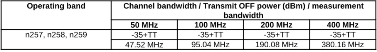
28測定項目
(1)送信装置 – キ) 送信オフ時電力)
TS38.521-02 as of April 2018
6.3.2
Transmit OFF power
Editor's note: This test case is not complete. Following aspects are either missing or not yet
determined:
- The test tolerance is left FFS. - The requirement is unmeasurable.
- Test applicability and test description are left FFS.
6.3.2.5 Test requirement (Transmit off power)
The requirement for the transmit OFF power shall not exceed the values specified in Table 6.3.2.5-1.
29
Operating band Channel bandwidth / Transmit OFF power (dBm) / measurement bandwidth
50 MHz 100 MHz 200 MHz 400 MHz
n257, n258, n259 -35+TT -35+TT -35+TT -35+TT 47.52 MHz 95.04 MHz 190.08 MHz 380.16 MHz
RAN4/5で議論されている技術的課題
- 現状規定されている信号レベルが測定器の検知下限以下 (Ref. R4-1709858)
Best case DUT Power off = 10dB + 10dB – 88dBm + 59.1dB – 17dB + 2dB = – 23.9dBm (400MHz) Worst case DUT Power off = 10dB + 16dB – 88dBm + 59.1dB – 15dB + 4dB = – 13.9dBm
上記の問題を鑑み、技術的条件においては下記の様な条件を記載する必要があると思われる。
「測定系の環境上、以下の許容値を測定することが困難な場合には、測定限界値をその条件
での許容値とする」
規格化予定
暫定値について検討中
3GPPにおける確定値は2019年5月に完成予定
30測定項目
(1)送信装置 – キ) 送信オフ時電力)
測定項目
(2)受信装置 – ア) 受信感度(EIS)
TS38.101-02 as of April 2018
7.3.2
Reference sensitivity power level
The reference sensitivity power level REFSENS is the EIS level (total component) at the centre of the quiet zone in the RX beam peak direction, at which the throughput shall meet or exceed the requirements for the
specified reference measurement channel.
The throughput shall be ≥ 95% of the maximum throughput of the reference measurement channels as specified in [Annex A] (with one sided dynamic OCNG Pattern OP.1 FDD/TDD for the DL-signal) with peak reference sensitivity specified in Table 7.3-1.
31
Operating band REFSENS (dBm) / Channel bandwidth
50 MHz 100 MHz 200 MHz 400 MHz
n257 [-92.1 to -85.4 ] [-89.1 to -82.4 ] [-83.1 to -76.4 ] n258 [-92.1 to -85.4 ] [-89.1 to -82.4 ] [-83.1 to -76.4 ] n260 [-91.8 to -82.6 ] [-88.8 to -79.6 ] [-82.8 to -73.6 ]
Table 7.3.2-1: Reference sensitivity
TS38.521-02 as of April 2018
7.3.2
Reference sensitivity power level
未定義
RAN4/5で議論されている技術的課題
Peak Gain Directionの決め方に伴う測定グリッド間隔。
規格化予定
暫定値について検討中
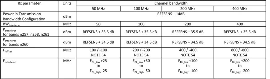
測定項目
(2)受信装置 – イ) ブロッキング(インバンドのみ)
TS38.101-02 as of April 2018
7.6.1
In-band blocking
7.6.1.1 Minimum requirements
In-band blocking is defined for an unwanted interfering signal falling into the UE receive band or into the
spectrum equivalent to twice the channel bandwidth below or above the UE receive band at which the relative throughput shall meet or exceed the minimum requirement for the specified measurement channels.
The throughput shall be ≥ 95% of the maximum throughput of the reference measurement channels as specified in Annexes A.X.X (with one sided dynamic OCNG Pattern for the DL-signal as described in Annex A.X.X.X) with parameters specified in Tables 7.6.2-1.
32 Table 7.6.2-1: In band blocking requirements
Rx parameter Units Channel bandwidth
50 MHz 100 MHz 200 MHz 400 MHz
Power in Transmission
Bandwidth Configuration dBm REFSENS + 14dB
BWInterferer MHz 50 100 200 400
PInterferer
for bands n257, n258, n261 dBm REFSENS + 35.5 dB REFSENS + 35.5 dB REFSENS + 35.5 dB REFSENS + 35.5 dB PInterferer
for bands n260 dBm REFSENS + 34.5 dB REFSENS + 34.5 dB REFSENS + 34.5 dB REFSENS + 34.5 dB FIoffset MHz 100 / -100
NOTE 54 200 / -200NOTE 54 400 / -400NOTE 54 800 / -800NOTE 54 FInterferer MHz FDL_low+25 to FDL_high-25 FDL_low+50 to FDL_high-50 FDL_low+100 to FDL_high-100 FDL_low+200 to FDL_high-200
NOTE 1: The interferer consists of the Reference measurement channel specified in Annex A.X.X with one sided dynamic OCNG Pattern as described in Annex A.X.X.X and set-up according to Annex C.X.X.
NOTE2: The REFSENS power level is specified in Table 7.X.X.X.
NOTE 3: The wanted signal consists of the reference measurement channel specified in Annex A.X.X (QPSK, R=X/X) with one sided dynamic OCNG pattern as described in Annex A.X.X.X and set-up according to Annex C.X.X
NOTE 4: FIoffsetis the frequency separation between the center of the aggregated CA bandwidth and the center frequency of the Interferer signal.
NOTE 5: The absolute value of the interferer offset FIoffsetshall be further adjusted to
MHz with SCS the sub-carrier spacing of the wanted signal in MHz. Wanted and interferer signal have same SCS. NOTE 6: FInterfererrange values for unwanted modulated interfering signals are interferer center frequencies.
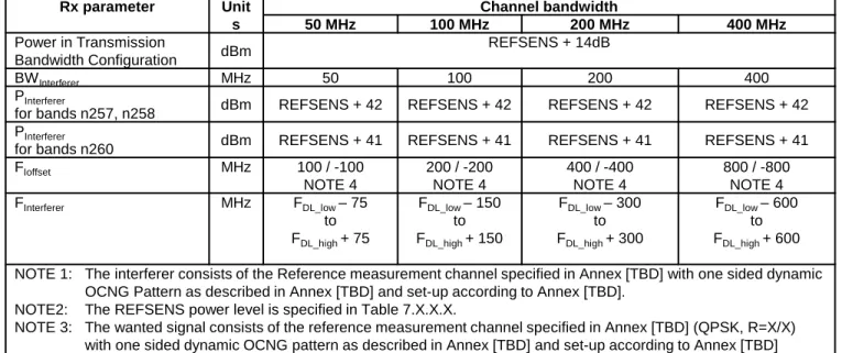
測定項目
(2)受信装置 – イ) ブロッキング(インバンドのみ)
TS38.521-02 as of April 2018(After RAN5 NR#2 AdHoc)
7.6.1
In-band blocking
Editor’s note: This clause is incomplete. The following aspects are either missing or not yet determined:
• Measurement uncertainty and test tolerances are FFS.
• Reference Measurement Channels for UL and DL are TBD.
• OCNG Pattern OP.1 TDD is TBD.
• UL power level configuration is TBD.
• Throughput calculation procedure is TBD (measurement period as well as depedencies with polarizations).
• Test procedure is valid for following permitted RF testing methodologies: Direct Far Field, Direct Far Field
simplification for centre of beam measurements, Indirect Far Field method 1. How to define Test procedure for different RF testing methodologies is TBD.
• The applicability of specific RF testing methodologies with UE Category is FFS.
測定項目
(2)受信装置 – イ) ブロッキング(インバンドのみ)
34 Rx parameter Unit s Channel bandwidth 50 MHz 100 MHz 200 MHz 400 MHz Power in Transmission Bandwidth Configuration dBm REFSENS + 14dB BWInterferer MHz 50 100 200 400 PInterfererfor bands n257, n258 dBm REFSENS + 42 REFSENS + 42 REFSENS + 42 REFSENS + 42 PInterferer
for bands n260 dBm REFSENS + 41 REFSENS + 41 REFSENS + 41 REFSENS + 41 FIoffset MHz 100 / -100 NOTE 4 200 / -200 NOTE 4 400 / -400 NOTE 4 800 / -800 NOTE 4 FInterferer MHz FDL_low– 75 to FDL_high+ 75 FDL_low– 150 to FDL_high+ 150 FDL_low– 300 to FDL_high+ 300 FDL_low– 600 to FDL_high+ 600 NOTE 1: The interferer consists of the Reference measurement channel specified in Annex [TBD] with one sided dynamic
OCNG Pattern as described in Annex [TBD] and set-up according to Annex [TBD]. NOTE2: The REFSENS power level is specified in Table 7.X.X.X.
NOTE 3: The wanted signal consists of the reference measurement channel specified in Annex [TBD] (QPSK, R=X/X) with one sided dynamic OCNG pattern as described in Annex [TBD] and set-up according to Annex [TBD] NOTE 4: The absolute value of the interferer offset FInterferer (offset) shall be further adjusted to
MHz with SCS the sub-carrier spacing of the wanted signal in MHz. Wanted and interferer signal have same SCS.
Table 7.6.1.5-1: In band blocking test requirement
RAN4 #86bis会合(4月)の変更点の反映が未
RAN4/5で議論されている技術的課題
- 測定距離に応じて、空間伝送損失の影響によりブロッカーの送信信号レベルが確保できない
可能性有。
規格化予定
暫定値について検討中
3GPPにおける確定値は2019年5月に完成予定
測定項目
(2)受信装置 – ウ) 隣接チャネル選択度
TS38.101-02 as of April 2018
7.5
Adjacent Channel Selectivity
Adjacent Channel Selectivity (ACS) is a measure of a receiver's ability to receive a NR signal at its assigned channel frequency in the presence of an adjacent channel signal at a given frequency offset from the centre frequency of the assigned channel. ACS is the ratio of the receive filter attenuation on the assigned channel frequency to the receive filter attenuation on the adjacent channel(s).
The requirement applies at the RIB when the AoA of the incident wave of the wanted signal and the interfering signal are both from the direction where peak gain is achieved.
The wanted and interfering signals apply to all supported polarizations, under the assumption of polarization match.
The UE shall fulfil the minimum requirement specified in Table 7.5-1 for all values of an adjacent channel interferer up to –25 dBm. However it is not possible to directly measure the ACS, instead the lower and upper range of test parameters are chosen in Table 7.5-2 and Table 7.5-3 where the throughput shall be ≥ 95% of the maximum throughput of the reference measurement channels as specified in Annexes A.X.X, A.X.X and A.X.X (with QPSK, R=X/X and one sided dynamic OCNG Pattern OP.1 TDD for the DL-signal as described in Annex A.X.X.X). For operating bands with an unpaired DL part (as noted in Table 5.5-1), the requirements only apply for carriers assigned in the paired part.
35 Channel bandwidth Rx Parameter Units 50 MHz 100 MHz 200 MHz 400 MHz
ACS for band
n257, n258 dB 23 23 23 23
ACS for band
n260 dB 22 22 22 22
測定項目
(2)受信装置 – ウ) 隣接チャネル選択度
36
Rx Parameter Units Channel bandwidth
50 MHz 100 MHz 200 MHz 400 MHz
Power in Transmission Bandwidth Configuration
dBm
REFSENS + 14 dB PInterferer for band n257,
n258 dBm REFSENS + 35.5 dB REFSENS +35.5dB REFSENS +35.5dB REFSENS +35.5dB PInterferer for band n260
dBm REFSENS + 34.5 dB REFSENS +34.5dB REFSENS +34.5dB REFSENS +34.5dB BWInterferer MHz 50 100 200 400 FInterferer(offset) MHz 50 / -50 NOTE 3 100 / -100 NOTE 3 200 / -200 NOTE 3 400 / -400 NOTE 3 NOTE 1: The interferer consists of the Reference measurement channel specified in Annex A.X.X with one sided dynamic OCNG Pattern as described in
Annex A.X.X.X and set-up according to Annex C.3.1. NOTE 2: The REFSENS power level is specified in Table [XXXXXX].
NOTE 3: The absolute value of the interferer offset FInterferer(offset) shall be further adjusted to MHz with SCS the sub-carrier spacing of the wanted signal in
MHz. Wanted and interferer signal have same SCS.
Table 7.5-2: Test parameters for adjacent channel selectivity, Case 1
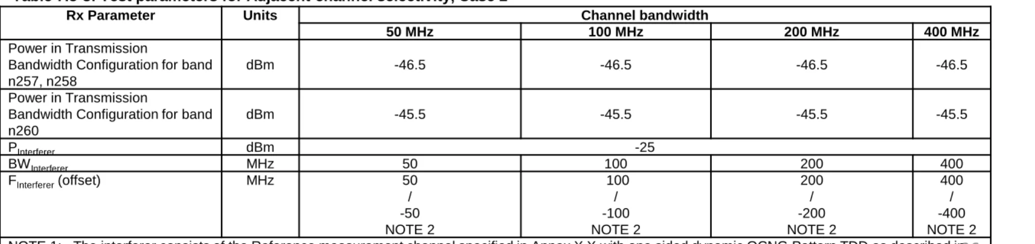
Rx Parameter Units Channel bandwidth
50 MHz 100 MHz 200 MHz 400 MHz
Power in Transmission
Bandwidth Configuration for band n257, n258
dBm -46.5 -46.5 -46.5 -46.5
Power in Transmission
Bandwidth Configuration for band n260 dBm -45.5 -45.5 -45.5 -45.5 PInterferer dBm -25 BWInterferer MHz 50 100 200 400 FInterferer(offset) MHz 50 / -50 NOTE 2 100 / -100 NOTE 2 200 / -200 NOTE 2 400 / -400 NOTE 2 NOTE 1: The interferer consists of the Reference measurement channel specified in Annex X.X with one sided dynamic OCNG Pattern TDD as described in
Annex A.X.X.X and set-up according to Annex C.X.X.
NOTE 2: The absolute value of the interferer offset FInterferer (offset) shall be further adjusted to MHz with SCS the sub-carrier spacing of the wanted signal in MHz. Wanted and interferer signal have same SCS.
測定項目
(2)受信装置 – ウ) 隣接チャネル選択度
37
TS38.521-02 as of April 2018 (After RAN5 NR#2 AdHoc)
7.5
Adjacent Channel Selectivity
Editor’s note: This clause is incomplete. The following aspects are either missing or not yet determined:
- Measurement Uncertainty and Test Tolerances are FFS.
- Reference Measurement Channels for UL and DL are TBD.
- OCNG Pattern OP.1 TDD is TBD.
- UL power level configuration is TBD.
- Throughput calculation procedure is TBD (measurement period as well as dependencies with
polarizations).
- Test procedure is valid for following permitted RF testing methodologies: Direct Far Field, Direct
Far Field simplification for centre of beam measurements, Indirect Far Field method 1. How to define Test procedure for different RF testing methodologies is TBD.
- How to define Test procedure for different UE categories is FFS.
RAN4/5で議論されている技術的課題
- Far Field距離に応じて、ブロッカーの送信信号レベルが確保できない可能性有。(ACS Case 2)
規格化予定
暫定値について検討中
測定項目
(2)受信装置 –オ) 副次的に発する電波等の限度
TS38.101-02 as of April 2018
7.9
Spurious emissions
The spurious emissions power is the power of emissions generated or amplified in a receiver. The spurious emissions power level is measured as TRP.
The power of any narrow band CW spurious emission shall not exceed the maximum level specified in Table 7.9-1.
Frequency band Measurement bandwidth Maximum level NOTE 30MHz ≤ f < 1GHz [100 kHz] [-57 dBm] 1 1GHz ≤ f ≤ 2ndharmonic of
the upper frequency edge of the DL operating band in
GHz
[1 MHz] [-47 dBm]
NOTE 1: Unused PDCCH resources are padded with resource element groups with power level given by PDCCH_RA/RB as defined in [Annex C.3.1].
Table 7.9.1-1: General receiver spurious emission requirements
38
TS38.521-02 as of April 2018
7.9
Spurious emissions
測定項目
(2)受信装置 –オ) 副次的に発する電波等の限度
RAN4/5で議論されている技術的課題
・
1GHz未満の周波数帯を測定するにあたって必要とされる電波暗室の寸法問題。
RAN5 NR#2 AdHoc会合にて30MHz ~ 6GHzを試験不要とすることが合意された。
・周波数帯に応じ、複数の測定アンテナが必要
・
TRP測定に伴う測定時間の長時間化
上記の問題を鑑み、技術的条件においては下記の様な条件を記載する必要があると思われる。
「測定系の環境上、以下の許容値を測定することが困難な場合には、測定限界値をその条件
での許容値とする」
規格化予定
暫定値について検討中
3GPPにおける確定値は2019年5月に完成予定
39その他:
Extreme condition (Temperature)
+ 25 °C ± [10] °C For normal (room temperature) conditions with relative humidity of 25% to 75%
-10 °C to +55 °C For extreme conditions
Table E.2.1-1: Temperature conditions
40
TS38.101-02 as of April 2018
E.2 Environmental
TS38.521-02 as of April 2018
E.2 Environmental
未定義
RAN4/5で議論されている技術的課題
・
Temperature condition – チャンバー内のQuiet zoneへ影響を与えずに温度調整する構造につ
いては検討が必要。
(現実的な実現性、対象規格を含め)
規格化予定
RAN5 NR#2 AdHocで決めたMU算出パラメータ一覧にはExtreme Conditionは記載されず、具体
的な完了時期は未定である。ただし、明確に優先度を下げる、ということは合意されていない。
•
Proposed Time plan
–
Target of the 1
stpriority : [MU] RAN5#NR3 (Oct-18) [TT] RAN5#XX (Jan-19)
–
Target of the 2
ndpriority : [MU] RAN5#82 (Feb-19) [TT] RAN5#83 (May-19)
–
Target of the 3
rdpriority : [MU] RAN5#83 (May-19) [TT] RAN5#84 (Aug-19)
–
Detailed estimation of the work can be re-defined during the RAN5#79 based on the
progress of 1
stpriority.
RAN5
Meeting Dates 1st Priority (12) 2nd Priority (32) 3rd Priority (44)
MU TT MU TT MU TT #NR2 Apr-18 #79 May-18 #80 Aug-18 #NR3 Oct-18 #81 Nov-18 #XX Jan-19 #82 Feb-19 #83 May-19 #84 Aug-19