Study on Residual Stress and Mechanical Behavior of
intermetallic Compound Layer in Diffusion Bonding
of Mg/Al Alloy
Yunlong Ding
CONTENTS
Chapter 1 Introduction...1
1.1 Background and development on bonding technology of magnesium alloy and aluminum alloy...1
1.2 Purpose of this research... 11
References...13
Chapter 2Effect of annealing temperature on microstructure and mechanical properties of the combined Mg/Al alloy... 19
2.1 Introduction...19
2.1.1 Heat treatment methods of magnesium alloys...20
2.1.2 Heat treatment methods of aluminium alloys...23
2.2 Diffusion equation... 25
2.2.1 Diffusion analysis by finite element method...26
2.3 Calculation method of Mg/Al volume ratio in the intermetallic compounds.... 28
2.4 Experiment on diffusion bonding of Mg/Al alloy... 29
2.5 Annealing process on diffusion bonded Mg/Al alloy...30
2.6 Evaluation on microstructure of the diffusion layers... 31
2.6.1 Investigation on microstructure with the applicaton of SEM...31
2.6.2 Analysis of element distribution based on EPMA... 33
2.6.3 Analysis and identification of crystal structure by XRD... 40
2.6.4 Study on crystal structure with the usage of TEM... 43
2.7 Evaluation on mechanical behaviors of diffusion bonded composite material..48
2.7.1 Evaluation methods of residual stress...48
2.7.2 Evaluation of residual stress in the bonding layer...54
2.7.3 Measurement of Vickers hardness... 56
2.7.4 Measurement of tensile strength...60
Concluding remarks...63
References...64
Chapter 3 Simulations based on heat conduction theory and constitutive equation of thermal-elastoplasticity... 68
3.1 Introduction...68
3.2 Thermal conduction analysis... 70
3.3 Constitutive equation of thermal-elastoplasticity... 71
3.5 Heat conduction analysis by finite element method...73
3.6 Analysis of thermo-elastoplasticity by finite element method...75
3.7 Calculation on thermo-elastoplastic performance parameters of intermetallic compounds based on the mixture law... 76
3.8 Simulations on diffusion bonding and annealing... 78
3.8.1 Selection of coupling field and element type...78
3.8.2 Setting of simulation conditions for diffusion bonding and annealing treatment...79
3.8.3 Results and discussion of simulations...80
Concluding remarks...86
References...88
Chapter 4 Effect of prior rolling on microstructure and property of diffusion bonded Mg/Al alloy...91
4.1 Introduction...91
4.2 Experiment on twin roll casting of Mg alloy...94
4.3 Rolling process on Mg alloy...96
4.4 Diffusion bonding and annealing process of rolled Mg alloy and Al alloy... 97
4.5 Evaluation of microstructure and mechanical property...98
4.5.1 Investigation of microstructure based on SEM... 98
4.5.2 Analysis of element distribution with the usage of EPMA... 101
4.5.3 Measurement of tensile strength...104
Concluding remarks...107
References...108
Chapter 5 Conclusions and recommendation...111
5.1 Conclusions...111
5.2 Recommendation... 114
Related publications...115
Chapter 1 Introduction
1.1 Background and development on bonding technology of
magnesium alloy and aluminum alloy
In recent years, with the rapid development of the transportation, aerospace and, national defense and military industry, and the economic development demand for energy, the expectation of lightweight structure of transportation machinery such as automobile and aviation is getting higher and higher. As the lightest metal [1], magnesium alloys have received more and more attentions because of the low density, high specific strength, excellent castability, outstanding vibration or shock energy absorption function. As the use of magnesium alloys, the weight of components can be reduced [2]. But it’s formability in cold working is poor, tearing and cracking always occur. What’s more, magnesium alloy can be corroded easily. However, aluminum alloys have attractive mechanical and metallurgical properties, good moldability and excellent corrosion resistance [3,4,5,6]. It is well known that aluminum alloys are also widely used in aerospace, automotive, machinery, electrical and chemical industry [7,8,9]. If aluminum alloy can be bonded with magnesium alloy and form a kind of composite material, not only would the flexibility and availability be improved substantially, but also the weight and cost would be reduced obviously. Therefore, the combination of superior functions of magnesium alloy and aluminum alloy becomes one direction of the research on lightweight of vehicle structure.
efficiently, benefiting from the specific properties of each material in a functional way. Welding is one of the most widely used methods for welding process of metals. Therefore, despite there are many difficulties, efforts have also been made to apply these methods to join dissimilar metals. These difficulties include issues related to metallurgical incompatibility, the formation of brittle phases, the separation of high and low melting phases due to chemical mismatch, and large residual stresses that may be caused by physical mismatch [11].
Fusion welding technology includes many welding techniques, such as commonly used conventional metal shielded arc, tungsten gas protection arc, gas metal arc and submerged arc welding. They also include processes characterized by high energy density, such as plasma arc, electron beam and laser beam welding. In addition to fusion welding, several other types of joining techniques can be used and are often associated with the difficulty of producing dissimilar metal joints. These methods include pressure welding, friction welding, resistance welding and diffusion welding, as well as brazing and welding, bonding and mechanical joining. Most of these techniques can eliminate the problem of fusion because base metals remain solid during the bonding process. Therefore, they are better than fusion in this regard. However, the conditions of usage may make a particular process unsuitable, and welding and bonding can not be candidates for high temperature applications, whereas mechanical connections are not acceptable for leak proof connections. In addition, the required joint geometry may make friction welding difficult to be applied. Diffusion welding often provides superior technical advantages for bonding small, dissimilar metal parts, but this process is quite time-consuming.
The electron beam welding
power supply system, vacuum pump system and control system. The simplified diagram of the EBW process is shown in Fig.1.1.
Fig.1.1 Simplified diagram of the EBW process
beam can be focused under the condition of vacuum and strikes the metal surface to be welded. About 95% of the electron kinetic energy is converted to heat. Typical voltage and current are respectively 30-175kV and 50-1000mA. The minimum weld width is about 0.8mm, and the obtained power density is as high as 1010 wm-2 [15].
One of EBW's main features is the ability to use the "keyhole" mechanism for deep penetration welding. Therefore,The EB weldments can achieve a high depth-to-width ratio. This characteristic not only can realize single-pass welding of thick plates, but also can perform the welding of relatively thin plates with a high travel speed. The advantages of EBW are shown as follows [16]:
1. The total amount of needed heat is low, so the thermal influence area is not easy to grow once more, and the workpieces are less deformed.
2. The high depth-width ratio can be obtained when welding task is carried out with small hole welding.
3. Single-beam electron beam welding can be used for welding up to 4 inches of material.
4. High purity welding environment (vacuum) can reduce the pollution of oxygen and nitrogen to metals.
5. A high vacuum or medium vacuum welding method can be used to weld closed containers that require internal vacuum maintenance.
6. The electron beam can use magnetic deflection to produce various shapes or use magnetic oscillations to improve welding quality or increase penetration.
7. Focusing the electron beam has a considerable depth of field, can be applied to a range of distances ranging from welding.
8. A fully welded, single-pass weld with approximately parallel sides and approximately symmetrical shrinkage can be obtained.
9. Dissimilar metals and materials with high thermal conductivity, can be welded. such as magnesium alloy and aluminium alloy, copper.
3. The workpieces usually must be clamped tightly.
4. Rapid cooling will cause cracks in the heat affected area, make the material brittle and leave pores in the weld.
5. The cost of quipment is expensive.
6. For vacuum and medium vacuum welding, the vacuum chamber should be large enough to accommodate the entire assembly. The time required to evacuate the vacuum chamber will affect the cost of the product.
7. Because the electron beam can be deflected by the magnetic field, so the device used for fixation on the electron beam path should be non-magnetic material or the correctly demagnetized metal material.
8. All EBWs must have radiological protection to ensure that no one is exposed to x-rays produced by electron beam welding.
9. For non-vacuum EBW, the advisable ventilation is required to ensure that ozone and other harmful gases produced during the EBW welding process are discharged.
Laser welding process
Laser welding process is a kind of welding technology with high power density [17,18]. Laser welding process offers great potential for the design of new products. Compared with other welding processes, less heat is added to the workpieces, which results in a smaller heat affected zone and lower panel deformation. In addition, it is advanced for it’s high productivity, high weld quality, low distortion, manufacturing flexibility, and facility for automation [19,20,21]. Therefore, it has become an important industrial process because of its advantages as a welding process over the other widely used joining techniques.
Fig.1.2 Simplified diagram of the LW process
The laser welding input parameters determine the shape of the laser welding bead 'keyhole' [23], because of the combination of these parameters control the heat input. In order to obtain good welding quality, the combination of output power, welding speed, focus position, shielding gas and position accuracy should be selected correctly [24]. The Response Surface Method is widely used to predict the geometry and mechanical properties of weld bead in many welding processes [25-29]. In the process of laser welding, the temperature dependence of the phase change of material properties, laser absorption and plasma reflection are very complex phenomena occurring in a very short time. The traditional experiment and error approaches based on welding experiment have encountered many difficulties in optimizing laser welding. In order to extend the industrial application of laser welding and make the process more reliable, numerical simulation of welding process has been used as the basis for optimizing welding parameters, which can control the welding process properly [30].
Explosive welding
process. Explosive welding is a special type of welding method, which is based on the high energy produced by the explosion [31,32], and it is well known for its capability, which can directly join a large variety of both similar and dissimilar combinations of metals that can not be completed by any other techniques [33-36]. Furthermore, Due to its ability to distribute high energy density through explosion, this process can join with high surface area [37–40]. Explosive welding is a solid-state welding process that can control explosive detonations to force two or more metals together at high pressure and high velocity oblique impact. The explosive charge when detonated accelerates the plates to a speed at which a metallic bond can be formed between the metal components during the collision. The metal plates collide with each other at high speed by using explosives. In the high-speed oblique collision of the metal plate, if the impact angle β and the impact velocity Vp are in the required range for bonding, a high-speed jet stream can be formed between the metal plates [41,42]. The simplified diagram of the explosive welding process is shown in Fig.1.3 (a) and (b).
Fig.1.3 (b) Simplified diagram of the explosive welding process
The oxide film is harmful to the establishment of metallurgical welding. The oxide film is blown off the interface by jet. Then the metal plate is sprayed with a spray to remove any surface film. At the point of collision, the original clean surface is gathered together under very high pressure. The pressure must be high enough and for a sufficient length of time to achieve inter-atomic bonding. The velocity Vc of the collision point can be used for controlling the bonding time. The high pressure also results in considerable local plastic deformation of the metal in the bonding area [43,44]. This kind of welding is metallurgy in nature, and usually is stronger than the weaker material.
The quality of welding area depends greatly on the careful control of process parameters. The parameters include material surface preparation, plate separation or departure distance, explosive load or explosive ratio, detonation energy and detonation velocity Vd. The selection of parameters is based on the mechanical
research has reported that the collision velocity Vc and the plate velocity Vp should be smaller than the sound velocity in any part to be welded [50,51]. The velocity of sound in engineering materials is typically 4.5–6 km/s, while the detonation velocity in common explosive (plastic explosive) is typically 6–7 km/s. The high speed explosives are not available for explosive welding [52,53]. In this reason, a mixture of ammonium nitrate and fuel oil and an inert substance such as sand or perlite is always used with the condition of detonation velocity typically between 2 and 3 km/s. The required explosive must also provide uniform detonation so that a collision velocity that will be uniform from the start to end of the weld can be obtained. The type and amount of explosions in unit area are selected to achieve the necessary detonation energy and detonation velocity. The wave interface is the characteristic of explosive welding. Wave formation in explosive welding can be regarded as a special case of normal phenomena of inter facial wave formation in a certain flow environment. The formation of waveform appears to be the result of velocity distribution variety and periodic disturbance of material. The cladding of plate and concentric cylinder constitutes the main commercial application of explosive welding. The advantages of the explosive package include: The joining of dissimilar metals; The bonding of thin sheet with thick plate; Weld the metals that are after heat treatment and cold worked together without changing their mechanical properties; the absence of heat affected zone in the clad plates and the simplicity and speed of operation for achieving welding with cost reduction and strength or corrosion properties [54].
Diffusion bonding
induced by applying heat and pressure for a finite interval [58]. So with the usage of diffusion bonding technology these defects produced during fusion welding could be avoided, and improve the structure stability and mechanical properties [59]. At present, diffusion bonding technology has been applied in the welding of dissimilar materials. Such as Ti/Al, Fe3Al/18-8 steel and Al/18-8 steel [60-62]. And it is most commonly used to weld "sandwiches" of alternating layers of thin metal foil, and metal wires or filaments [63]. Currently, the diffusion bonding method is widely used in the joining of high-strength and refractory metals within the aerospace and nuclear industries.
The advantages and applicability of the diffusion bonding process are as follows: diffusion bonding does not involve fluid fusion, and usually does not contain filler metals. The total weight does not increase, and the bonding layer tends to show the strength and heat resistance of the base metal at the same time. The material will not bear or bear small plastic deformation. The introduced residual stresses were very few and there was no contamination from the welding process. It can be performed theoretically on an arbitrary connection surface without increasing processing time; In fact, the surface is often limited by the required pressure and physical constraints. It can be carried out with similar and dissimilar metals, active and refractory metals, or pieces of different thicknesses.
Because of its relatively high cost, diffusion bonding is most often used for workpieces that are difficult or impossible to weld in other ways. Examples include welding materials, which are usually impossible to fuse with liquid. Such as zirconium and beryllium; Extremely high melting materials such as tungsten; The alternating layers of different metals must be maintained at high temperatures; And very thin honeycomb foil structure [64-67].
The advantages:
1. The welding layer has the same physical and mechanical properties as the basic material.
no discontinuity and porosity. In other words, the welded workpiece can be processed and heat treated.
3. Diffusion welding can build high-precision parts with complex shapes. Moreover, diffusion is flexible.
4. Diffusion bonding can be widely used and can be used to join similar or dissimilar materials and can be used for the processing of composite materials. 5. This process is not very difficult to approach, and the cost of implementing
diffusion bonding is not very high.
6. The plastic deformation of materials welded by diffusion bonding method can be reduced .
Applicability:
Diffusion bonding is mainly used to create complex forms for electronics, aerospace and nuclear industries. Compared with other connection technology (such as explosion welding), need quite a long time because of the connection, so the quantity of components is small, and are mostly automatic manufactured. However, due to different requirements, some of the time interval could be accomplished in few minutes. In an attempt to reduce fastener count, labor costs, and quantities of parts, diffusion bonding, in conjunction with super-plastic forming, is also used when creating complex forms of metal sheets. Multiple sheets are stacked atop one another and bonded in specific sections. The stack is then piled into a mold and gas pressure makes the sheets to fill the mold. This is often accomplished with the usage of titanium or aluminum alloys for parts needed in the aerospace industry. Typical materials that are welded include titanium, beryllium, and zirconium. In many military aircraft, diffusion bonding will help save expensive strategic materials and reduce manufacturing costs. For some aircraft, the quantities of diffusion bonding components have exceeded 100, these includes fuselages, outboard and inboard actuator fittings, landing gear trunnions, and nacelle frames.
1.2 Purpose of this research
has so many advantages. However, although diffusion bonding process was applied, the intermetallic compounds of Mg and Al, such as Al3Mg2 and Al12Mg17will form in
References
[1] Zhao L.M., Zhang Z.D., Effect of Zn alloy interlayer on interface microstructures and strength of diffusion-bonded Mg-Al joints [J]. Scripta Materialia. 58 (2008) pp.283-286.
[2] L. Commin a, M. Dumont, J.-E. Masse, L. Barrallier, Friction stir welding of AZ31 magnesium alloy rolled sheets: Influence of processing parameters[J]. Acta Materialia. 57 (2009) pp.326–334.
[3] SHE Qing-yuan, YAN Hong-ge, CHEN Ji-hua, SU Bin, YU Zhao-hui, CHEN Chao, XIA Wei-jun, Microstructure characteristics and liquation behavior of fiber laser welded joints of Mg−5Zn−1Mn−0.6Sn alloy sheets [J]. Transactins of Nonferrous Metals Society of China. 57 (2017) pp.812−819.
[4] Liu L. M., Liu F., Effect of Ce on microstructures and properties of Mg/Al butt joint welded by gas tungsten arc with Zn–30Al–xCe filler metal [J]. Science and Technology of Welding and Joining. 18 (2013) pp.414-420.
[5] Liu Liming, Liu Fei, Zhu Meili, Study on Mg/Al weld seam based on Zn-Mg-Al ternary alloy [J]. Materials. 7 (2014) pp.1173-1187.
[6] Yan Y.B., Zhang Z.W., Shen W., Wang J.H., Zhang L.K., Chin B.A., Microstructures and properties of magnesium AZ31B-aluminum 7075 explosively welded composite plate [J]. Materials Science and engineering A. 527 (2010) pp.2241-2245.
[7] Li Xianrong, Liang Wei, Zhao Xingguo, Zhang Yan, Fu Xiaopeng, Liu Fencheng, Bonding of Mg and Al with Mg-Al eutectic alloy and its application in aluminum coating on magnesium [J]. Journal of Alloys and Compounds. 471 (2009) pp.408-411.
[8] Liu Fei, Ren Daxin, Liu Liming, Effect of Al foils interlayer on microstructures and mechanical properties of Mg-Al butt joints welded by gas tungsten arc welding filling with Zn filler metal [J]. Materials and Design. 46 (2013) pp.419-425.
and fracture of magnesium-aluminum laminated composite plates fabricated by direct hot pressing[J]. Materials Science and Engineering A. 528 (2011) pp.6584-6588.
[10]Li Ma, Dingyong He, Xiaoyan Li and Jianmin Jiang, Microstructures and mechanical properties of magnesium alloy AZ31B brazed Joint using a Zn-Mg-Al filler metal[J]. J. Mater. Sci. Technol. 26 (2010) pp.743-746.
[11]Z. Sun R. Karppi b, The application of electron beam welding for the joining of dissimilar metals: an overview. Journal of Materials Processing Technology. 59 (1996) pp.257 -267.
[12]Qi Yunlian , Deng Ju, Hong Quan, Zeng Liying, Electron beam welding, laser beam welding and gas tungsten arc welding of titanium sheet. Materials Science and Engineering. A280 (2000) pp.177–181.
[13]Kutsuna, M., Yan, Q.U, Study on porosity formation in laser welds of aluminum alloys (Report 2)—mechanism of porosity formation by hydrogen magnesium. J. Light Met. Weld. Constr. 36 (11) (1998) pp.1–17.
[14]Ion, J.C, Laser beam welding of wrought aluminum alloys. Sci. Technol. Weld. Joining. 5 (5) (2000) pp.265–276.
[15]Crafer, R. C, Improved welding performance from a 2 kW axial flow CO2 laser welding machine. Advances in welding processes. Fourth international conference. Cambridge, England: The Welding Institute. (1978) p.267.
[16]Electron beam welding.http://www.maihanji.com/baike/showbk _2201.Html. [17]K.Y.Benyounis, A.G.OlabiM, S.J.Hashmi, Effect of laser welding parameters on
the heat input and weld-bead profile. Journal of Materials Processing Technology. 164–165 (2005) pp.978-985.
[18]C. Dharmendra, K.P. Rao, J. Wilden, S. Reich, Study on laser welding–brazing of zinc coated steel to aluminum alloy with a zinc based filler. Materials Science and Engineering A. 528 (2011) pp.1497–1503.
(2003) pp.23–49.
[20]Kutsuna, M., Yan, Q.U, Study on porosity formation in laser welds of aluminum alloys (Report 2)—mechanism of porosity formation by hydrogen magnesium. J. Light Met. Weld. Constr. 36 (11) (1998) pp.1–17.
[21]Ion, J.C. Laser beam welding of wrought aluminum alloys. Sci. Technol. Weld. Joining. 5 (5) (2000) pp.265–276.
[22]W. M. Steen, Laser Material processing, Springer, London. (1991). [23]C. Dawes, Laser welding. Abington Publishing, New York. NY (1992).
[24]Q. Huang, J. Hagstroem, H. Skoog and G. Kullberg, Effect of laser parameter variation on sheet metal welding. Inter. J. for the Joining of Materials. 3/3 (1991) pp.79-88.
[25]D. Kim et al, Modelling and optimisation of a GMA welding process by genetic algorithm and response surface methodology, INT. Journal of PROD. RES. 40/7 (2002) pp.1699-1711.
[26]V. Gunaraj and N. Murugan, Application of response surface methodology for predicting weld bead quality in SAW of pipes, Journal of Mater. Processing Technology. 88 (1999) pp.266-275.
[27]K.Y. Benyounis, A. H. Bettamer, A.G. Olabi and M.S.J. Hashmi, Predicting the impact strength of spiral-welded pipe joints in SAW of low carbon steel. Proceedings of IMC21, Limerick Ireland. Sep. (2004).
[28]V. Gunaraj and N. Murugan, Prediction of Heat- Affected Zone Characteristics in SAW of Structural Steel Pipes. Welding Journal, American Welding Society. Jan. (2002) pp.94-98.
[29]T.T. Allen, R.W. Richardson, D.P. Tagliable and G.P. Maul, Statistical process Design for Robotic GMA Welding of Sheet Metal. Welding Journal, American Welding Society. May (2002) pp.69-77.
welding parameters and their effects on microhardness and shear strength. Materials and Design. 24 (2003) pp.659–664.
[32]Ahmet Durgutlu, Behcet Gulenc, Fehim Findik, Examination of copper/stainless steel joints formed by explosive welding. Materials and Design. 26 (2005) pp.497–507.
[33]Fehim Findik, Recent developments in explosive welding, Review. Materials and Design. 32 (2011) pp.1081–1093.
[34]A.G. Mamalis, A. Szalay, N.M. Vaxevanidis, D.I. Pantelis, Macroscopic and microscopik phenomena of nickel/titanium “Shapememory” bimetalic strips fabricated by explosive cladding and rolling, Mater. Sci. Eng. A. 188 (1994) pp.267–275.
[35]A. Abe, Numerical study of the mechanism of wavy interface generation in explosive welding, JSME Int. J. 40 (3) (1997) pp.395–401.
[36]V. Balasubramanian, M. Rathinasabapathi, K. Raghukandan, Modelling of process parameters in explosive cladding of mildsteel and aluminium, J. Mater. Process. Technol. 63 (1997) pp.83–88.
[37]A.G. Mamalis, A. Szalay, N.M. Vaxevanidis, D.I. Pantelis, Macroscopic and microscopik phenomena of nickel/titanium “Shapememory” bimetalic strips fabricated by explosive cladding and rolling, Mater. Sci. Eng. A. 188 (1994) pp.267–275.
[38]A. Abe, Numerical study of the mechanism of wavy interface generation in explosive welding, JSME Int. J. 40(3) (1997) pp.395–401.
[39]V. Balasubramanian, M. Rathinasabapathi, K. Raghukandan, Modelling of process parameters in explosive cladding of mildsteel and aluminium, J. Mater. Process. Technol. 63 (1997) pp.83–88.
[40]Nizamettin Kahraman, Behcet Gulenc, Microstructural and mechanical
7properties of Cu–Ti plates bonded through explosive welding process. Journal of Materials Processing Technology. 169 (2005) pp.67–71.
[42]Rughue N, Characterization of explosive weld interface. In: Proc intern sympres stud mat sci eng, Chennai, India. December (2004).
[43]Akbari Mousavi SAA, Al-Hassani STS, Numerical and experimental studies of mechanism of wavy interface formations in explosive/impact welding. J Mech Phys Sol. 12 (2005) pp.251–279.
[44]Akbari Mousavi SAA, Al-Hassani STS, Burley SJ, Simulation of explosive welding using the Williamsburg equation of state to model low detonation velocity explosives. Int J Imp Eng. 31 (2005) pp.719–734.
[45] Crossland B, Williams JD, Explosive welding. Met Rev. 15 (1970) pp.79–100. [46] Loyer A, Talerman M, Hay DR, Explosive welding: the weldability window for
dissimilar metals and alloys. In: Third int symp use exp ene manuf metallic mat new prop. (1976) p.43.
[47]Wittman RH, Use of explosive energy in manufacturing metallic materials of new properties. In: Second int symp, Marianski, Lazne, Czechoslovakia. (1973). [48]SW, Wittman RH, Computer selection of the optimum explosive loading and
welding geometry. In: Proc fifth int conf high ener rate fab. 4(2) (1975) pp.1–16. [49]AA, Simonov VA, Zakcharenko ID, Investigations on explosive welding
parameters for arbitrary combinations of metals and alloys. In: Proc sixth int conf high ener rate fab. 4(1) (1975) p.1024.
[50]Bahrani AS, Crossland B, Explosive welding and cladding: an introductory survey and preliminary results. Proc Inst Mech Eng. 79 (1964) p.264.
[51]Birkhoff G, MacDougall DP, Pugh EM, Taylor G, Explosive with lined cavities. J Appl Phys. 19 (1948) pp.563–582.
[52]Abrahamson GR, Permanent periodic surface deformations due to a traveling jet. J Appl Mech. 83 (1961) pp.519–528.
[53]Wylie HK, Williams PEG, Crossland B, Further experimental investigation of explosive welding parameters. In: Proc second int conf cen high ener fab. 1(3) (1971) pp.1–43.
[55]O. Torun, A. Karabulut, B. Baksan, I. Celikyurek, Diffusion bonding of AZ31 using a silver interlayer. Materials and Design. 29 (2008) pp.2043–2046.
[56]Ren Jiangwei, Li Yajiang, Feng Tao, Microstructure characteristics in the interface zone of Ti/Al diffusion bonding. Materials Letters. 56 (2002) pp.647– 652.
[57]C.S. Lee, H. Li, R.S. Chandel, Vacuum-free diffusion bonding of aluminium metal matrix composite. Journal of Materials Processing Technology. 89-90 (1999) pp.326-330.
[58]W.A. Owczarski, D.F. Paulonis, Application of diffusion welding in the USA. Welding Journal. 60 (2) (1981) pp.22– 33.
[59]Liu Penga, Li Yajianga, Geng Haoranb, Wang Juan, Investigation of interfacial structure of Mg/Al vacuum diffusion-bonded joint. Vacuum. 80 (2006) pp.395–399.
[60]Ren JW, Li YJ, Feng T, Microstructure characteristics in the interface zone of Ti/Al diffusion bonding. Mater Lett. 56 (5) (2002) pp.647–652.
[61]Li YJ, Wang J, Mater Sci Technol. 12 (1) (2004) pp.45–48.
[62]Liu P, Li YJ, Wang J, Guo JS, Vcuum brazing technology and microstructure near the interface of Al/18-8 stainless steel. Mater Res Bull. 38 (9–10) (2003) pp.1493–1499.
[63]VanDyke Kevin, Streeter Gigi, Dreher Jon, Leyrer Larry, Diffusion bonding. (2012). retrieved 2016-02-17
[64]Schrader George F, Elshennway Ahmad K, Manufacturing Processes and Materials (4th illustrated ed.). ISBN 0872635171. pp.319–320.
[65]Chawla Krishan K, Composite Materials: Science and Engineering. Materials research and engineering (2nd illustrated ed.). ISBN 0387984097. p.174.
[66]Jacobson David M, Giles Humpston, Principles of Brazing. 1st ed. Ohio: ASM International. USA. (2005) pp.11–14.
Chapter 2 Effect
of
annealing
temperature
on
microstructure and mechanical properties of the combined
Mg/Al alloy
2.1 Introduction
Heat treatment is a group of industrial and metalworking processes used to alter the physical, and sometimes chemical, properties of a material. The most common application is metallurgical. Heat treatment is a a comprehensive process, in which metal or alloy in solid state is heated to a certain temperature in a certain medium, and maintained at this temperature for a certain period of time, then cool down at a certain rate.
Heat treatment generally does not change the shape and the overall chemical composition of the workpiece, But make the component obtain special mechanical behaviors or improve the usage performance of the workpiece by changing the internal microstructure, or change the chemical composition of the surface.
The characteristic of heat treatment is to improve the inherent quality of the workpiece, however, the transform of the inherent quality is generally not visible to the naked eye. Generally speaking, heat treatment process is made up by three procedures, which are heating, holding and cooling. Sometimes it only contains heating and cooling processes. These processes are interconnected and can’t be interrupted. Throughout the production process of metals or alloys, the appropriate heat treatment could be applied to improve the performance of metal materials.
a workpiece; if it’s used as a final operation, it can make the metals and alloys meet the required mechanical, physical, and chemical properties, in addition, it can ensure the products meet the specified quality requirements.
In the aspect of affecting the depth and diversity of structural changes of metals, heat treatment is more effective than machining and other treatments. Heat treatment can also be combined with chemical treatment, deformation processing and magnetic field effect, to improve the performance of metal materials further more.
In order to make the metal components obtain the required mechanical properties, physical properties and chemical properties. In addition to the rational choice of materials and a variety of forming processes, the heat treatment process is often essential. For example, steel is the most widely used material in the machinery industry. Its complex microstructure can be controlled by heat treatment to obtain the required mechanical properties and physicochemical properties.
In addition, aluminum, copper, magnesium, titanium and its alloys can also be treated to change their mechanical, physical and chemical properties, in order to obtain different usability. Such as aluminum generally need to be strengthened to improve the strength, in order to achieve the required mechanical properties. Conventional heat treatment process of magnesium alloy is divided into two categories, which are annealing and solution aging treatment.
2.1.1 Heat treatment methods of magnesium alloys
Annealing can significantly reduce the hardness of magnesium alloy products, and at the same time, increase their plasticity, which is beneficial for some subsequent processing. Depending on the application requirements and the properties of the alloy, for the deformed magnesium alloy, high temperature full annealing (o) and low temperature stress relief annealing (T2) can be applied.
The purpose of annealing:
3. To improve the microstructure for the preparation of quenching. 4. Eliminate internal stress.
Fully annealing can eliminate the work-hardening effect of magnesium alloy during plastic deformation, further more, restore and enhance its plasticity and make it easy for the subsequent deformation processing. During fully annealing, recrystallization and grain growth will occur, so the temperature can not be too high, and the annealing time can neither be too long. If the magnesium alloy contains rare earth elements, its recrystallization temperature will increase. The microstructures of AM60, AZ61, AZ60, AZ31 magnesium alloy treated by hot rolling or hot extrusion annealing can be improved. Stress relief annealing can reduce or eliminate the residual stress generated in the deformed magnesium alloy products during hot and cold processing, forming, correcting and welding. And the residual stress in castings or ingots can also be eliminated [1].
1. Solution treatment
For obtaining aging enhancement, the premise is a supersaturated solid solution. First heating to the appropriate temperature, which belongs to the single phase solid solution phase zone, and holding for appropriate time so that the alloy elements in the original microstructure dissolved in the matrix metal completely to form a supersaturated solid solution. The process above is called solution heat treatment. According to the Hmue - Rothery rule, If the difference between the radius of the atoms of solvent and solute exceeds 14%~15%, the solid solubility of this solvent in this kind of solute will not be very great. The radius of Mg atom is 3.2nm. So the solid solubility of the elements, such as Li, Al, Ti, Cr, Zn, Ge, Yt, Zr, Nb, Mo, Pd, Ti, Pb, Bi will be obviously. In addition, if the negative charge of a given element has a great difference with that of Mg, for example, when the difference of Gordy's negative charge is more than 0.4, it is impossible to have a significant solid solubility. That is because Mg and the element tend to form stable compounds rather than solid solutions.
reinforcement(especially room temperature strength), in alloys, when the solid solubility of the alloy elements decreases as the temperature decreases, then aging enhancement may be produced. The alloy with this feature is solutionized at high temperature to obtain an unstable supersaturated solid solution, then carry out aging treatment at a lower temperature to produce a dispersion precipitation phase. The sliding dislocation interacts with the precipitation phase to make the yield strength increase and the magnesium alloy is strengthened:
ayield aGb L T
T 2 / (2-1)
Where Tyield is the yield strength of the precipitated alloy; Ta is the yield strength of
the precipitated matrix ; (2aGb/L) is the stress required to bend the dislocations between precipitates.
Due to the high diffusion activation energy, the vast majority of magnesium alloys are not sensitive to the natural aging, after quenching process, the quenched state can be maintained at room temperature for a long time. A part of the magnesium alloy, after forming by casting or processing, are without solid solution treatment, but directly treated by artificial aging. This process is very simple, the stress of the workpiece can be eliminated, and its tensile strength can also be increased slightly. For the Mg-Zn series alloys, when the thermal deformation processes are completed, they are often directly treated by the artificial aging process to obtain the aging enhancement effect, then the products at T5 state can be obtained.
3. Solution treatment plus artificial aging
elements. The situation is very complicated. In addition, for the different series of magnesium alloy, the heat treatment process is different; for the different types of workpieces, heat treatment process is not the same.
For the extrusion components of magnesium alloy, after demoulding process, forced air cooling or water cooling is used for quenching, aiming at obtaining fine and uniform microstructure. However, in the quenching process, the directly contacting between the cooling water and hot mold is forbidden, otherwise it will lead to mold cracking.
The main states of extruded magnesium alloys are T5, T6 and F. T5 is the state that the artificial aging is applied after quenching process on-line; T6 is the state of solution treatment and artificial aging; F is the original processing state that is the squeezing state. Solution treatment can increase the strength, make the toughness maximize , and improve the shock resistance. The process, combining the solution treatment and the artificial aging, can achieve the maximum hardness and strength, but toughness will decrease a little. Magnesium alloys will contain residual stresses after hot working, forming, straightening and welding. Therefore, stress relief annealing should be performed.
2.1.2 Heat treatment methods of aluminium alloys
1. AnnealingThe product is heated to a certain temperature and holding for a certain time, then cooling at a certain cooling rate to room temperature.
processes, is a kind of heat treatment method, which is under a lower temperature and hold for a short time aiming at improving the plasticity of the material and eliminating the processing stress in the material, what’s more, benefiting the continuous process or obtain some properties,
(3) Fully annealing, also known as finished product annealing, is to hold for a certain time at a high temperature, in order to obtain soften microstructure under fully recrystallized state, the microstructure possesses the best plasticity and lower strength. 2. Solution quenching
The heat-treatable aluminum alloy material is heated to a higher temperature and hold for a certain period of time to make the second phase or other soluble components in the material fully dissolve into the aluminum matrix to form a supersaturated solid solution. Then the supersaturated solid solution is cooled to room temperature by fast cooling method, it’s an unstable state, because of the state of high energy, the solute atoms will precipitate at any time. But the plasticity is very well so that it can be cold processed or used for straightening process.
(1) Online quenching
For some alloys, whose quenching sensitivity are not high, can be taken for the solid solution process with the high temperature during squeezing, and then air-cooled (T5) or water-cooled (T6) for quenching to obtain a certain microstructure and performance.
(2) Offline quenching
For some quenching sensitive alloy materials, they must be reheated to a higher temperature in a special heat treatment furnace and hold for a certain period of time, then transferred into the water or oil in 15 seconds for quenching to obtain a certain microstructure and performance. According to the difference of equipment, offline quenching can be divided into these categories, such as: salt bath quenching, air quenching, vertical quenching, horizontal quenching.
precipitate from the supersaturated solid solution (or precipitate), then distribute around the α (AL) aluminum grains, and result in strengthening effect, this effect is called precipitation (precipitation) strengthen.
(1) Natural aging: Some alloys (such as 2024, etc.) can produce precipitation strengthening effect at room temperature, which is called natural aging effect.
(2) Artificial aging: Some alloys (such as 7075, etc.) can not produce precipitation strengthen at room temperature obviously, but it is obvious at higher temperatures, which is known as artificial aging.
Artificial aging can be divided into under-aging and over-aging.
① Under- aging: In order to obtain a certain performance, control the lower aging temperature and hold for a shorter aging time.
② Over-aging: In order to obtain some special properties and better comprehensive performance, the aging process is carried out at a higher temperature or a longer holding time.
③ Multi-stage aging: In order to obtain some special properties and good comprehensive performance, the aging process is divided into several stages.
Such as two stages aging and three stages aging.
4. Regression treatment: In order to improve the plasticity, easy to cold forming or correct the geometric tolerance. For the products, which have been treated for quenching aging, when they are at high temperature and heated for a short time, they can reinstate to the state just after quenching. This phenomenon is called regression.
2.2 Diffusion equation
For the diffusion bonding process of magnesium alloy sheet and aluminium alloy sheet, the diffusion of element Mg and element Al between magnesium alloy sheet and aluminium alloy sheet have to be taken account. Diffusion phenomenon can be analyzed by Fick’s law, which is shown in equation (2-2):
2 2 C D C t x (2-2)
element,which represents the diffusion property of element [4]. In addition, generally speaking, the diffusion coefficient D is a function of element concentration,and the function is expressed as equation (2-3):
0exp( 1 )
D K K C (2-3)
WhereK0,K1 are coefficient. Generally,if the variety of microstructure is ignored,
The diffusion equation for element concentration C is displayed as equation (2-4):
( )
C div DgradCg (2-4)
The boundary condition used for diffusion analysis is displayed as equation (2-5):
( )
c c w
D gradC C C
gn (2-5)
Where is the diffusion coefficient of surrounding gas etc, andc Cw is the
concentration of the surrounding element.
2.2.1 Diffusion analysis by finite element method
The diffusion equation is represented by equation (2-3) and (2-4). For diffusion analysis in coupled analyzes, as a boundary condition, the boundary penetration of elements on the surface of the continuum may be taken into consideration. The extent of element penetration at such boundaries is given in the form of the boundary penetration rate of the element defined as below.
s e s
q D C C (2-6)
Where q is the amount of element entering from the interface, Dsis the boundary
penetration rate of element, Ce is element concentration in external environment, and
Csis the element concentration on the surface of the object.
For the formulation of the diffusion analysis by the finite element method, the region V is first divided into a finite number of elements [5]. The element concentration C at any time t within each element is assumed as the product of the shape function
N
eC N C (2-7)
By using the principle of the weighted residual method, the residual errors of the element concentration approximated by the above equation and the true solution become zero in average for the concentration distribution of the chemical components in the region, so the element concentration at the node can be obtained by the following integral equation. That is to say, the weight function and the residual error are orthogonalized by the following equation.
0h
i i c w
VW C div DgradC dV s W gradC C C C ds
g
gn (2-8)Where the Galerkin method is applied to the above equation, That is to say, a shape function Ni is used as the weight function Wi. If the element concentration at the
node is expressed as C jj
1 n
, then the equation as follows can be obtained.
1 0 h h N i j i c j j i j i V s V j i C w s D C gradN gradN dV N C N dV C N N dV C N C C ds
g g (2-9)When this formula is rewritten in matrix form, it becomes a simplified form as follows:
H Cc
P Cc
g
Qc 0 (2-10)Where the matrix and vector are represented as follows:
e c c H
H ,
Pc
Pc e,
e c c Q
Q (2-11)As the above, the diffusion equation for the entire region was obtained.The diffusion coefficient D included in this equation is dependent on the element concentration. Therefore, the matrix
Hc ,
Pc , and
Qc become the functions of element concentration.Therefore, using the difference approximation method, equation (2-10) can be applied as follows. At first, Assuming that the change of element concentration C from time
obtained.
t t t t C C C t g (2-12)So the equation (2-12) can be represented as follows:
c
c
c t t t c P P H C C Q t t (2-13)Where
C represents the vector of element concentration at time t. If the matrix
Hc ,
Pc , and
Qc approximately do not change from time t t to t, theresults at time t t are
Hc t t ,
Pc t t , and
Qc t t . So the equation (2-13) can be rewritten as follows:
c t t
c t t
c t t t t t c t t P P H C C Q t t (2-14)Therefore, if
C ,
Hc ,
Pc , and
Qc at the previous time step are alreadyknown, it is possible to obtain
C at the subsequent stage from the above equation.2.3 Calculation method of Mg/Al volume ratio in the
intermetallic compounds
Definition:there are a substance which is constituted by element Mg and Al. The volume is V0, and the unit is liter (L).
Atomic weight, volume, weight, mass, and relative atomic mass are represented by C, V, G, m and Ar. Avogadro's constant, atomic number, amount of substance and molar
concentration are represented by NA, M, n and CB. When 1 is attached to each symbol,
it indicates each unit of Mg, in the conditon of attaching 2, it indicates each unit of Al. For example, the atomic weight of Al is C1, the atomic weight of Al is C2.
The atomic number ratio of Mg and Al is expressed by the following equation.
The molar concentration of Mg is written as the following equation. A B VMN C 0 1 1 (2-16)
The unit is mol/L.
The amount of substance of Mg can be represented as equation (2-17)
g Ar G n 1 1 1 (2-17)
Where g is the gravitational acceleration. Because volume is the of amount of substance n and molar concentration CB,so the volume of Mg can be expressed as
equation (2-18). 1 1 1 B C n V (2-18)
When take the equation (2-16) and (2-17) into equation (2-18), then the volume of Mg can be represented as the following equation.
g C N V G V A 1 0 1 1 (2-19)
Similarly, the volume of Al can be expressed as the equation (2-20).
g C N V G V A 2 0 2 2 (2-20)
Therefore, the volume ratio of Mg and Al in this substance is represented as equation (2-21). 1 2 2 1 2 1 C G C G V V (2-21)
According to the quantitative analysis results of EDS, since the values of atomic weight C and weight G are known, so the ratio of the volume can be obtained.
2.4 Experiment on diffusion bonding of Mg/Al alloy
sheets according to the size 50mm*12mm*2mm. Then the oxide layers on the surface of substrate were polished by using abrasive papers #400, and the ground samples were wiped with acetone before joining. After that, the materials were put into the furnace, then closed the door of the furnace.
The next work is to turn on the switch of the pump for vacuum. When the degree of vacuum reached -0.1MPa, turned off the switch, and at the same time, open the embolus of the argon gas cylinder and the intake valve to insert argon gas into the furnace until the barometer pointer turned back to 0. Then opened the exhaust valve. The most important step is the set of temperatures and time for the diffusion joining process. According to the phase diagram (shown in Fig.2.1), the joining temperature was set at 440℃, and heating time is 10 minutes, holding time is 1 hour. After the temperature setting, turned on the power, the controller started to work, temperature increased gradually. After cooling down to room temperature in the furnace, specimens were successfully joined.
Fig.2.1 Phase diagram of magnesium alloy
2.5 Annealing process on diffusion bonded Mg/Al alloy
improve the mechanical properties of bonding layers, the samples were used for the annealing treatment experiments. At first, turn on the switch of the pump for vacuum. When the degree of vacuum reached -0.1MPa, turned off the switch of pump, and at the same time, open the embolus of argon gas cylinder and intake valve to insert argon gas into the furnace until the barometer pointer turned back to 0. Then opened the exhaust valve.
The second step is to set the annealing temperatures and time for annealing treatment process. According to the phase diagram (shown in Fig.2.1), According to the Mg-Al phase graph and annealing experience. The heat treatment temperatures were set as 200℃, 225℃, 250℃, 275℃ and 300℃, and the holding time was 60min, heating rate is 42℃/min, holding time is 1 hour. After the temperature setting, turned on the power, then the controller started to work, and temperature increased gradually. After cooling down to room temperature in the furnace, the annealing were completed.
2.6 Evaluation on microstructure of the diffusion layers
For the purpose of studying the effect of annealing temperatures on the microstructures and properties of interfaces, a series of specimens that were treated at different conditions were cut crossing diffusion zone. Then inlaid the component containing diffusion layers into resin for making the specimens to investigate the microstructures. The sections were ground by the grinder with abrasive papers (GRIT 240, 600, 800, 1200). And polished with polishing compound until the microstructure of diffusion zone can be observed clearly. The microstructures and element distribution of the joints were studied respectively by SEM and EPMA. At last, the crystal index was investigated and identified with the usage of X-ray diffraction (XRD).
observed. Firstly, the ground specimen inlaided in resin was set on the holder and put into the equipment for microstructure investigation. Secondly, waiting for a moment until the vacuum is ready. Then turn on the high voltage and increase the voltage from 1kv to 15 kv gradually. The third is to adjust the position of sample until it come into the visual area of the screen. The last step is to select the area which will be observed, and adjust the magnification, then scan the surface of sample and save the results. The specimens treated at different conditions were all observed.
The microstructures of joints annealed at 200℃, 225℃, 250℃, 275℃ and 300℃ are shown in Fig.2.2 (b), (c), (d), (e) and (f) respectively, While (a) shows the microstructures of joints without annealing treatment. It can be thought that the diffusion layers with heat treatment can be seen clearly including layer A, layer B, layer C shown in Fig.2.2 (a), (b), (c), (d), (e) and (f). What’s more, it can be known that the width of diffusion layers increases with the increasing annealing temperatures. That is because diffusion rate turns faster with the increasing temperatures.
(c) 225℃ (d) 250℃
(e) 275℃ (f) 300℃
Fig.2.2 The microstructure of the diffusion zone
2.6.2 Analysis of element distribution based on EPMA
The element analysis was carried out with the application of EPMA. Cooling water and protection gas need to be applied before the equipment was started. At first, the specimens were stuck with conductive tape respectively, and put into the different position of the holder. Secondly, the holder was put into the device called EPMA, then wait for about 30 minutes until the vacuum state is ready. The third step is to open the electronic optical system, add the high voltage and adjust the magnitude of the current to 10-9, then select the position of sample, and adjust the focus, contrast and
analysis of another specimen. At last, the specimens without annealing, annealed at 200℃, 225℃, 250℃, 275℃ and 300℃ were all analyzed.
After the data processing, the results of element analysis are shown in the Figs from Fig.2.3 to Fig.2.8. According to the results, it can be thought that the diffusion layers can be seen clearly. The different colors stand for the quantities of elements that were detected. The quantities increase with the change of colors from black to white. For example, as it is shown on the left side of Fig.2.6. it’s the analysis result of Mg element.
The pink zone is the side of magnesium alloy, the black zone is Al alloy. The blue and green zone is the diffusion layer near Al side, the area between pink zone and green zone is the diffusion layer near Mg side. The quantify of magnesium element decrease along the direction from Mg alloy to Al alloy, while the quantify of Al element changes contrary with Mg element in the same direction.
Fig.2.4 The result of surface scan for element analysis (annealing at 200℃)
Fig.2.5 The investigation on element distribution after annealing at 225℃
Fig.2.7 The element distribution in diffusion layers of specimen annealed at 275℃
Fig.2.8 The result of surface scan on element detection (annealing at 300℃)
(e)
(f)
Fig.2.9 Line scan of element distribution (a) without annealing (b) annealing at 200℃ (c) annealing temperature: 225℃ (d) the specimen annealed at 250℃ (e) under the annealing
condition of 275℃ (f) in the case of 300℃
Fig.2.8) that quantity of elements after annealed at 250℃ are steady. It indicates that the distribution of elements are relatively uniform. That is to say the microstructure is more uniform.
2.6.3 Analysis and identification of crystal structure by XRD
For the purpose of analyzing and identifying the crystal structure about crystal structure, the investigation of the diffusion bonded specimens with the usage of XRD was carried out. The results were shown in the following Figs. Fig.2.10 shows the investigating result of Mg side. The investigating results of the diffusion layers, such as the layer near Mg, the middle layer and the layer near Al were shown in Fig.2.11, Fig.2.12, and Fig.2.13 respectively. In addition, the investigating result of Al side was shown in Fig.2.14. It can be obtained from the results above that the diffraction peak of Mg occurred at the place of 2θ 67.3° and 72.5°. The peak of the diffusion layer
which was near Mg was at the place of 2θ 69.7°. The diffraction peaks of the middle
diffusion layer appeared at 2θ of 77.5°, 77.8°, and 77.9°. In the case of the diffusion
layer near Al, 2θ were 64.5° and 64.7° where the diffraction peaks appeared. In the
condition of Al. the locations of peaks were 37.9°, 44.2°and 81°.
Fig.2.11 The result on XRD of the diffusion layer near Mg side
Fig.2.13 The diffraction peak of the diffusion layer near Al side
Fig.2.14 The diffraction diagram on Al side of specimen
The results of identification of Al and Mg were shown in Fig.2.15 and 2.16. As the diffraction peaks of Al appeared when 2θ were 37.9°, 44.2°, and 81°, so it can be
Fig.2.15 The result on x-ray diffraction of Al
In the case of Mg, the diffraction peaks at the place where 2θ were 67°and 72.8°stood
for the planes whose plane indexes were (200) and (004).
Fig.2.16 The measurement result based on XRD for identification of Mg
2.6.4 Study on crystal structure with the usage of TEM
using the grinder with abrasive papers, in addition, the sample was processed to about 0.1µm by fine finishing with the application of Focussed Ion Beam Scanning Electron Microscopes (FIB-SEM). The result was shown in Fig.2.17.
Fig.2.17 The image of the sample after FIB process
It can be seen from Fig.2.17 that the width of the processed section decreased gradually with the increasing number of processes. Actually, the width was 20μm in the fist process, and 6μm in the last process.
Fig.2.18 The microstructure of workpiece for investigation
Fig.2.19 The diffraction pattern of specimen
According to the scale in Fig.2.19, and the measurement of the distance to the center, the actual interplanar spacing was calculated, after compared with the database, the
(1511)
(771)
A
conclusion was obtained that d1is 0.283nm, d2 is 0.187nm. The results indicated the
(771) and (1511) planes of Al3Mg2.
Fig.2.20 Microstructure of the specimen for crystal structure analysis
Fig.2.21 The diffraction image obtained from TEM observation
Based on the scale in Fig.2.21, and the distance to the center. The interplanar spacing can be calculated. Therefore, the plane index can be confirmed by referring to the database. The interplanar spacing d1, d2 ,d3 are respectively 0.2480nm, 0.2640nm,
0.1600nm. So the corresponding plane index are (330), (400), and (622) of Al12Mg17.
Fig.2.22 The micrograph of the sample for TEM experiment
(102) (101)
C
Fig.2.23 The diffraction spots for the analysis of crystal structure
For the analysis of Fig.2.23, according to the distance from the diffraction spots to the center and the scale of Fig.2.23, the interplanar spacing were calculated. After referring to the database, the planes index can be obtained. The interplanar spacing were d1=0.1902nm, d2=0.2452nm, and the corresponding planes index were (102) and
(101) of Mg.
2.7 Evaluation on mechanical behaviors of diffusion bonded
composite material
2.7.1 Evaluation methods of residual stress
Residual stresses are stresses that remain in a solid material after the original cause of the stresses has been removed. Residual stresses can also be defined as the stresses that remain within a material or body after manufacture and material processing in the absence of external forces or thermal gradients. They can also be produced by service loading, leading to inhomogeneous plastic deformation in the part or specimen [6]. Accordingly, residual stresses are not caused by loads (forces or moments). Residual stress may be desirable or undesirable. For example, laser peening imparts deep beneficial compressive residual stresses into metal components such as turbine engine fan blades, and it is used in toughened glass to allow for large, thin, crack- and scratch-resistant glass displays on smartphones. However, unintended residual stress in a designed structure may cause it to fail prematurely.
Residual stresses can occur through a variety of mechanisms including inelastic (plastic) deformations, temperature gradients or phase transformation. Heat from welding may cause localized expansion, which is taken up during welding by either the molten metal or the placement of parts being welded. When the finished weldment cools, some areas cool and contract more than others, leaving residual stresses. Another example occurs during semiconductor fabrication and
crystalline properties are deposited sequentially under different process conditions. The stress variation through a stack of thin film materials can be very complex and can vary between compressive and tensile stresses from layer to layer.
During the process of usage, residual stress will superimpose with the working stress caused by other loads, and result in secondary deformation and residual stress redistribution of component. Not only will the stiffness and stability of the structure be reduced, but also under the combined action of temperature and medium, it will seriously affect the structural fatigue strength, brittle fracture resistance, resistance to stress corrosion cracking and high temperature creep cracking [8,9].
The effect to stiffness of the structure:
When the stress δ resulted from external load superimposes with the residual stress in some place of the component, and reaches the yield point, The material in this area will have partial plastic deformation,so that the material will lost the ability to bear the further load,and the effective cross-sectional area of the structure will be reduced, the stiffness of the structure will also be reduced. When there are longitudinal and transverse welds in the component, or be treated for flame correction, It is possible to produce residual tensile stress on a larger cross-section. Although the stress distribution in the direction of length is not too large, but they still have a greater impact on the stiffness. For the structures that require higher dimensional accuracy and stability, the effect can not be ignored.
The impact on stability of rod parts:
When the compressive stress that is caused by external load superimposes with residual compressive stress, and reached yield point, this part of the section will lost the ability to withstand more external load. The effective cross-sectional area of the rod is reduced.Then the stiffness will decrease, and the stable bearing capacity will also decrease. So the influence of residual stress on the stable bearing capacity of bar is related to the distribution of residual stress.
deformation, and the residual stress in the cross-section will redistribute. When the external factors are removed, deformation will occur in the entire component. During the usage of components, the relaxation residual stress will occurs, so the residual stress affects the stability of the components. This is one of the most concerned issues for the engineering department.
The effect of residual stress on the deformation of component includes two aspects: the one is the ability of the component to resist the deformation resulted from static and dynamic load; the other is the ability to recover the deformation after unloading. The effect of residual stresses on the components in these two aspects is significant, so the effective ways to eliminate this effect is studied.
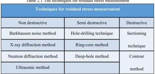
Table 2.1 The techniques for residual stress measurement Techniques for residual stress measurement
Non destructive Semi destructive Destructive
Barkhausen noise method Hole-drilling technique Sectioning technique X-ray diffraction method Ring-core method
Neutron diffraction method Deep-hole method Contour method Ultrasonic method
Hole-drilling technique
The hole-drilling method is simple; it is one of the most popularly used semi destructive methods for residual stress evaluation which can provide the measurement of residual stress distribution across the thickness in magnitude, direction and sense. The damage caused to the specimen is limited to the small, drilled hole, and is often tolerable or repairable [10]. Due to drilling the hole, residual stresses can be relieved and the corresponding strains on the surface can be measured [11]. Based on the strains measured around the hole, the residual stresses can be calculated using appropriate calibration constants [12].
The ring-core method
The ring-core method is an “inside-out” variant of the hole-drilling method [13]. The ring core method can measure stress based on measuring the deformation in a central area caused by the cutting of an annular slot in the surrounding material. Compared with the hole-drilling method, the ring-core method has a basic implementation to evaluate in-plane stresses [14,15]. The ring-core method has an advantage over the hole-drilling method that it provides much larger surface strains. However, the ring-core method is less frequently used for the reason of greater specimen damage and less convenient, .
Deep hole method
and ring-core methods [16,17]. A hole is first drilled through the workpiece. Then the diameter of the hole can be measured accurately and then a core of material around the hole is taken out, so that the residual stresses in the core is relaxed. Finally the residual stresses can be calculated from the change in diameter of the hole. The the residual stress will be calculated with appropriate calibration constants.
Sectioning technique
The Sectioning technique is a destructive method that relies on measuring the deformation due to the release of residual stress by removing material from the sample [18,19]. It has been widely used to analyze the residual stresses in structural carbon steel, aluminum and stainless steel sections [20-22]. This measurement method includes cutting on the instrumented panel to release residual stresses that is on the cutting line. For this reason, the applied cutting process should not introduce plasticity or heat, so that the original residual stress can be measured without the effect of plasticity on the surface of the cutting plane.
The strain released during the cutting process is generally measured. Usually, the material strips released through the slicing process can exhibit axial deformation and curvature corresponding to the residual stress of membrane and bending (penetrating thickness).
Contour method
The contour method is a new relaxation method for the measurement of residual stress, which makes a 2D residual stress map enable to be evaluated on the plane of interest [23]. Contour methods provide higher spatial resolution, while the sectioning technique is easier to use because it nearly requires no calculations [24-26]. The contour method is better than the traditional relaxation method of measuring residual stress. The theoretical basis of the contour method is a variation of Bueckners elastic superposition principle. [27-29].
X-ray diffraction method
atomic planes in the metallic crystal structure. X-ray diffraction can directly measure the interplanar atomic spacing. Then the total stress of the metal can be obtained [30-32]. Therefore, X-ray diffraction residual stress measurement is suitable for crystalline, relatively fine-grained materials, and diffraction can be produced on any orientation of the specimen’s surface.
Ultrasonic Methods
When material is under stress, the ultrasonic velocity changes can be observed, and these changes provide a measure of the average stress along the wave path. Calibration tests are usually used to calculate the acoustic elastic coefficients, which is required for analysis. Different types of waves can be used, but the commonly used technique is the critical refraction longitudinal wave method. The maximum sensitivity is obtained when the propagation direction of the wave is the same as that of the stress [33].
The basic equation for the stress calculation is shown as follows:
V =V0+ Kσ (2-22)
where V0is the velocity of a wave in an unstressed medium, σ is the stress and K is a
material parameter that is known as acoustoelastic constant [34].
Neutron Diffraction
The neutron diffraction method is very similar to the X-ray method because it depends on the elastic deformation in the polycrystalline material, which causes spacing change of the lattice plane from the stress-free state. Neutron diffraction is a nondestructive method to determine the residual stress of crystal materials [35].