A low overhead trace and compression system for Automotive RTOS
7
0
0
全文
(2) IPSJ SIG Technical Report. directly with human beings. A failure in these systems directly threaten the lives of human beings. What is important to note is that the more complex a system becomes, the more dependent the system becomes on the software within the system. This also means that software becomes the major factor that can trigger failures in such systems. A software tracer is one of the most effective ways to investigate and identify the causes of software failures. Within the automotive realm, AUTOSAR is the defacto standard for the enabling the introduction of more complex software into ECUs. AUTOSAR, however, does not currently specify a logging feature for OS-level events and we believe that a OS tracing system could benefit the AUTOSAR platform, particularly because automotive systems work with many independently constructed third party components. There are several issues in creating a OS tracer for AUTOSAR. First, automotive embedded systems are poor in resources. The commonly used microcontrollers have typically less than a megabyte of memory and one or a few CPU cores with only hundreds of mega-hertz of operating frequency. Despite these limitation of resources, logs recorded by the tracer must be sufficient for failure analysis. Second, AUTOSAR is standards specification with no reference implementation. This means that multiple implementations of AUTOSAR compliant operating systems exist, with a wide variety of interpretations of the standard. Third, automotive real time operating systems (RTOS) are hard real time systems meaning that whatever is introduced into the software architecture for the system must not create unintended delays for critical tasks. This paper explains the steps taken to design and implement a OS tracer for an AUTOSAR compliant Base Software (BSW) to obtain a low overhead tracer that could be used for failure analysis.. 2. Requirements In this section, we investigate the requirements of the tracer for the target system, i.e. ECUs in automobiles. First, we discuss the requirements imposed by the limitation of the hardware, and software. Then, we discuss the requirements deduced by the usage of the tracer, fault and performance analysis. 2.1 Trace functions The main function of the tracer is to record BSW events in the main buffer(s). Since events continue to occur as long as the BSW is running, and the size of the buffer is finite, the tracer should keep only the latest records and discard older events. The types of events which we considered the tracer should record were: • Task switches (starts and ends of tasks) • Interrupt switches (starts and ends of interrupt service routines (IRSs)) Therefore, the tracer should: • (RQ-00) Have a buffer to save the events. • (RQ-01) Record the events to a buffer in a First-In First-Out (FIFO) way. • (RQ-02) Be able to record the execution of tasks and ISRs. ⓒ 2017 Information Processing Society of Japan. Vol.2017-OS-140 No.8 2017/5/16. 2.2 Hardware limitations Automotive ECUs are generally under strong cost pressures, making their hardware be as moderate as possible for the required task; for example, the operating frequency of CPUs in the field can be less than a few hundreds of megahertz, with the available RAM being less than a megabyte. There is also a limitation that it is difficult to assume a single target CPU architecture because there is a wide variety of automotive CPU architectures for each automotive component. Atomic operations, which are necessary for tracer operations and will be more carefully explained in the following section, vary in each architecture. For example, instructions to suppress interrupts, existence of atomic instructions on memory and memory ordering are all CPU architecture dependent operations. Considering the above, additional requirements for the tracer are follows: • (RQ-03) Use as little memory as possible. • (RQ-04) Support various CPU architectures. 2.3 Software limitations Tracing mechanisms record events as they occur. Therefore, the introduction of tracing functions inherently add some overhead to the software in which it is implemented. Automotive ECUs control mechanical components in response to sensor inputs which can require response times in the hundreds of microseconds in order to maintain safe and constant operation. From the point of view of software, the response time is the interval between the time when an hardware interrupt is invoked by sensors or other external devices and the time when the corresponding interrupt handler is actually executed. The overhead of the tracer may worsen the response time because it logs at the beginning of the interrupt handler. In addition, AUTOSAR OSes themselves add overhead compared to the legacy platform software, due to the rigorous checks, such as permission, in order to conform to the standard [7]. Thus, the tracer should • (RQ-05) Make its overhead as small as possible. • (RQ-06) Assure that the overhead is acceptable with regard to performance requirements. 2.4 Fault and Performance Analysis The main purpose of any OS tracer is fault analysis and performance analysis. This means that the recorded events should be enough to accomplish this purpose. For fault analysis, sufficiency can be met by recording all events during an execution for later analysis. Taking into account our hardware limitations, seen in section 2.2, we know it is difficult to record all events. Even when being able to limit our records to tasks and ISRs, the memory limitations can cause us issues, which we will further discuss in section 3.4. In addition, recorded events should contain sufficient information to identify the events, such as being able to record task IDs. More importantly, in order to analyze faults occurred after shipment and in the field, it is necessary to save the log in some persistent memory. This sort of feature is generally called a “snapshot”. For performance analysis, it is necessary to record precisely when an event happened. In the next section we discuss how precise a timestamp should be, but it generally should be enough 2.
(3) Vol.2017-OS-140 No.8 2017/5/16. IPSJ SIG Technical Report. to distinguish two consecutive events without exceeding available software and hardware limitations. The number of events available for both types of analyses is also an important factor. The buffer should be able to keep a sufficient number of events to analyze the fault causes and performance. Obviously, in the both cases, the log should be able to be converted to some human-readable format, and be visualized for the help of analysis. Hence, the tracer should: • (RQ-07) Record enough information to distinguish events. • (RQ-08) Record the timestamp for each event with a sufficient precision to the buffer. • (RQ-09) Take snapshot of the log and save it in the persistent storage. • (RQ-10) Have a sufficient size of buffers for fault and performance analyses. • (RQ-11) Have a feature of converting logs in a humanreadble way.. 3. Quantitative Requirements In the previous section we discussed the requirements for an OS tracer in a qualitative manner. For this paper, we will describe a key set of detailed requirements for the OS tracer and how we solved them in order to get a functioning tracer implementation. The quatitative requirements we will discuss in this paper are shown in the list below: • (RQ-05, RQ-06) The overhead • (RQ-03, RQ-10) The size of the buffer 3.1 Overhead When measuring the overhead, we exclude indirect effects, such as increase of cache misses, because it is very hard to both estimate and measure these effects. We also consider that the effects of cache misses are relatively small in embedded CPUs. The maximum allowable overhead is very difficult to define, so we set the target overhead as the increase of the CPU usage. Having done this, there still isn’t a clear requirement in the target ECUs, so we assume that the target should be 3%, which is what is usually seen in similar level enterprise tracing systems. Taking this goal into account, we calculate the CPU usage in between the most critical ISRs for an ECU. Knowing that the most critical interrupts in an engine ECU, for example, are spaced in intervals of 180000 nanoseconds, we can understand that the writing of trace points, along with whatever we need to calculate, should not surpass 5400 nanoseconds. 3.2 Size of the buffer The size of the buffer is determined by the size of a log entry and the number of the entries in the buffer. We discuss about the number of the entries first, and then the size of each entry. 3.2.1 Number of the entries The number of the entries in a buffer, i.e. the number of logs that can be saved for analysis, is constrained by the analysis target. For fault analysis, the events between when the fault cause happened and when the fault is detected should be preserved. For performance analysis, if there is some period applications ⓒ 2017 Information Processing Society of Japan. executed repeatedly, then the events during the longest period should be preserved. In reality, the task with the longest execution interval can be near a second. A buffer that could save events for a second would exceed target ECU capacity. Also such type of tasks usually have lower priorities and are unlikely to be the focus of performance issues. Performance analysis is usually executed during development, so it is possible that the size of the buffer can be specifically varied for the analysis purposes. Consequently, we decide not to limit the amount of data in the ECU buffer, but instead wish to minimize the space used by one log entry and making the main buffer be set as flexibly as possible. 3.3 Log size entry In ECUs, memory is a precious commodity, limiting the size for the buffer to only a few kilobytes. In order to minimize the size of a log entry size and maximize the amount of trace data points, we understand that a log entry size should be below 4 bytes. In order to further increase the amount of data we can save, we propose an extra solution in section 3.4. 3.4 Compression In its simplest form, compression is basically the replacing of particular known data for data that is smaller and can be mapped back, with a certain precision, to the original data. If the precision is absolute, in other words, if the uncompressed object is exactly the same as the original object, then the compression is defined as lossless. If the uncompressed object is similar to the original object, then the compression is considered lossy. What one must clearly define before choosing a compression algorithm, is what what the system can consider the same as the original object. In literature there are a lot of compression methods, a lot of which are derived in some form from the idea of Huffman coding [8]. Most of these methods require statistical knowledge of the values in the original object to obtain better patterns to replace to obtain higher compression ratios. This generally requires more CPU time and more memory. Particularly in ECUs, with their limited resources and hard real-time constraints, a trade-of between compression ratio and compression calculation time is necessary. Since our initial idea was to pinpoint anomalous data, we knew we could replace or remove information that was considered normal ECU execution if we obtained patterns to match against. However, when considering ECU fault analysis, it is common that anomalous events have root causes in previous executions, even if these are not completely out of the initial constraint windows. Thus for ECUs, the loss of any trace data is unacceptable, forcing all implementable compression algorithms to be lossless. Regarding compression ratios, we opt for the compression method that resulted in the lowest amount of CPU instruction usage.. 4. Implementation We have implemented and tested a prototype tracer for our AUTOSAR compliant ETAS RTA-OS [9] for the single-core Renesas RH850 architecture [10] based on the design described in the 3.
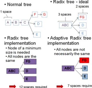
(4) Vol.2017-OS-140 No.8 2017/5/16. IPSJ SIG Technical Report. previous section. This section presents several considerations for this tracer implementation. 4.1 Overall structure The tracer is compososed by the lodding component embedded in the ECU software. The logging component has APIs that are called by AUTOSAR and the BSW when they are to log events to the designated storage. The APIs are called either explicitly from some software in the BSW or automatically from hook functions of AUTOSAR OS (see section for detail) when task switches and ISRs are invoked. When the log APIs are called, the logger in the tracer collects the information from the OS or the arguments of the called API, creates a log entry, and puts the entry into the log buffer. If a new log entry is to be written during the copy, the tracer simply discards the entry if there is a single buffer in the volatile memory, or puts the entry into another buffer if there are any. Upon the end of the copy, it unfreezes the buffer in the volatile memory, permitting later extraction of the data for analysis. 4.2 Events and APIs Based on the requirements, the minimum set of events to be logged by the tracer are tasks and ISRs. In the tracer, all the events are identified by their IDs, each of which corresponds to a single task, ISR, or a user-defined event. There is a single namespace of event IDs in the tracer. 4.3 Embedding the tracer To be able to log all the tasks and ISRs, the log APIs should be called when events are invoked. Embedding the calls to the functions by hand does not scale. Therefore, the calls should be made in the OS level. Note that the discussion here is only applicable to AUTOSAR tasks and Category 2 ISRs. Category 1 ISRs are excluded from the discussion because these ISRs are not managed by AUTOSAR OSes. AUTOSAR defines several hook functions in OS which are invoked when the corresponding events happen. The BSW developer can define a hook function, and configure the OS to call it. In the AUTOSAR standard only PreTaskHook and PostTaskHook are available. These functions are called when a task is about to start and stop, respectively. While the standard does not offer any way to hook invocation of ISRs, several AUTOSAR vendors provide propietary methods to achieve this, for example, by adding non-standard hook functions or providing callback facility independent of hook functions. We assumed that ISR-related trace APIs would be called by such vendor-specific facilities.. Table 1 Chronological log entry format Timestamp Event Identification (EID) Pre/Post bit. 2 byte format 8 bits 7 bits 1 bit. 4.5 Log Buffer There are one or multiple buffers in volatile memory in the logging component. Each buffer in volatile memory is used as a ring buffer to achieve FIFO. If there are multiple buffers, the buffers are used in a round-robin fashion. Each buffer also has a pointer to indicate the head of the ring buffer, which can be used as an indicator for logging new events. In order to attempt to minimize the maximum size of the log buffer while attempting to obtain the minimum amount of desired events, we include a compression algorithm that is described in detail in the following section. 4.6 Compression and the Adaptive Radix Tree (ART) When testing out the tracer implementation, we noticed that there were cyclical patterns in the data that we were obtaining. We believe that using a simple mapping between commonly seen patterns and a replacement character, we could slightly compress the information we were obtaining. Since the compression algorithm had to be implemented in an ECU and we couldn’t afford to take more memory away from the RTOS, we searched for a simple dictionary method to map between a defined set of events and a map. Noticing that there were patterns that could be said to depend on other patterns we look into the possibility of representing that information in a tree data structure that could hold a higher number of information in one node. This type of node was initially know as a PATRICIA tree. The original PATRICIA tree, now commonly referred to as a radix tree, was first described by Donald R. Morrison [11]. The structure is a space-optimized prefix tree in which only child nodes are merged with its parent. The data structure is extremely fast for data which can be expressed as strings, having found extensive use in text retrieval and network IP routing.. 4.4 Log size entry In our attempt to minimize the size of a log size entry, we decided on a 2-byte format are summarized in table 1. The information that should be contained in an entry is an Event Identification (EID) and a timestamp. In addition, a pre/post flag is required for task and ISR events, because the start and stop of the target task/ISR has to be distinguished. Fig. 1 Radix tree and ART space optimization. ⓒ 2017 Information Processing Society of Japan. 4.
(5) Vol.2017-OS-140 No.8 2017/5/16. IPSJ SIG Technical Report. The adaptive radix tree (ART) [12] is a variant of the radix tree that was proposed for databases that reside in main memory. A normal radix tree has one major drawback which is the constant node size. The ART softens this requirement, permitting nodes of multiple sizes. Figure 1 shows the space optimization for ARTs when compared to radix trees. This modification in the radix tree creation maintains the speed of a radix tree and improves its memory usage. Under performance tests, the ART outperforms red-black trees and GPT radix tree variants. The pattern information, which could create with EID start and stop records, we were seeing, were of variable lengths but could be grouped. Since this grouped pattern information would eventually need to be placed in ECU memory, the ART was a natural data structure choice. The common implementation of the ART involves the capability of the tree to be dynamically created in order to modify the tree node sizes as they become required. In ECUs, everything is statically allocated, so it becomes necessary to have a way to map the dynamically created ART to something that we could place statically into the ECU memory. We opted for a serialization method that maintained the ART definitions and permitted statically allocating the space required for the ART in the ECU. 4.7 ART Serialization Initially the start and stop records are organized into arrays. Each particular array is considered a pattern. In order to obtain faster pattern recognition, each pattern is assigned a corresponding value. Since we support Pre/Post and EID recognition, we are limited in supporting a limited number of patterns, as the corresponding value must fit into the 8 bits not being used by a Pre/Post EID. Once organized, the information is inserted into an ART that can be created dynamically, for example on a common computer. Once all the information is inserted into the ART, the serialization process is run. The serialization process simplifies the ART nodes by only serializing from the ART leaves to the root of the tree, obtaining an unsigned 8 bit array as a result. The resulting serialization format of ART leaves can be seen in Figure 2 and the resulting serialization format of ART nodes can be seen in Figure 3.. search on the task IDs in the children nodes area of the serialized ART node format seemed sufficient. 4.8 ART based compression Using the serialized ART, as soon as an event occurs, a sequential search that has historical memory is run against the ART. This means that for one event, only one check in the ART is realized. Once a set of events occur that can be mapped to a corresponding value, this corresponding value is then used to write the information to the main buffer. The idea behind replacing known patterns is that the data in the main trace buffer that has not been replaced becomes a point of interest when searching for possible faults. An added bonus of replacing the information in the main trace buffer is that a simple mapping compression is realized. The complete search and mapping can be seen in figure 4.. Fig. 4. Sequential pattern search. What is interesting about this sequential search, as is shown in figure 4 is that the method is capable of simple compression via character replacement. Due to sequential search inherently being a computation intensive task, we opt to not run the sequential search until after all critical ISRs are executed so as to not create possible issues with interrupt handling deadlines.. 5. Evaluation We evaluate the implementation of our tracer with the ART based compression and considering all the requirements explained in the previos sections.. Fig. 2 Serialized ART leaf. Fig. 3 Serialized ART node. The format becomes extremely important, because in the ECU, the anomaly detection has to be done on top of this format. Of extreme interest was the search for the next node after having searched through the whole node radix size. A simple binary ⓒ 2017 Information Processing Society of Japan. 5.1 Method for measurement We measured the overhead of our implementation using an onboard RH850 timer (OSTM). We also use this hardware timer to generate timestamps for the trace logs. The only issue with using this timer is that reading a timer value takes about 250 nanoseconds, and so cannot be used for measurement of a short amount of time. All our results are presented without the addition of the OSTM read time delay. Due to the tracer being implemented by the use of OS level hooks and callbacks, we measure the overhead of the Pre/Post Task and ISR hooks and callback for only the trace method and for the tracer method using the ART based compression algorithm. 5.
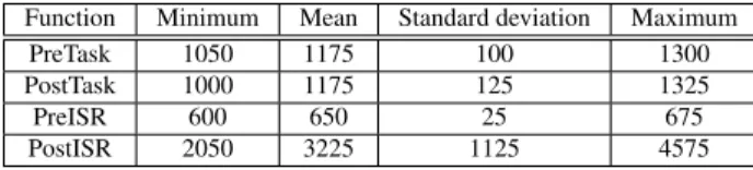
(6) Vol.2017-OS-140 No.8 2017/5/16. IPSJ SIG Technical Report. 5.2 RTOS load On our test RTOS, we only configured one 1 milliseconds OSTM timer interrupt, a 1 millisecond RTOS task and a 10 millisecond RTOS task. The tasks configured, did not have any dummy load. 5.3 ART patterns For the evaluation, we only used two simple patterns which derived directly from the RTOS load configuration from the previous section. The first pattern was, Pre OSTM timer interrupt, Post OSTM timer interrupt, Pre 1 millisecond task and Post 1 millisecond task. The second pattern was Pre OSTM timer interrupt, Post OSTM timer interrupt, Pre 1 millisecond task, Post 1 millisecond task, Pre 10 millisecond task and Post 10 millisecond task. The serialized ART from these patterns were placed into the RH850’s Code Flash for all tests.. 6. Results This section present the results of measure our implemented methods using the OSTM timer. Section 6.1 displays the results of running only the tracer, section 6.2 displays the results of running the tracer with the ART based compression method and section 6.3 shows the compression ratio obtained using the compression method. 6.1 Tracer The results for the execution of the tracer by itself are shown in table 2. What is very important to notice in our results is that the tracer obtained completely stable results for the configuration given. This makes it possible to use this sort of configuration in an automotive ECU, as long as the overhead is taken into consideration for more critical task or interrupt deadlines. Table 2 Overhead for the tracer for each hook in nanoseconds Function Minimum Mean Standard deviation Maximum PreTask 500 500 0 500 PostTask 500 500 0 500 PreISR 525 525 0 525 PostISR 525 525 0 525. 6.2 Tracer with ART based compression The results for the execution of the tracer with the ART based compression described in section 4.8 are shown in table 3 The results make it apparent that the introduction of the ART based compression has a big effect on the overhead. With the patterns that we decided to use, it is clear that the most calculation intensive hook is the PostISR, both because of the compression and because, as is noticeable in the PreISR results, the sequential search is not being executed for the PreISR hook. Although the overhead for the other hooks are stable, the amount of overhead could create inconveniences if there are extremely important ISR to be executed. However, even with the most CPU intensive hook, the overhead does not exceed 4600 nanoseconds. ⓒ 2017 Information Processing Society of Japan. Table 3 Overhead for the tracer with compression algorithm for each hook in nanoseconds Function Minimum Mean Standard deviation Maximum PreTask 1050 1175 100 1300 PostTask 1000 1175 125 1325 PreISR 600 650 25 675 PostISR 2050 3225 1125 4575. 6.3 Compression ratio We define compression ratio by the formula shown in equation (1). The results for the algorithm are shown in table 4.. Compression ratio. Uncompressed data size Compressed size. (1). We believe that the compression ratio we obtained using the ART based compression is adequate given the constraints given. This level of compression would permit more flexibility in designating buffer sizes for memory constrained devices. Table 4 Compression ratio obtained by using ART based compression Compression algorithm ART based compression. Compression ratio 1.27 : 1. 7. Conclusion In this research, we aimed to make it easier to debug faults and provide a solution performance issues by implementing tracing features on AUTOSAR OSes. We have provided the following results: • We have investigated the requirements for an OS tracer considering the microcontroller boards used by AUTOSAR OSes. • We have quantified 2 requirements. • We have implemented and evaluated the 2 requirements that we quantified. • We have established that the minimum overhead for the tracer on a ETAS RTA-OS using a RH850 microcontroller is around 500 nanoseconds. • Using a simple compression method based on an Adaptive Radix Tree, we can obtain a compression ratio of 1.27 : 1 while having the tracer and compression method only take around 4600 nanoseconds. • Using the compression method, we are able more flexibly set the trace buffers to maintain a desired amount of data. References [1] [2] [3] [4]. [5] [6]. Stacy C. Davis, Susan E. Williams and Robert G. Boundy, Transportation Energy Data Book; Edition 35, Office of Energy Efficiency and Renewable Energy, U.S Department of Energy, 2016 Daniel Sperling and Deborah Gordon, Two Billion Cars: Driving Toward Sustainability, Oxford University Press, 2010 Christof Ebert and Capers Jones, Embedded Software: Facts, Figures and Future, IEEE Computer Society Press, 2009 AUTOSAR Partnership, AUTOSAR Basic Information, Short Version, 2014, http://www.autosar.org/fileadmin/files/basic_ information/AUTOSARBasicInformationShortVersion_ EN.pdf Accessed: 2017-02-15 Technical Committee ISO/TC 22, Road vehicles, Subcommitte SC 3, Electronic, ISO 26262-1 Road vehicles - Functional Safety -, International Organization for Standardization, 2011 Charles M. Kozierok, Colt Correa, Robert B. Boatright and Jeffrey. 6.
(7) IPSJ SIG Technical Report. [7]. [8] [9] [10]. [11] [12]. Vol.2017-OS-140 No.8 2017/5/16. Quesnelle, Automotive Ethernet: The Definitive Guide, Intrepid Control Systems, USA, 2014 Daehyun Kum, Gwang-Min Park, Seonghun Lee, and Wooyoung Jung, AUTOSAR migration from existing automotive software. In International Conference on Control, Automation and Systems, 2008, ICCAS 2008, pages 558–562, Oct 2008. David A. Huffman, A Method for the Construction of Minimum Redundancy Codes, Proceedings of the IRE IEEE, USA, 1952 ETAS Group, ETAS RTA-OS, https://www.etas.com/en/products/rta_os.php Accessed: 2017-02-18 Renesas Electronics Corporation, RH850 Family (Automotive only), https://www.renesas.com/en-us/products/ microcontrollers-microprocessors/rh850.html Accessed: 2017-02-16 Donald R. Morrison, PATRICIA - Practical Algorithm to Retrieve Information Coded in Alphanumeric, Journal of the ACM, Volume 15 Issue 4, pages 514-534, 1968 Viktor Leis, Alfons Kemper and Thomas Neumann, The Adaptive Radix Tree: ARTful Indexing for Main-Memory Databases, In ICDE, pages 38-49, 2013. ⓒ 2017 Information Processing Society of Japan. 7.
(8)
図

関連したドキュメント
In the present paper, the criterial images for GIF- compression attack are selected by the proposed criterial image preparation method, and the obtained criterial images are added
In the present study, we describe a CCD video-probe equipped with a contact-type objective lens and illuminator, and evaluated it as a compact capillaroscopy for
The followings were obtained : the compression has three characteristic stages , in the first and third of which linear approximations are valid, and in the second of which
We present the optimal grouping method as a model reduction approach for a priori compression in the form of a method for calculating an appropriate reconstruction layer profile for
As the input files of different types arrive in an online fashion, we need to choose between the available compression methods, incurring the processing costs for each input, as well
We then introduce the notion of compression of a graph Γ which plays an important role in the study of partially commutative groups and prove that the lattices of closed sets for
Based on the Perron complement P(A=A[ ]) and generalized Perron comple- ment P t (A=A[ ]) of a nonnegative irreducible matrix A, we derive a simple and practical method that
First main point: A general solution obeying the 4 requirements above can be given for lattices in simple algebraic groups and general domains B t , using a method based on
